
Since several types of flotation circuits can generally be employed in conjunction with the various processes for the flotation of different classes of minerals, an outline of the standard circuits in common use is best given before the processes to which they are applicable are described. The flow sheets illustrating them are diagrammatic, but, in cases where the circuit includes two or more machines, the latter are shown in their approximate relative positions. The diagrams must not, however, be considered to represent exact plant layouts; any standardised arrangement will usually need a certain amount of alteration in minor details to suit a particular ore, not only to meet the requirements of the flotation process but also to conform to the design of the plant as a whole.
Flotation Circuits for Mechanically Agitated Cells
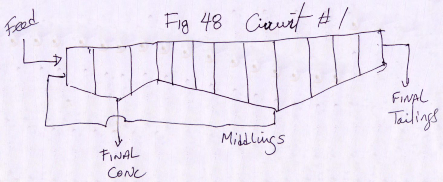
The simplest method of single-stage flotation with a machine of the mechanically agitated type is shown diagrammatically in Fig. 48. A finished concentrate
is taken off the first few cells and the remainder are run as scavengers, the froth from them being returned to the head of the machine through a middling pipe, as described in the previous chapter in connection with M.S. Sub-aeration and Denver “ Sub-A” Machines. This method can be operated successfully when the gangue is relatively unfloatable, but it requires rather more careful control than when a separate cleaning circuit is used.
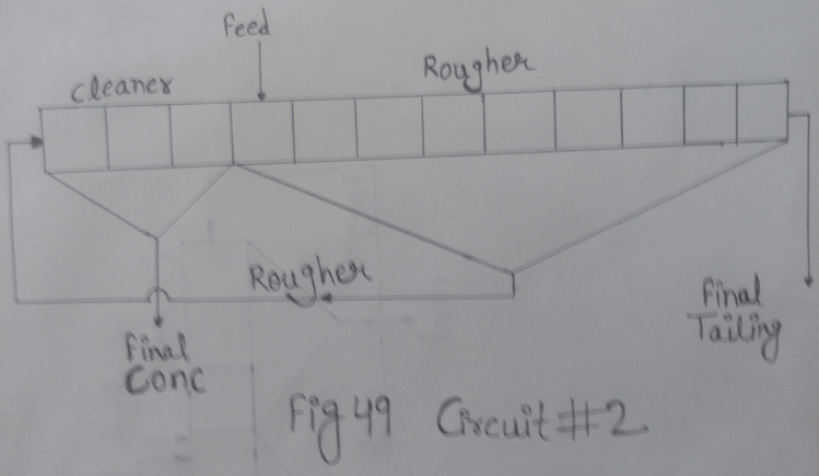
Circuit No. 2 (Fig. 49) is, as a rule, preferable to the preceding one, and it is advisable to employ it when a very clean concentrate is desired. The froth from the primary or roughing cells, termed the rougher concentrate, is diluted to a W/S ratio between 6/1 and 10/1 and transferred through a middling pipe to the cleaning section. This consists of a series of similar cells, varying in number from one-half of those in the roughing section for the treatment of a bulky low-grade rougher concentrate to one-quarter of the number when it is required to raise a small quantity of comparatively rich primary concentrate to the highest possible grade. It is usual, though not necessary, for the cleaning cells to be placed at the head of the machine. The tailing from the last cell is then mixed, as it overflows the discharge weir, with the incoming primary feed, so that both enter the roughing section through the transfer passage or pipe.
Circuit No. 2 is easier to regulate than No. 1 because the final concentrate is made in a pulp containing a much larger proportion of mineral than of gangue ; there is therefore less likelihood of gangue entering the froth and lowering the grade of the final concentrate. Moreover, variations in the character and rate of the feed, such as are encountered periodically, especially in small plants, may cause considerable alteration in the grade of the rougher concentrate before the change is noticed and the machine readjusted. Variations of this sort are evened out to a large extent in cleaning cells, so that the grade of the finished concentrate is affected very much less than would be the case if circuit No. 1 were in use.
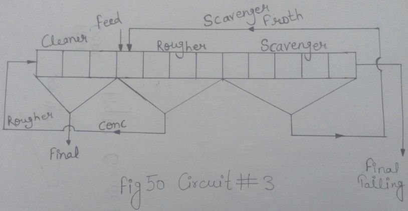
Circuit No. 3 (Fig. 50) is developed from the preceding one. Here the primary cells are divided into roughing and scavenging sections. The concentrate from the first section is re-treated in cleaning cells as before, but that from the latter part of the machine is returned to the first roughing cell through a middling pipe. Thus the cleaning cells receive a comparatively high-grade feed, whilst the scavenging section can be run with an excess of air so as to obtain the maximum recovery of the valuable minerals ; the resulting low-grade froth, being usually little richer in mineral than the normal run of ore, is best returned to the circuit with the primary feed. This circuit, besides being useful for ores that need the maximum amount of aeration at the end of the machine to give a profitable recovery of the valuable minerals, is often employed when the gangue is floatable and difficult to separate from the mineral. In the latter case, if one cleaning operation does not yield a concentrate of high enough grade, a re-cleaning section becomes necessary, such as is shown in circuit No. 4 (Fig. 51), in which the cleaner concentrate is diluted and re-treated in a separate series of cells. In this circuit the use of middling return pipes eliminates the necessity for pumping three separate concentrate products.
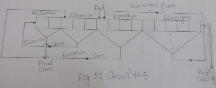
It should be noted that the diluting water of the cleaning cells in circuits 2 and 3 passes to the roughing cells and dilutes the primary feed, which ought therefore to contain a correspondingly smaller proportion of water as it leaves the grinding section in order that the dilution of the cleaner tailing may bring it to the correct pulp ratio in the roughing machine. Little further dilution of the primary pulp is involved when recleaning is practised, since the water added passes with the recleaner tailing to the cleaning cells where it constitutes the bulk of the diluting water, very little extra being normally required. Thus practically the same amount of water enters the roughing section in the cleaner tailing whether recleaning is practised or not. This also applies to the cleaning operations in the air-lift and pneumatic machines.
Flotation Circuits for Air-Lift and Pneumatic Cells
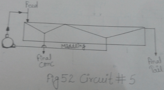
An air-lift machine can often be run as a rougher-cleaner cell, as in circuit No. 5 (Fig. 52), by taking a finished concentrate off the first few feet and returning the froth from the rest of the machine to the feed end. This method is also applicable to pneumatic cells, but its use is not common. As with mechanically agitated machines, careful control is needed if the required grade of concentrate is to be consistently maintained, and it is more usual, and generally more satisfactory, to employ a circuit such as No. 6 or 7, in which a separate stage of cleaning is included. Here the primary (rougher) concentrate is diluted as before to a W/S ratio between 6/1 and 10/1 before being sent to the cleaning section, and the cleaner tailing is returned to the head of the primary machine.
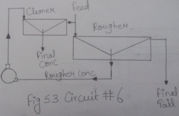
Circuit No. 6 (Fig. 53) is suitable when the feed flows by gravity to the rougher ; it is generally advisable to adopt it also in cases where the cleaning operation requires the addition of extra reagents, since the pump provides a convenient method of mixing them thoroughly with the pulp, but when it is necessary for the feed to be pumped to the rougher, circuit No. 7 (Fig. 54) has
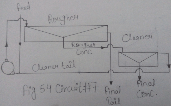
the advantage that the cleaner tailing can be elevated in the same pump, the primary concentrate flowing by gravity to the cleaning section. When vigorous aeration is needed to obtain a maximum recovery of
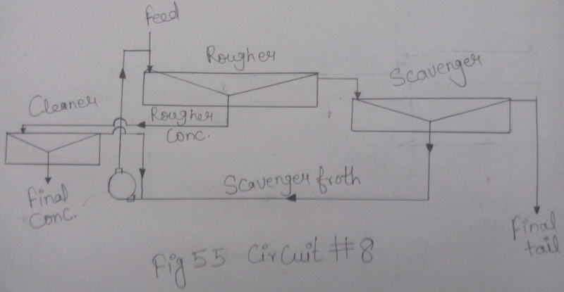
the valuable minerals, it is preferable to use separate roughing and scavenging machines, the scavenger froth being returned with the cleaner tailing to the head of the rougher. Of the two usual arrangements, circuit No. 8 (Fig. 55) is the simpler, requiring only one pump to handle both products, but, should the layout of the plant make it advisable to place the cleaning section above the rougher, circuit No. 9 (Fig. 56) with two pumps will be necessary. The second method has the advantage that the pumps provide points of agitation ahead of both the roughing and the cleaning sections for the addition of reagents, should they be required. It is usually possible to place the two pumps close together with a third between them so connected that it can be used as a spare for either of the other two. By separating the roughing and scavenging machines in this way a rougher concentrate without an undue proportion of gangue can be sent to the cleaning section.
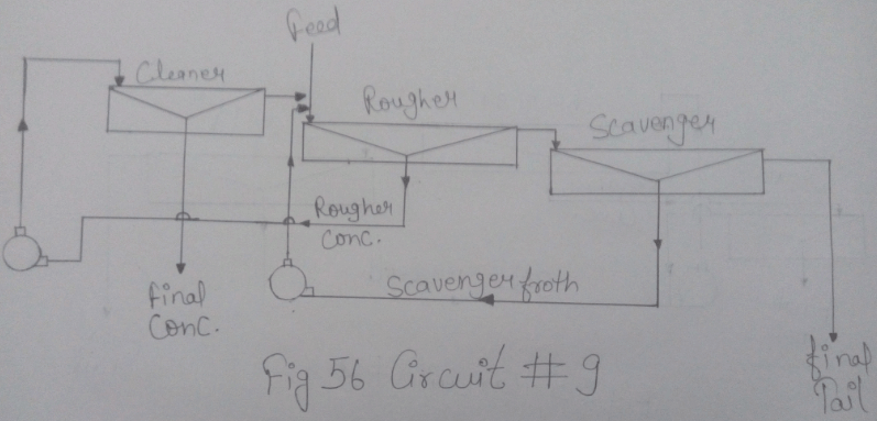
It will then be correspondingly easy to produce a final concentrate of the highest possible grade, while still maintaining maximum aeration in the scavenging section, the froth from which is returned to the point where the comparatively large amount of gangue in it does the least harm.
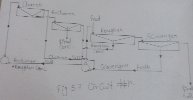
Even with separate roughing and scavenging sections it is sometimes found impossible to make a concentrate of high enough grade in the cleaner without allowing too much mineral to return in the tailing to the rougher, with consequent overloading of the latter section. In such a case recleaning is necessary, the cleaner concentrate being diluted with water and re-treated in a separate machine. Circuits 10 and 11 (Fig. 57 and 58) are the two most usual arrangements, but various modifications of the layout are possible to suit special cases. In fact, although the flotation method to be adopted is the primary consideration, the actual positions of the flotation machines in relation to each other and to the pumps handling the products must necessarily depend to a great extent on the requirements of the rest of the plant.
As in the case of mechanically agitated machines, a recleaning circuit involves very little more dilution of the pulp in the rougher than does one cleaning operation, since the diluting water in the second stage passes to the first stage with the recleaner tailing and serves the same purpose there.
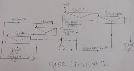
It occasionally happens that, although two cleaning operations are necessary to obtain a final concentrate of the required grade, the tailing from neither stage contains much mineral. In snch cases the circuit can be simplified by dispensing with one pump and sending the tailings from both stages to the head of the rougher, as is shown by the dotted line in circuit No. 11 (Fig. 58). The method has the disadvantage, however, that the diluting water from both cleaning sections enters the roughing machine and may make the pulp too thin. It is therefore preferable to pump one or both tailings to the classifiers in the grinding section, especially if they contain imperfectly ground material. Not only is the mineral then given another chance of entering the ball mill and becoming liberated from the gangue, but the water of the two tailings serves to dilute the pulp in the classifiers and does not then interfere with the density of the pulp in the roughing machine. The tailing from a single- stage cleaning operation is often returned in the same way to the grinding circuit, if it contains mineral which has not been completely liberated from the gangue.
Flotation Section Arrangement
When a large tonnage is to be handled, the flotation section of the plant is divided up into a number of parallel units, each consisting of one or more lines of roughing and scavenging machines with the appropriate cleaners. Occasionally, if the reagent mixture and control is simple, the grinding section is also designed in separate units, from each of which the pulp is discharged directly to the corresponding flotation unit. It is more usual, however, to send the discharge of the grinding section to a central distributor which splits the pulp up evenly amongst the flotation units ; the number of the latter need not then correspond to the number of grinding units.