
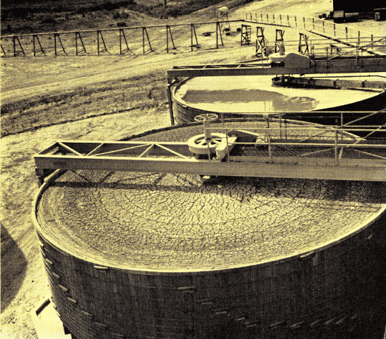
Aerial view of Susquehanna-Western, Inc., Uranium Mill near Falls City, Texas. Ore stock piles are upper center. The tailings line is seen at the upper right portion of the photo. Note the flat root and open wall design of the mill building.
The completion of this 300-ton per day mill marked the first commercial plant in Texas to treat uranium ores. The plant is owned by Susquehanna-Western, Inc., a totally-owned subsidiary of Susquehanna Corporation, Chicago, Illinois. In addition to this mill, Susquehanna- Western, Inc., owns and operates a 550-ton per day uranium mill and a 250-ton per day sulphuric acid plant at Riverton, Wyoming. The 400-ton per day uranium mill of Mines Development, Inc., at Edgemont, South Dakota is also owned by the Susquehanna Corporation.
Susquehanna-Western, Inc., and Mines Development, Inc., are under the capable direction of Mr. Allen D. Gray, President of both firms. The companies are also engaged in exploration and production of minerals other than uranium.
Initial discussions with the Atomic Energy Commission for a yellow cake purchase contract in Texas commenced on November 23, 1959. The contract resolved provides for the purchase of a maximum of 1.6 million pounds of U3O8 for the period ending December 31, 1966 at a price of approximately $9.90 per pound prior to March 31, 1962, and $8.00 per pound thereafter. The total value of the contract is $13,000,000.
The majority of uranium processing plants constructed in recent years were allowed an accelerated amortization schedule up to 1962. However, this mill was built at a time that did not permit the full realization of the previous favorable amortization schedule. The company therefore established a policy to achieve maximum metallurgical efficiency and profit but not one dime could be spent unless necessary to attain this goal.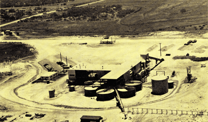
Location
This mill is located in Karnes County, approximately 50 miles southeast of San Antonio, Texas, or about 10 miles southwest of Falls City.
Most employees were hired locally from the nearby towns of Falls City, Poth, Karnes City, and Kennedy. The site was selected due to its proximity to the mining area and the availability of power, water, natural gas and living facilities. The mill operates twenty-four hours per day, five days per week and employs approximately sixty persons.
Design and Construction
Design and construction of this nearly $2 million facility was accomplished in eight months by Susquehanna Engineering Company, a division of Susquehanna-Western, Inc. Process and metallurgical design were by H. L. Hazen, Inc., Metallurgical Consultants to Susquehanna. O. W. Walvoord, Inc., of, cooperated as construction consultant and design manager. More than one hundred construction people were employed during the peak period.
Mr. G. H. Bryant, Manager of the Metallurgical Division for Susquehanna-Western, Inc., coordinated all phases of the project. Mr. George Wallbank was Project Engineer for Susquehanna Engineering.
The mill operating staff consists of Ron Bethurum, Mill Superintendent; Gene Cooley, Control Engineer; Waynard Jensen, Production Foreman; Carl Bennett, Maintenance Foreman; and L. A. McGill, Office Manager.
Mining
The source of ore for this plant is from the company operated Luckett open pit mine some two miles away and a 100,000-ton stockpile of ore owned by the AEC. Independent shippers will ship ore to the plant in the future.
Prior to the start of mining the first ore body, it was necessary for Susquehanna-Western, Inc., to drill 15,000 feet of exploratory holes to delineate the mining area. After this was completed, the DRD Construction Company of San Antonio removed over 300,000 tons of earth to reach the ore. Actual mining commenced on November 10, 1960, and is now progressing at an average rate of 14,000 tons per month. The deposit covers 17 acres and varies from 4 to 12 feet in thickness. The ores contain an average of 20% moisture and are loosely cemented sandstones with a relatively high content of bentonitic-type clays. Control drilling of the ore body continues as a guide to mining. Each sample is carefully prepared and placed in a scaler which, in a space of minutes, totals the gamma radiation and particle emissions to give the uranium content of the sample.
A full time exploration crew is engaged in the area investigating other possible ore deposits for mining at a later date.
The ore is hauled to the plant site in trucks, weighed and deposited in 300-ton stockpiles around the ore receiving hopper. Moisture samples are taken from each lot of ore to determine the dry weights.
The ores have an average U3O8 content of 0.22%.
Crushing and Sampling
Since the ores contain as much as 20% moisture and are characterized by varying amounts of bentonitic- type minerals that deter thickening rates, drying and calcining at 600° to 800° F. is necessary prior to processing.
The ores are fed directly from the stockpiles by means of a rubber tired loader to the ore receiving hopper. The hopper is fed around the clock by one front end loader operator per shift. The hopper is discharged using a revolving roll-type grizzly feeder. The oversize is crushed to 1½” in a traveling grate-type swing hammer mill because of the sticky nature of the feed. When the crusher is out of service for any reason, the feeder can be reversed and ore from a crushed ore pile delivered to the plant.
The inclined 18″ x 223′ belt conveyor that receives the crushed ore and delivers it to the surge bin is equipped with a plow at a point about half way up the conveyor. This plow can be positioned so that the crushed ore can be scraped off the belt into a chute that delivers directly to a truck below. The truck piles the ore on a crushed ore stockpile to furnish the mill requirements when the crusher is out of service.
The 25-ton surge bin in the main plant flow is equipped with a level control device that automatically stops the initial crude ore feeder. At this point the front end loader operator has about an hour’s free time for other work or until a signal notifies him to start crushing again.
No large fine ore storage bins are used because of the sticky nature of the ores. Ore is drawn from the 25-ton surge bin by a 36″ wide belt conveyor that travels under the full length of the bin. This bin and feeder are specially designed to handle this difficult ore.
As the ore falls from the feeder belt, it is cut by a Automatic Sampler equipped with a Type “C” Dry Cutter. The inside bottom of the cutter has a 60° slope and is lined with Teflon to prevent any ore fines from sticking to the cutter. Teflon is a plastic made from fluorine and has practically no coefficient of friction. A cut is made every 10 minutes and amounts to about one pound of sample per ton of ore. This sample represents the mill feed and is dried, crushed to ¼”, split through a Jones Riffle, mixed, crushed to 10 mesh, and ground preparatory to analysis for U3O8.
Calcining and Grinding
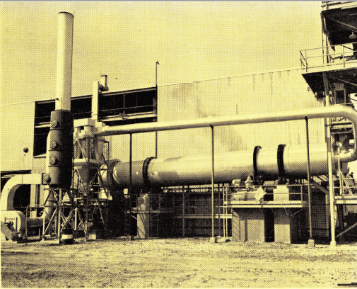
The ore from the 25-ton surge bin falls through a chute into the 6′ x 50′ Standard Steel Countercurrent Kiln. This chute is lined with Teflon at critical points.
The refractory lined kiln is normally operated at 800° F. The burner is rated at a maximum of 18,000 cubic feet of natural gas per hour. This will deliver 18,000,000 BTU’s per hour which is sufficient to calcine 300 tons per day of the bentonitic-type ores containing 21% moisture. A standby gasoline engine is provided for kiln rotation in the event of power failure. This precaution is necessary to prevent severe warpage of the shell.
The hot dust-laden gases from the kiln pass through cyclones to remove most of the dust and then through a wet strubbing tower. The dry dust from the cyclones are fed to the same vibrating feeder that delivers the hot calcine from the kiln to the quench unit. The slurry from the scrubbing tower is pumped to the same quench unit. Provision is also made to bypass the kiln for certain ores that do not require calcining.
The quench unit consists of a 36″ x 19′-10″ Spiral Classifier tilted so that all the pulp is discharged from the sand end of the classifier. This classifier, which has a full-flared tank, is of modified design for handling pulp at near boiling temperature.
The discharge from the quench unit feeds directly to a 3′ x 8′ Steel Head Rod Mill operating at 32 RPM, and equipped with a 30-HP high starting torque motor. This is a small rod mill for a 300-ton per day plant but was selected due to the softness of the ore and the need of reducing the ore to only grain size. The feed scoop was specially designed for this installation as the standard feed scoop for a rod mill of this size would not handle the high feed rate required. The trunnion bearings of the rod mill are water cooled due to the high temperature of the pulp. A 24″ x 12″ Trommel Screen is attached to the large diameter discharge trunnion and fitted with a ¼” screen cloth to remove any oversize or tramp material ahead of the leach system.
Leaching
The pulp from the rod mill (approximately —20 mesh) is pumped at 45% solids to four 13′ x 13′ Heavy Duty Turbine Agitators. Sulphuric acid is added in the first agitator to produce a pH of 1.0 for dissolution of the uranium. The average leaching temperature is 140° F. which is due entirely to residual heat of the hot pulp from the calcining and grinding circuit. The use of an oxidant is not required for extraction. Extraction is in excess of 95% of the contained U3O8.
The agitators are equipped with 42″ diameter Turbine – Type Propellers driven by 15-HP motors. The shafts and propellers are rubber covered. All leach tanks are 4″ nominal thickness wood stave tanks with polyethylene covered bands for protection from the acid pulp.
Calcining of the ores at 800°F. prior to processing is required to dehydrate the bentonitic clays and thus improve the settling characteristics of the ore.
Classification and Thickening
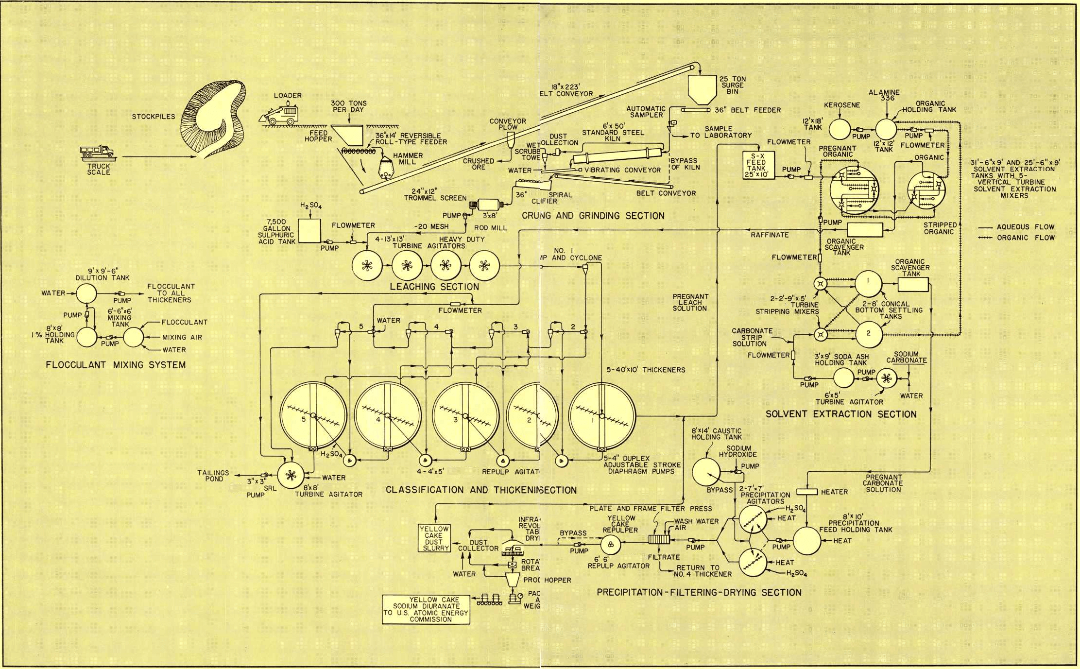
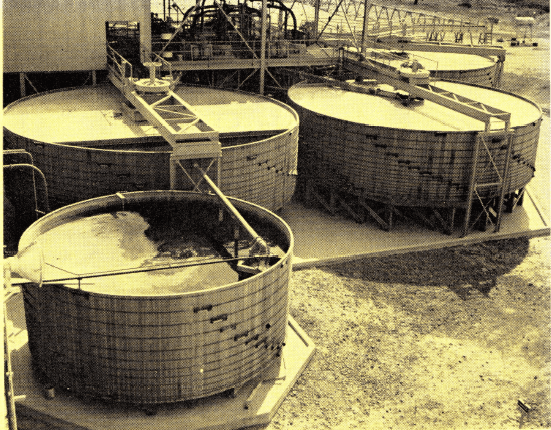
The leach pulp is pumped to a series of five 10″ cyclones and five 40′ x 10′ acid proof thickeners. The sand fraction from the cyclone underflows are counter-currently washed in each successive cyclone stage. The cyclone overflows are countercurrently washed in the thickeners. Fresh water and raffinate (spent leach solution) from the solvent extraction system are added to the last cyclone. This combined classification and thickening washing circuit is illustrated on the flowsheet.
The sand underflow from the No. 5 cyclone and the thickened slime underflow from the No. 5 Thickener are combined in an 8′ x 8′ Turbine Agitator and then pumped to the tailings pond about 1000 feet away using a 3″ x 3″ SRL Sand Pump. The agitator is equipped with a 24″ diameter rubber covered Turbine-Type Propeller driven by a 7½-HP motor.
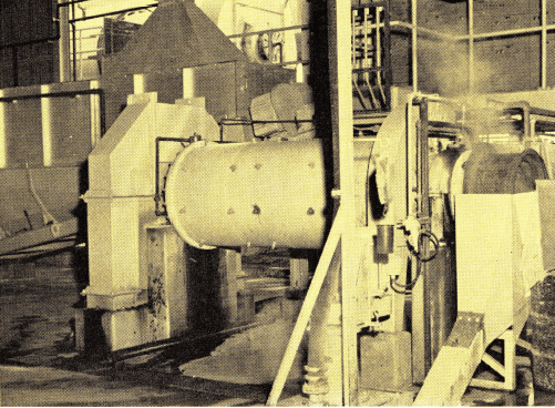
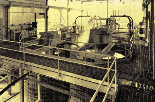
The 3′ x 8′ Rod Mill handles 300 tons per day of Susquehanna calcined uranium ore. A special scoop feeder was developed to handle this exceptionally high tonnage for such a small rod mill. Feed to this unit is from a 36″ Spiral Classifier which serves as a quench tank for the hot calcine.
Acid leaching of the —20 mesh ore takes place in four 13′ x 13′ Heavy Duty Turbine Agitators equipped
with 42″ diameter propellers and 15 HP motors.
The acid proof Thickeners have rubber covered wetted parts with the exception of the rake blades and feed well which are Type 316 stainless steel. The wood stave tanks are 4″ nominal thickness.
Each of the five thickeners is equipped with a 4″ Duplex Adjustable Stroke Diaphragm Pump for removal of the thickener underflow at about 40% solids. These pumps have rubber covered bowls and valve seats; all other wetted parts are constructed of Type 316 stainless steel.
The underflow from each thickener is repulped in separate 4′ x 5′ Heavy Duty Open Type Agitators using 15″ diameter rubber covered Turbine-Type Propellers driven by 2-HP motors. This repulping step breaks up all slime flocs and prevents entrainment of solution for the purpose of achieving a high washing efficiency.
Separan is added to each thickener for flocculation of the slime. Other flocculants are also being evaluated.
Solvent Extraction Recovery System
The solvent extraction process, as applied to uranium treatment, is a liquid-liquid method of ion exchange in which the uranium content of the acidic aqueous solution is selectively transferred to an immiscible organic chemical solvent. The uranium depleted aqueous solution is termed raffinate and is phase separated
The Heavy Duty Turbine Agitators are of acid-proof construction. Shafts and propellers are rubber covered. Wood tanks have polyethylene covered bands.
from the uranium-bearing organic due to the immiscibility of the two liquids. Following this extraction and phase separation step, which usually consists of four or five stages, the uranium-bearing organic solution is stripped of its uranium content using a soda ash or acidified sodium chloride solution. This step is essentially the reverse of the extraction circuit. The organic is then reused and the enriched uranium strip solution is precipitated to produce the final high purity uranium yellow cake.
The overflow from the No. 1 Thickener, pregnant leach solution containing 0.6 grams U3O8 per liter, flows by gravity to a 25′ x 10′ holding tank which is the feed for the solvent extraction system. Feed to the solvent extraction circuit is pumped through a control flowmeter at the rate of 150 GPM.
The solvent extraction system is of the latest design. It consists of two wood compartmented extraction tanks, one 31 ‘-6″ diameter x 9′ deep with three mixer-settler units and the other 25′-6″ diameter x 9′ deep with two mixer-settler units which provide a total of five stages. This internal type extractor eliminates the need of expensive acid proof piping required for individual units. Pumps or airlifts are not required. Each mixing compartment is a special Vertical Pumping Turbine which advances 150 GPM of aqueous, 22 GPM of organic and also recirculates 150 GPM of the organic. It also provides contact between the aqueous and organic phases in the mixer compartment. Type 316 stainless steel is used for all wetted parts of the mixer.
The pregnant leach solution enters the No. 1 mixer and progresses through the five stages of extraction countercurrent to the flow of organic extraction which is added to the No. 5 mixer through a flowmeter. The raffinate flows to a rectangular-shaped scavenging tank where a small amount of organic is recovered and returned to the circuit. A portion of the raffinate is pumped to the No. 5 cyclone in the classification thickening section and used to supplement the addition of fresh repulping water at this point. The raffinate, or any part of it, can be added to the plant tailing and sent to waste if desired.
The organic solution used consists of 5% Alamine 336, 2.5% Isodecanol, and 92.5% kerosene. These proportions are on a volume basis.
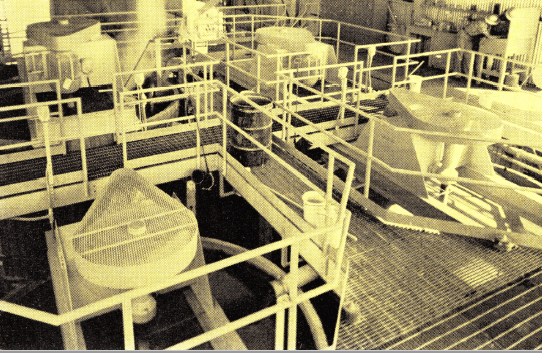
The pregnant organic from the No. 1 mixer of the extraction circuit contains approximately 6 grams of U3O8 per liter and is stripped in two stages. The stripping mixers consist of two 2′-9″ diameter x 5′ deep Vertical Turbine Mixers with Type 316 stainless steel vertical turbines driven by 1.5-HP motors. The settlers are 8’ diameter conical bottom tanks. The first stripping agitator is P.V.C. lined, both settlers and the second agitator is made of steel.
The stripping solution is 10% soda ash and is fed countercurrent to the pregnant organic through a flowmeter at the rate of 2.5 GPM. Acidified sodium chloride solution is commonly used as a stripping solution, but the more expensive soda ash solution was chosen in this case because the ore contains small quantities of molybdenum. Soda ash will strip both uranium and molybdenum from the organic, and, therefore, will not allow the molybdenum to build up in the amine organic after constant recirculation in the system. Acidified sodium chloride will recover the uranium but not the molybdenum from solution. Excessive molybdenum will interfere in the solvent extraction if not removed. The stripped organic is returned to the organic make-up tanks and fortified periodically as determined by
analysis.
The preparation and handling of the organic solution and the carbonate stripping solution is illustrated
on the flowsheet.
The pregnant carbonate solution flows through a rectangular-shaped organic scavenging tank before it
goes to precipitation to remove small quantities of
The five-stage solvent extraction system eliminates all need for acid-proof pumps and piping. The mixing and settling and counter-current flows of both the aqueous and organic phases take place in the Solvent Extraction System.
organic. The organic is periodically collected from the tank and reused in the organic system.
Precipitation and Drying
The pregnant soda ash solution after stripping contains about 40 grams of U3O8 per liter and is fed to an 8′ x 10′ holding tank where it is heated to 130° F. The holding tank is discharged by means of a pump and alternately feeds into two 7′ x 7′ Paddle-Type Batch Precipitation Agitators equipped with 3-HP motors. The paddles and shaft are rubber covered.
When ore containing little molybdenum is treated the carbonate pregnant solution is precipitated by first acidifying to a pH of 3.0 with sulphuric acid to destroy all carbonate compounds and to drive off the CO2. The temperature is 130° F. The uranium is then precipitated
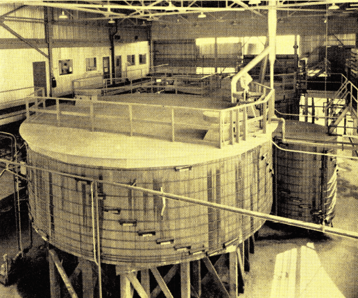
Thickener o’ flow from the 40′ x 10′ acid-proof Thickener (center) flows to the solvent extraction holding tank at lower left. Thickener underflow advances counter-currently through five stages of repulping and washing.
as a yellow sodium diuranate by adding caustic soda and raising the pH to 7.0. When ore containing too much molybdenum is milled, sodium diuranate is precipitated by adding 3 grams per liter excess caustic soda to the carbonate solution. This last precipitate is difficult to filter and wash but meets AEC molybdenum specifications.
The slurry containing the precipitated uranium is pumped to a plate and frame filter press for filtration and washing for the removal of soluble impurities. Special provision is made to catch rain water off the mill roof and to use potable water for the purpose of washing the filtered yellow cake. The well water used for milling is so impure that it will kill cattle if allowed to drink it. The well water cannot be used for washing the filter cake. Special care must be exercised at this
Acid-proof Thickeners have rubber-covered wetted parts. Rake blades and feed well are of Type 316 Stainless. Final thickener o’flow is sent to solvent extraction circuit. Final thickener underflow is sent to tailings pond.
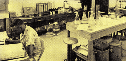
Modern laboratory equipment and techniques provide efficient mill control.
point to insure that the yellow cake will meet AEC specifications.
After the yellow cake is washed, it is discharged from the filter, repulped in a 6′ x 6′ Turbine- Type Agitator equipped with a 24″ diameter propeller, and pumped at 50% solids to the center of a 9′ diameter revolving table dryer. Gas-fired infrared heaters are placed about 12″ above the rotating table for evaporation of four pounds of water per square foot per hour. The dryer will evaporate about 90 pounds of water per hour and produce about 2,100 pounds of dry yellow cake per 24 hours. The rotating table is made of flat steel plate with a ¼” raised edge and is supplied with stationary rabbles for moving the yellow cake from the center feed point to the peripheral discharge edge. It is also provided with rollers which break up lumps of yellow cake to permit effective drying and to minimize lumps in the discharge. The unit is completely enclosed in a hood under suction. Windows are placed so that the operation can be observed at any time.
The dried yellow cake falls through a rotating breaker that works all the lumps through a ¼” screen and then to the product hopper for packing in 55-gallon steel drums for weighing and shipment.
Special attention was given to the dust collection facilities in the drying and packaging part of the plant. The dust is collected in a wet-type dust collector and this product is returned to the 25′ x 10′ solvent extraction holding tank where the yellow cake is readily dissolved and reprocessed in the extraction circuit.
Fire Protection and Water Supply
Water is pumped from an 840 foot deep well along side the mill to a 250,000 gallon tank at the rate of 300-GPM. The overflow from this tank supplies the mill water tank. The 250,000 gallon tank is therefore kept full at all times and is available for fire protection. Whenever a fire water valve is opened, a 150-HP diesel engine that drives a 1500-GPM fire pump automatically starts up. This fire water system is fully automatic. A small jockey pump and electric motor maintains pressure in the fire system, and the automatic fire pump starts up whenever the pressure falls below a preset pressure.
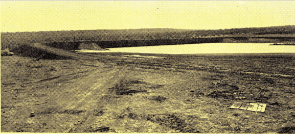
Tailings are pumped by a 3″ x 3″ SRL Pump to a large earthen dam about 1000 feet from the mill.
Electric Power and Natural Gas
The Central Power and Light Company erected a power line and installed a substation near the mill at no cost to Susquehanna-Western, Inc.
Natural gas was available approximately 4.3 miles from the mill. Susquehanna-Western installed a 2″ pipe line to furnish the mill requirements from the 200 pound pressure main gas line of the United Gas Pipeline Company.
Laboratory
In addition to the sample preparation laboratory, the company operates a plant control laboratory for analyzing solutions by the fluorimetric method. Ore and mill pulps are prepared at the mill but sent to another laboratory for volumetric analysis.
Office
The main office is a separate air conditioned building located near the mill. All clerical phases of the mill are performed in this office. The foreman and shift boss offices are located in the mill so that the entire operation can be seen from the office windows.
Conclusion
Flowmeters, pyrometers, and other technical instruments have been provided so the plant can be operated with maximum metallurgical efficiency. Attention has been paid to the comfort and well-being of all employees and the plant has been arranged for easy maintenance and operation. All major equipment is serviced by overhead cranes. The grinding, leaching, solvent extraction, and precipitation sections are covered with a roof but much of the mill is open on the sides. The thickeners are located in the open.