Table of Contents
- MINERAL JIG SIZING & DESIGN CAPACITY TABLE
- SIMPLEX JIG
- DUPLEX JIG
- WORKING PRINCIPLE FOR EFFECTIVE JIGGING
- TYPES OF JIGGING MACHINES
- JIG DRIVES
- HAND OF THE JIG
- JIG SIZES AND JIGGING CAPACITY
- HOW DOES A JIG WORK
- TYPES OF JIGS
- PRINCIPLES OF JIGGING
- IDEAL JIG STROKE
- THE BAUM JIG
- INSTALLATION OF THE BAUM JIG
- OPERATING SUGGESTIONS FOR THE BAUM JIG
- OTHER TYPES OF JIGS
- SUGGESTIONS ON INSTALLATION AND ADJUSTMENT
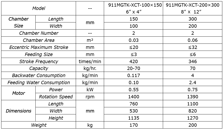
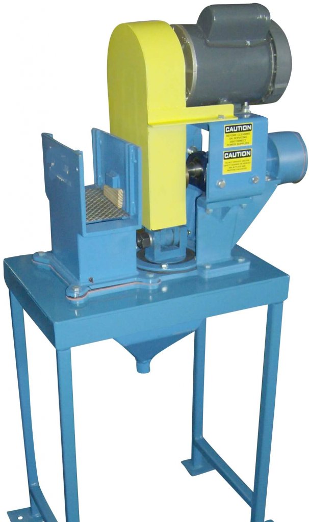
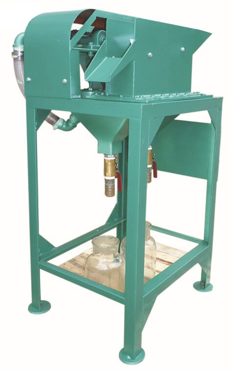
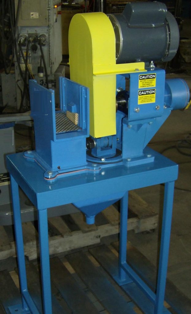
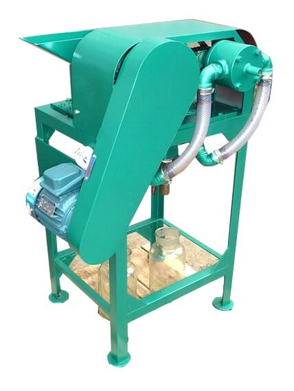
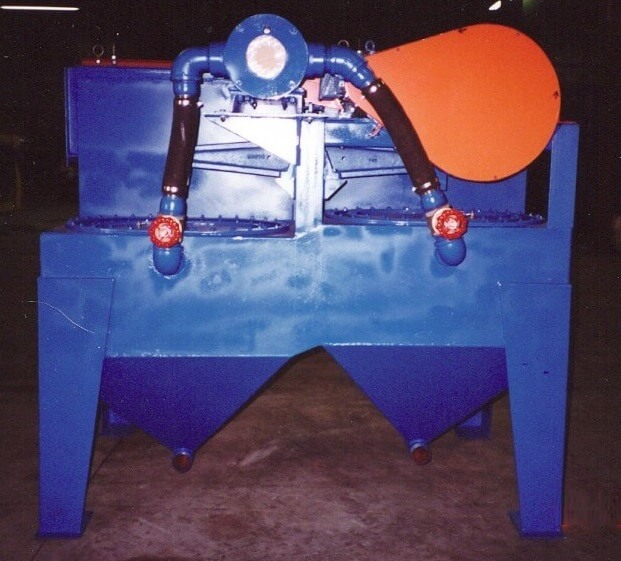
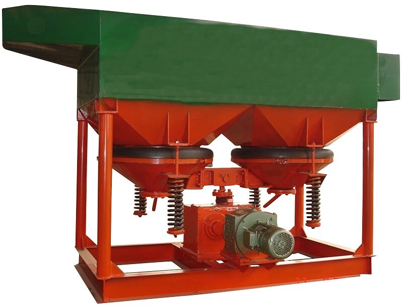
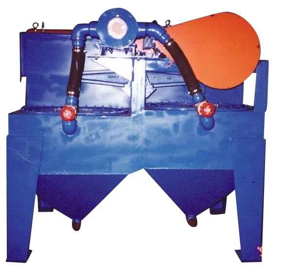
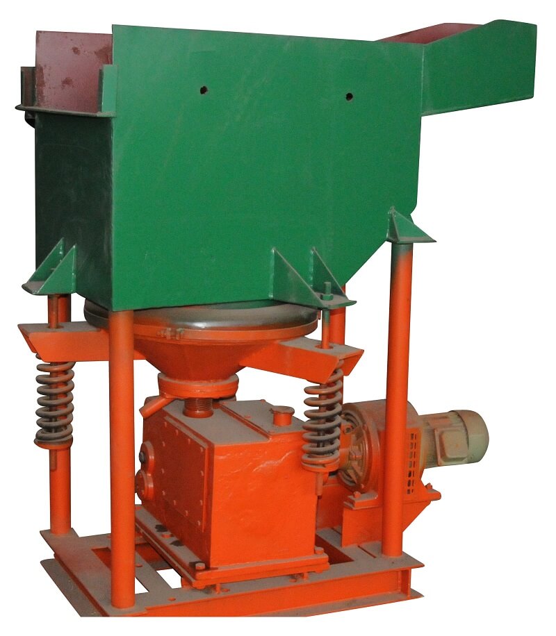
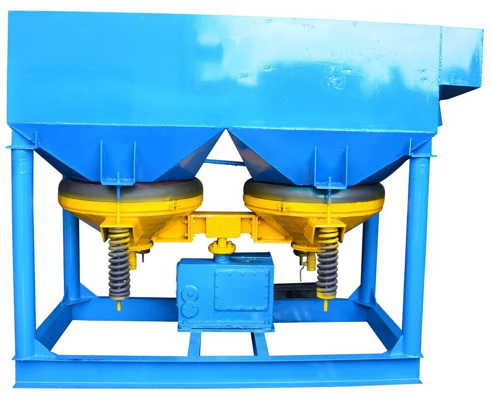
The Duplex Mineral Jig Machine belongs to gravity concentrating device that separates material based on differing densities of the material. The Jig is widely used in concentration of heavy minerals such as tin, gold, tungsten, manganese and barite. The 911MGTK-XCT Laboratory Mineral Jig Machine is an ideal instrument for research of beneficiation of ferrous metal and nonferrous metal.
Laboratories or small tonnage producers can select from either a 4″ x 6″ or a larger 12″ x 18″ and start jigging now!
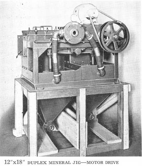
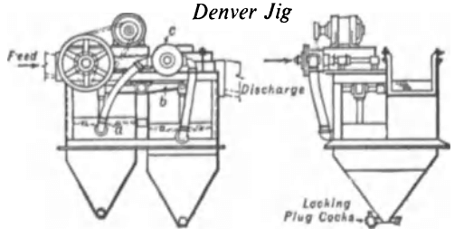
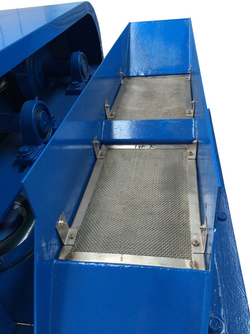
The Duplex jig was designed in the first place as a unit cell working in the closed circuit of a ball mill. It can take a long-ranged feed, and involves but little loss of height between mill discharge and delivery of its tailing discharge to the classifier. The rotary valve c can be adjusted so as to open during the required portion of the jigging cycle, thus admitting hydraulic water in phase either with the suction or the pulsion stroke, which is applied by means of a flexible diaphragm a. This modification in jig design has led to increasing applications of the machine, which can be adjusted so as to produce fairly sharp separation of material down to coarse sand sizes. Duplex jigs embodying this phased control of the hydraulic water are now used outside the closed circuit, one important application being in the “roughing” of diamond gravels. By suitable adjustment of the rotary water-valve any desired variation can be arranged, from complete neutralisation of the suction stroke with hydraulic water to a full balance between suction and pulsion. Jigging is through a wedge-wire screen.
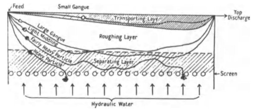
Under working conditions the contents of the ore box sort themselves into three fairly distinct layers. At the bottom is the separating layer, which should be maintained at a grain size and density suited to the severity with which it is to oppose penetration by particles from the feed. In jigging through the screen the concentrate must fall through this bed, which may be autogenous, but is usually composed of particles of a material chosen for its specific gravity, of a size larger than the screen openings.
 |
 |
 |
 |
 |
 |
 |
 |
 |
 |
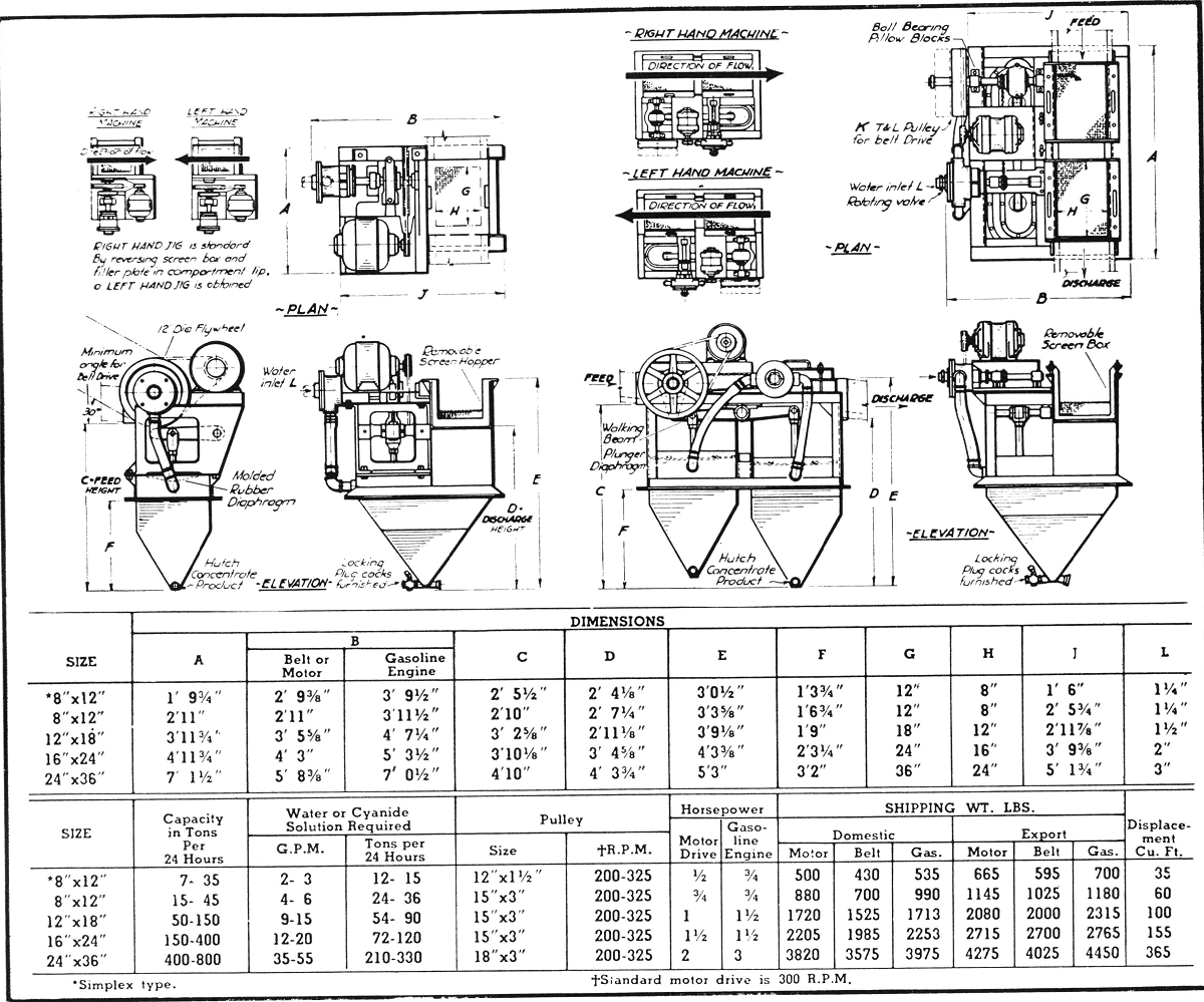
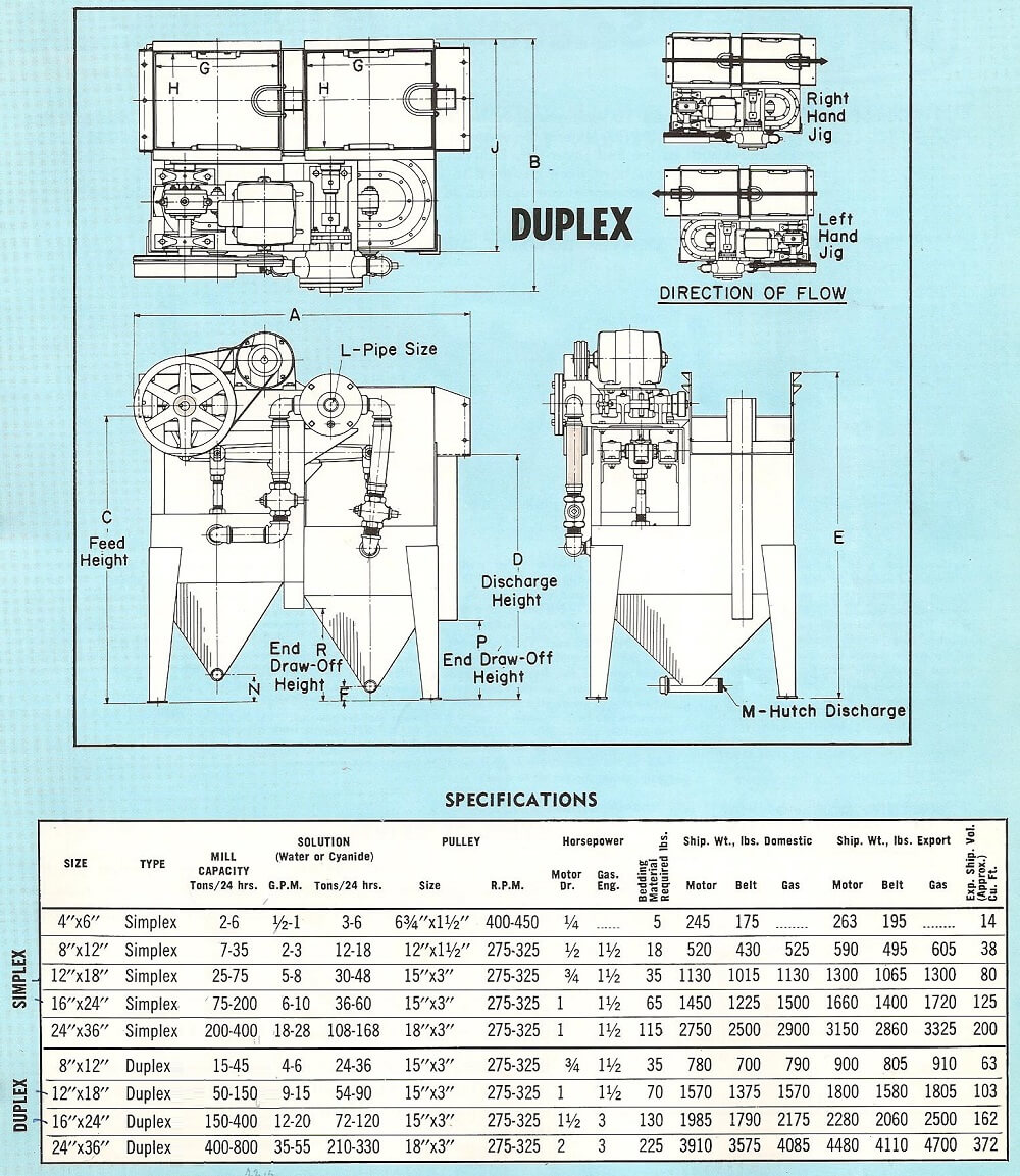
MINERAL JIG SIZING & DESIGN CAPACITY TABLE
SIMPLEX JIG
&
DUPLEX JIG
Contact me for any large duplex gold jigs listed on the table below.
The Mineral Jig is not just another gravity Separation Process. It is a highly efficient selective pulsator and concentrating machine which has the ability to treat an unclassified feed separating solids having only a slight differential in settling rates, with only a minimum addition of water.
1000s of these Mineral Jigging machines are now in operation on a “24-hour per day” basis and they are successfully used on practically every type of ore ranging from massive sulphide to others low in mineral ratio, and some which are completely oxidized. Both metallic and non-metallic ores are being handled, with equal efficiency.
The principle behind the success of the Mineral Jig focuses around its adaptability to a wide range of problems under varying operating conditions large capacity, minimum water requirements, extreme selectivity, foolproof jigging operation.
WORKING PRINCIPLE FOR EFFECTIVE JIGGING
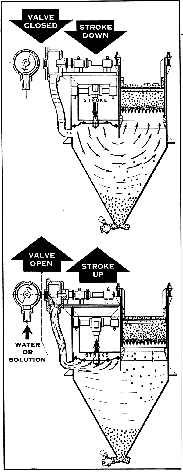
The Mineral Jig operates on the basic principle of hindered settling, and in order to effect a concentration it is necessary that there be a differential in the settling rate of the solids treated. As there is an accumulated differential in settling rates in the grinding mill discharge of a conventional closed grinding circuit, this is an ideal feed for the MINERAL JIG. In addition, this is an enriched product due to the settling and trapping of the higher specific gravity mineral particles in the classifier pool, and concentrate removal from the closed circuit is imperative.
The illustration at the left clearly shows why the MINERAL JIG is distinctive and differs radically from a conventional type jig and why it has been called a pulsating selector.
In the upper sectional view the rotating water valve (synchronized with the eccentric shaft) has closed and the plunger is moving the diaphragm on its downward stroke which creates an upward pulsation to the JIG bed. During this period lighter gangue particles are carried further than the heavier mineral particles which may even settle against the upward movement in the pulp. At the completion of the upward pulsation the rotating water valve has passed through a 180° arc or half of a circle.
TYPES OF JIGGING MACHINES
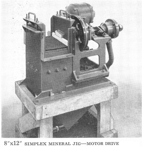
The Mineral Jig is built in two general types, simplex and duplex. The duplex type is built in all sizes while the simplex is standard in the 8″x 12″ size only.
The simplex unit consists of one screen compartment, one hutch, and one screen box, while the duplex is just double, i. e., two screen compartments, two hutches, and two screen boxes.
Each machine is furnished standard with sufficient shot for initial bedding, locking hutch cocks for each hutch, necessary screens and equipped for operation. To facilitate changing screen boxes it is recommended that a spare screen box with screens be available, although this is not necessary.
JIG DRIVES
ALL JIGS are available in any of three types of drives, i. e., belt, motor and gasoline.
MOTOR DRIVE: Motor driven units may be of any standard electrical characteristics, either A.C. or D.C. Splash proof motors are recommended and furnished as standard. The drive is through V-belt to the grooved Jig flywheel. Electrical characteristics of the Jig power supply should always be given.
BELT DRIVE: All units may be belt driven from lineshaft to Jig flywheel. Except in the case of the simplex unit, a loose pulley can be furnished if desired. The Jig flywheel acts as the tight pulley.
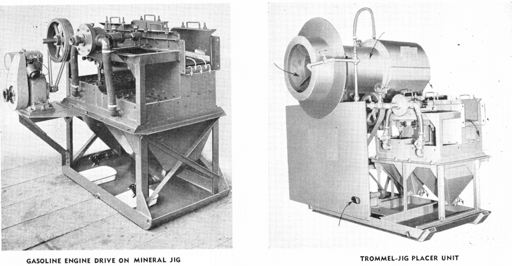
GASOLINE DRIVE: Gasoline Engines are used to power all sizes of Jigs through V- belt to grooved flywheel. For isolated localities this makes an ideal unit. All Mineral Jigs are readily adaptable to airplane transportation due to compact nature of the various units.
HAND OF THE JIG
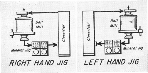
The Hand Of The Simplex Jig is interchangeable, left or right, and may be adapted to any grinding circuit.
The hand of duplex Jigs is determined by facing the rotating water valve, and with feed entering from the left and passing to the right, the Jig is right hand. A Jig is a left hand unit when facing the rotating water valve—mechanism side; the feed passes from right to left. Note the layout drawings showing the hand of Mineral Jigs. In any conventional grinding mill-classifier circuit the Mineral Jig can be installed in place of the regular launder as the flow slope over the Jig is the same as with the launder.
JIG SIZES AND JIGGING CAPACITY
HOW DOES A JIG WORK
It is often hard for people to understand exactly how jigs work. For what it’s worth, I will put forth my understanding of the principles.
Simply stated a jig is a device which has a couple of basic advantages over a sluice box.
- It is continuous and only needs occasional clean up (its biggest drawing card to hard rock mills).
- It maintains, if properly balanced, an intermittent fluidized bed capable of retaining finer gold than a sluice box.
- If not properly balanced it can be more disastrous than a sluice box.
A properly functioning jig is dependent upon a number of factors; feed flow density, feed flow rate, pulse rate, hutch water input, hutch concentrate delivery flow and of course the make up of the gangue and specifically the particle shape and size of the gold.
My opinion is that the balance of all those factors is well beyond the capabilities of most operators. However, lets look at what we are attempting to do in a jig.
- Create a cross flow on the top that:
a] is fast enough so that only the desired product and as little as possible worthless gangue accompanies it into the jig hutch and
b] is slow enough to allow the desired product to settle into the ragging without being rushed right over the top to tails for, once trapped in the ragging, capture of a particle is reasonably certain as all forward motion should now be defeated. - Put enough hutch water in to make sure that:
a] the negative pull of the diaphram or pulsing device does not create a sucking effect on the jig bed and
b] it’s not so much that all settling rate is defeated. - Draw off enough water with the hutch product to:
a] flow it to whatever point of delivery and
b] at same time balance this with the incoming hutch water to accomplish the aims of 2) above.
If we analyze the foregoing statements, we must realize that if the incoming hutch water rate is too large, then the upward thrust during the positive stroke will be too severe and will push fine gold particles upwards and not allow them to settle out and if the incoming rate of feed and water is too large, then forward motion will be too fast and again not allow fine gold particles to settle out. Most of us know from experience that the settling rate of fine gold is quite slow so we can assume that the settling rate on the negative pulse of the jig mist overcame the forward movement turbulence of the gangue; for on the positive pulse, no fine sized gold particles will settle out. We can be quite certain that forward motion takes place on both negative and positive strokes albeit at different speeds depending on the portion of the pulse cycle it is in and depending on where the particle is in relation to the feed entrance and tails exit of the jig cell – for the flow rate speeds up the closer you get to the tails exit and in the same manner as a sluice box at same point the speed of the gangue destroys recovery of fine gold. One assumes that forward motion will be much reduced in the very last portion of the negative pulse but that settling rate is ranging from positive to negative in the positive pulse of the jig, and if there is the slightest bit too much hutch take up water the settling rate will go to the negative side sufficiently to stop all fine gold recovery and in the writer’s experience, some quite coarse gold recovery (up to 10 mesh in size).
Interstitial trickling is the redeeming feature of jigs for fine particle recovery. At the end of each settling cycle, coarse particles will bridge together first, and cone to rest. Finer particles will then trickle through the interstices of the larger one, and came to rest much later.
Flaky particles are generally not well recovered by jigs. Firstly, their terminal velocity is much lower than that of a spherical particle of equal mass. Secondly, their shape restricts their motion during the trickling phase.
Jigs are often used in gold concentration. Their effectiveness, however, rapidly decreases below 300 µm (50 Mesh). This seriously limits their use as sole recovery unit.
An interesting configuration is the placing of two identical sized jig cells, one behind the other. One of those jig cells absolutely has to be out of sync. If the first one is balanced, it will have sufficient hutch water added that the following combination will be in effect. In jig #2 solids will be correct but liquid content will be far too large, thus the forward speed of the total will be too fast for effective settling. Conversely, if volume and flow are correct for the second jig, then forward motion will be too slow in the first unit and either too much product will go to the hutch or blinding of the ragging and jig bed will take place. In essence, the same can be said of jigs as of sluice boxes. The large and dense particles will almost immediately drop out of flow and become part of the ragging. Like all 1 g systems the finer the gold and larger the aspect ratio the less likely you are to catch it. Jigs are not a fine gold recovery unit. Simply stated, unless you can find a, way to change the laws of the settling rate in relation to the laws of the flow rate you cannot improve the recovery beyond some fairly definite limits. The laws governing settling and laminar flow are quite absolute.
The jig is the most universal washer ever devised. It is handling in practice a wide range of closely sized coals and ores, mixed sizes of coal from 8-in. to 0 through ¾-in. to 0, and mixed sizes of ores down to 7/32-in. to 0 and even smaller. It is treating materials ranging in specific gravity from that of gold at 19 to that of coal at 1.30. It is handling feeds in which the proportions of high-gravity materials range from 90 per cent or higher, as for some iron ores, to 10 per cent or less for some coals. It is handling feeds containing all shapes of particles—round, rectangular, and flat. It is handling simple separation problems and difficult separation problems.
TYPES OF JIGS
Jigging is one of the oldest of processes. It was first used in the concentration of ores and the early coal jigs were almost direct copies of ore jigs. The first form was a basket that was moved upward and downward in a tank of water. The second, introduced much later, was a fixed-screen jig with a plunger alongside the screen to supply the pulsations. As the water was forced down by the plunger on one side, it was forced up through the screen plate on the other side. The third form, and the one that is most popular today, is the Baum type. It is a fixed screen jig with a sealed chamber over the space formerly occupied by the plunger. On top of this sealed air chamber in an air valve that is connected to a receiver, which in turn is connected to a compressor. As the valve is actuated, it admits air to the chamber over the water. This forces the water downward on one side and upward through the screen plate on the other side. On a further movement of the air valve, the air is exhausted, and because the water is lower in the air chamber than in the jig it flows downward through the screen plate and upward in the air chamber, to reduce the difference in the head. This causes the so-called “suction” stroke.
PRINCIPLES OF JIGGING
The jig effects its separation in upward and downward currents of water; so the functions of each of these strokes must be considered. An idea held for many years was that the pulsion, or upward stroke, is all important and that separation according to specific gravity over a large range of sizes is limited to a short interval at the peak of this period. Suction or downward stroke was considered detrimental and the idea was to minimize its adverse effect. Why this idea was held so long is difficult to understand, for anyone who will jig some 1-in. to 0 raw coal with and without suction can speedily convince himself that suction is essential to an effective separation of a large range of sizes at one time.
Principle 1—Speed is the Single Most Important Jig Adjustment
Richards and others have established that a continuous upward-current classifier or a pulsator—that is, a jig that has no suction stroke—stratifies materials according to hindered-settling principles; in other words, so that small pieces of refuse are stratified with larger pieces of coal. Obviously, if care is not taken, this same action may occur in a jig that has a suction stroke, so that a good part of the effectiveness of the suction stroke may be used in undoing the adverse stratification occurring during the pulsion stroke. Such a condition would be highly inefficient.
The correct speed is determined by the tonnage and size range of the feed, the type of jig stroke, and the degree of suction being used. If some one of these is changed, the speed should be changed to correspond. If the operator is in doubt, it is better to err on the side of operating a jig at too low rather than at too high a speed.
Principle 2—Suction is Desirable on Mixed Feeds, but Its Intensity Must be Adapted to the Problem
The fact that most of the separation of unsized materials occurs on the suction stroke leads to the principle that in cleaning mixed sizes suction should be strong; that is, that the downward velocity of the water should be high. Experimental work indicates that for optimum cleaning of the smallest sizes the downward velocity of the water should be as high as the ordinary construction of a jig of the Baum type will permit.
Principle 3—Large Perforations in Jig Screen Can be Important Aid to Effective Cleaning of Small Sizes, Particularly Those Containing “Rash”
If the fine sizes must be cleaned at a low specific gravity, relatively large screen perforations can be used to advantage to increase the effectiveness of the suction stroke. As every suction stroke is in large measure terminated when the bottom layers of refuse settle to the screen, thus acting as a valve to stop the downward rush of water, it follows that if the bottom layers of refuse settle to the screen, thus acting as a valve to stop the downward rush of water, it follows that if the bottom layers are kept comparatively open the suction stroke will be prolonged, and, therefore, more effective. As the screen openings determine the maximum size of refuse that can pass through the screen, they can be an important factor in obtaining an open refuse bed.
Principle 4—The Bed Must Become Completely Mobile on Each Stroke
Inasmuch as the objective of a jigging operation is the stratification of materials according to specific gravity, the bed of particles, obviously, must become mobile to the very top layers on each stroke, so that particles of refuse may find their way to the bottom and displace particles of coal upward toward the top of the bed. This is a fundamental requirement of jigging and it comes first in the matter of adjustment. The suction stroke can reach its full effectiveness only when the mass of particles and water is completely mobile when it starts downward.
Principle 5—On Mixed Sizes Water Should be a Minimum
To whatever extent the type of stroke is fixed by limitations of the jig stroke, water is of prime importance as an aid to mobility. However, it should be noted that the tendency of water is to reduce suction. Water enters a jig not only during the pulsion stroke but also during the suction stroke, during which time it is stored up for the following pulsion stroke. As it enters a plunger jig, it reduces suction, because it fills space beneath the plunger, and so it displaces a corresponding amount of water that otherwise would be drawn downward through the jig bed.
Principle 6—A Number of Factors Determine Correct Speed
Speed has been pointed out as the single most important adjustment of a jig and it is important to recognize the factors that determine the correct speed. One is specific gravity of particles. For instance, a bed of iron ore can be jigged faster than a bed of coal. Another is size range in the feed. For instance, a jig bed containing fine sizes requires a slower stroke than one that is closely, or partly sized. In the absence of the fine sizes, water fills the interstices and this permits rapid separation of the particles from one another. A third is depth of bed. It takes longer to open a deep bed than a shallow bed. A fourth is tonnage of feed.
Principle 7—The Depth of a Jig Compartment Should be a Minimum
Because a deep bed requires a relatively long period to open, it is evident that the bed of coal and refuse taken as a whole should be as shallow as practicable. Unfortunately, jig beds must be reasonably deep to keep a layer of refuse over the opening to the refuse draw. As an example, in the treatment of 7-in. coal, for which the opening leading to the refuse draw must be 9 to 10-in. wide, the depth of bed cannot be less than 20 to 25 in. This fact greatly increases the difficulty of getting good suction to carry through to the very top layers on each stroke of the jig. This is a problem that anyone treating a smaller maximum size of coal should avoid by keeping the depth of the jig bed at a minimum.
Principle 8—Jig Capacity and Efficiency are Interdependent Variables
More or less unrelated to what has gone before, but important to an understanding of a jig operation, is the relationship between jig capacity and efficiency. These are interdependent variables. As the load on a jig is increased, the efficiency of the separation drops off. Also, if a given jig has a high capacity on a coal presenting a problem of medium difficulty, that same jig will handle problems of greater and greater difficulty as the tonnage is reduced. In fact, this can be carried to a point where virtually a float-and-sink separation is possible even when high percentages of “near gravity” materials are present.
Principle 9—Uniform, Water Distribution is Highly Important
An additional principle is that the stroke must be applied uniformly over the entire horizontal working area of the jig screen. In general, when mobility and suction are not uniform, a change must be made in the shape of the hutch compartment or baffles must be used to correct conditions. This might seem to be self-evident but uniform distribution of water is seldom found in practice. It is only too common to find one part of the jig functioning poorly and throwing off the remainder of the operation. Often a contributing cause of this condition is bad distribution of the feed to the jig, so that the fine or the coarse sizes, or merely an excess of the tonnage, is fed to one side of the jig. Such a condition makes efficient jigging impracticable. For the best results, a good blend of coarse and fine sizes should be fed equally across the full width of the jig.
Principle 10—A Medium of High Specific Gravity Should be Sought
An important factor in getting the best results from the suction stroke lies in having a proper mixture of sizes in the feed, so that the density of the fluid mass made up of particles and water considered together is high during the mobile period of the bed. To make this plain, let us examine the case of two particles of bone having, respectively, specific gravities of 1.65 and 1.55. In air, the particle of higher specific gravity is or 1.064 times as high in specific gravity as the other. Suppose now that the two particles are immersed in water.
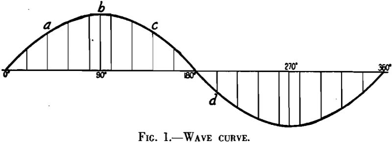
IDEAL JIG STROKE
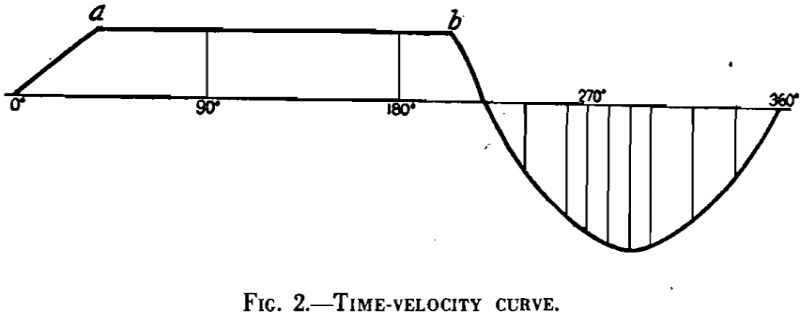
Since it is recognized that some jig strokes are better than others, it may be reasoned that a best or ideal stroke exists. Unfortunately, that is as yet unknown, but a stroke that comes close to embodying the principles discussed in this chapter is one proposed by Thomas.
This curve shows an initial rapid acceleration, then a period during which the acceleration ceases and the velocity becomes constant, which gives ideal conditions for a rapid opening of the jig bed, and finally a suction period in which the return of the water to the hutch compartment is effected by the pull of gravity. This may be considered a more or less theoretical curve and the details of an actual stroke may vary appreciably from the curve shown. For instance, it may be that a slight acceleration or a slight deceleration may be desirable instead of the portion of the time-velocity curve shown as horizontal. From an experimental standpoint, all that is known at present is that the closer it has been possible to come to this general type of stroke in operating commercial jigs, the higher has been the efficiency of the operation, efficiency being considered as capacity to handle a high tonnage of coal when the separation is simple, or to handle a difficult separation at some lower tonnage.
THE BAUM JIG
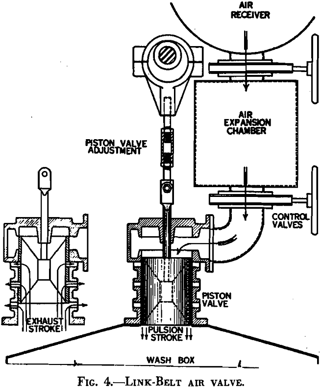
The distinctive feature of the Baum jig is the fact that the pulsations of water are produced with compressed air. The essential elements are few.
First is the jig box itself, which is U-shaped. On one side of the U, near the top, is a perforated screen plate on which the separation is effected and on the other side is a sealed chamber in which the air initiates the pulsations. The bottom of the U forms the hutch compartment and the U as a whole acts as a passageway through which the pulsations from the sealed chamber are delivered to the materials resting on the screen. The box usually is divided longitudinally into compartments and cells. A compartment is a complete jig in itself, for a multiple-compartment jig is in reality a series arrangement of two or more complete jigs.
Air Valve.— It contains two elements. One is a slide valve that opens and closes ports leading to and from the sealed chamber over the water; the other is a small auxiliary receiver, called an “air-expansion chamber,” between the main air receiver and the slide valve. Gate valves regulate the flow of air from the main receiver to the auxiliary receiver and from it to the slide valve.
INSTALLATION OF THE BAUM JIG
In the discussion to follow, a number of points are listed that should be checked on every new installation.
Pump.—The pump should have somewhat more capacity than necessary. In fact, it should have enough excess capacity so that with due allowance for wear it will still supply the requisite volume against the existing head after one year’s operation. It should be driven through a V-belt having a slightly larger motor pulley than necessary. If this practice is followed, the output of the pump can be varied somewhat to take care of any error in anticipating the requirement of water by the mere expedient of changing the size of the drive pulley on the motor.
Compressor.—The compressor should be a positive displacement type and should be driven in the manner just described for the pump. In this way the pressure and volume can be adapted to the actual requirements of the jig. The receiver should be equipped with a valve for exhausting the air. This can be opened or closed by the operator during starting and stopping by means of a series of levers or by means of a solenoid. The valve should be supplied with a stop that can be adjusted to leave a small amount of air on at all times when the jig is idling. This practice will keep the water from building up in the air chamber during short stops that occur from time to time in a day’s operation.
Once a bed of refuse is formed on the screen plates, some refinements may be attempted in the adjustment. Since the air and the water both contribute to the pulsion stroke, a proper balance between them is essential. That balance depends upon the conditions required for efficient cleaning. Every degree of mobility is possible, from a pure pulsion stroke in which practically no water returns to the hutch compartment on the suction stroke to one in which a bare minimum of upward-current water is used and a large amount returns to the hutch compartment. In the first case, little cleaning is done on the fine sizes; in the second, even very small sizes are efficiently cleaned.
If the top layers are breaking but the operator wishes to increase the mobility and also to increase suction, he increases the air with little or no addition of water. In fact, he may even reduce the water somewhat. If he wishes to decrease suction while increasing mobility, he will normally leave the air alone and turn on only water. In this way any degree of pulsion or suction can be obtained.
In all adjustments the operator must maintain mobility of the bed at the peak of the pulsion stroke. This is necessary and fundamental, even when strong suction is required. If the operator is in doubt as to the balance between air and water, he should err in the direction of too much water. In particular, he should use more water when the top layers are not opening. There is no merit in trying to save water in jigging. A certain amount of power is required to jig coal and that power might as well be supplied via the water pump as via the air compressor. The object is the best adjustment of the jig to clean the coal.
Adjustment of Float Controls.—After the refuse mechanism is in operation, the proper specific gravity of the float can be determined roughly by watching the refuse elevators. In general, as much refuse should be drawn in a given compartment as practicable. For that reason, the float should be adjusted to pull more and more refuse as long as the quality remains satisfactory. Changes should be made slowly, however, and plenty of time should be allowed (at least 5 min.) for conditions in the jig bed to come to equilibrium after each change. Also, from time to time it is important to check the mobility of the bed, especially if the depth of the refuse bed is being decreased, for the amount of air and of water can be reduced somewhat as the refuse bed is lightened.
Depth of Bed.—Depth of bed has been discussed in general in principle No. 7, but some practical limitations can be added. As a rule, other factors in a jigging operation limit the depth of bed to 12 in. minimum even on ¾-in. to 0 feeds. On the other hand, experience has shown that a feed 8-in. to 0 in size can be handled successfully with a 24-in. depth of bed. In other words, the relationship between maximum particle size and depth of bed is anything but a straight line.
OPERATING SUGGESTIONS FOR THE BAUM JIG
The Baum jig is one of the most foolproof pieces of equipment that money can buy, but it should have some attention. The following points should be noted especially:
- Screens should be inspected for cracks, leaks, and other defects at least once a week. If the jig is operated with strong suction to clean the small sizes, the screen plates should be examined once each shift. This is particularly true when very small perforations are being used.
- The elevator buckets and chains should be examined every shift while the jig is running, to catch damaged buckets, broken links, and the like.
- Proper lubricants should be used. Often parts of a jig, such as automatic controls, for example, require special greases or oils. Manufacturer’s recommendations should be followed religiously on such parts of the jig.
- The operator should not under ordinary circumstances be permitted to change adjustments of the jig without special authorization of the washery superintendent or preparation manager responsible for the quality of the washed coal.
- The matter of how best to handle short stops of 30 to 60 sec. is in a measure a special problem at different plants.
OTHER TYPES OF JIGS
Faust Jig
- It has plungers on both sides of the screen plate, which are accurately synchronized.
- The refuse is withdrawn through kettle valves near the overflow lips in the respective compartments. The kettle valve is of the dam-and-seal type. The seal, or outer wall, is a large pipe extending from above the water level to within several inches of the screen plate.
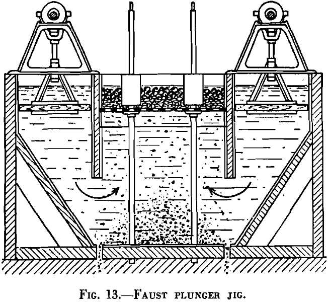
- The hutch is commonly discharged periodically by the operator by means of suitable hand valves operated from the working floor.
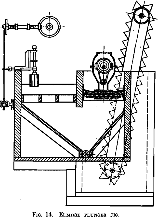
Elmore Jig
The Elmore is a plunger-type jig and may be either single or multiple compartment. The distinguishing features are:
- It has an automatic control in the form of a cylinder that measures the specific gravity of the mixture of coal and refuse. As the density rises, the float rises higher on each pulsation. When it reaches a certain level, a suitable linkage starts the refuse draw. It pulls refuse until the float drops back to the predetermined level.
- The refuse draw is a star gate under the overflow lip in each compartment, which extends the full width of the jig.
- The hutch commonly is collected with a screw conveyor and discharged through the refuse elevator. Water commonly is admitted under the plunger.
Denver Mineral Jig
The Denver Mineral jig is a diaphragm jig for fine material, having the following characteristics:
- An artificial bed of steel shot or other appropriate material resting on a nonblinding wedge-wire screen forms the bottom of the separating compartment. The heavy particles work through this bed and are removed as a hutch product.
- A rotating valve synchronized with the eccentric admits water into the hutch on the upward stroke of the piston only, so that the jig operates with little or no suction.
- Speed and stroke are adjustable between limits. Each screen compartment, with its steel-shot bed, can be easily removed as one unit and changed for another compartment.
- The jig is built with one or two compartments and in four sizes varying in compartment width from 8 to 24 inches.
The Denver mineral jig finds application in coal preparation for removal of sulphur from thickener underflow material prior to its treatment by froth flotation.
SUGGESTIONS ON INSTALLATION AND ADJUSTMENT
Virtually all the suggestions given earlier for the installation of a Baum jig—variable-speed drive, constant water pressure, ample supply of water, arrangement of water valves, facilities for inspection of refuse, and the like—apply equally well to all kinds of jigs.
The discussion on the principles of jigging and on the adjustment of a Baum jig also apply to all except a very few types of jigs. For instance, it should be noted that where an adjustment of air is involved on the Baum jig, the corresponding adjustment on a plunger-type jig is length of stroke. A few additional suggestions follow:
Initial Setting of Plunger Jig.—The initial setting of a plunger jig has been described as follows:
“When a jig is being started for the first time, the length of stroke and the quantity of water must be roughly set to get the jig in operation. For a preliminary setting on 1-in. coal, the total vertical travel of the plungers per minute may be set at 200 in. This figure divided by twice the number of strokes per minute gives the approximate length of stroke. For example, if 85 strokes are to be made per minute, the travel of the plunger per revolution of the eccentric will be 200 in.÷ 85 = 2.35 in. and the stroke will be 2.35 in. ÷ 2 = 1.17, or roughly 1¼ inches.
Many plunger jigs have float controls similar to those previously described for the Baum jig; hence, they require no further comment. However, kettle draws such as are used on the Faust jig should be discussed.


