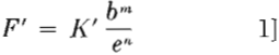
PRESSURE DROP STUDIES
For convenience in study, the problem was divided into two parts, cyclone pressure drop or energy loss, and solid elimination efficiency. The two divisions will be correlated at
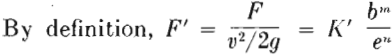
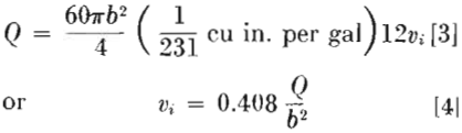
As this equation is difficult to handle and usually involves a trial and error solution, the following transformation was made.
 nd taking the square root gives
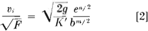
However, the gallons per minute of feed slurry is equal to
Substituting for υi in Eq 2 and rearranging, gives
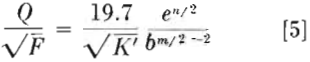
This equation can be further simplified by combining all constants and exponents to one symbol, as follows:
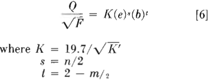
The term, Q/√F, has been designated as the capacity ratio and is the basic expression for any flow apparatus, i.e., capacity is a function of the square root of energy loss, and thus Q/√F should remain constant for any constant dimension apparatus. It will be observed that Eq 6 is expressed in simple terms, easily measured, and involving no trial and error in its use. Thus, if valid, it represents a rapid and easy way of predicting either capacity

or pressure requirements for any cyclone. It should be emphasized at this time that the term F represents the energy loss in the cyclone proper. In the complete installation, sufficient energy will have to be supplied to overcome all friction losses and potential and kinetic energy changes in the feed line and nozzle and overflow pipe and nozzle.
Taking the logarithm of both sides of Eq 6,
log (Q/√F) = log K + s log e + t log b…………………………………………………….[7]
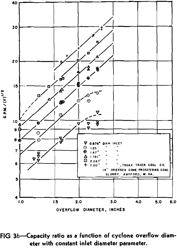
As K, s and t have been assumed as constants in the above derivation, Eq 7 represents a straight line if either e or b are held constant. Therefore, if the theory advanced is valid, a plot of capacity ratio as a function of one diameter with parameters of the other should yield straight line curves on log-log paper. Furthermore, all parameters of one set should be parallel with a slope of either s or t. The K value can be determined from the intercept value for capacity ratio where the variable diameter is equal to 1 in. by use of Eq 7.
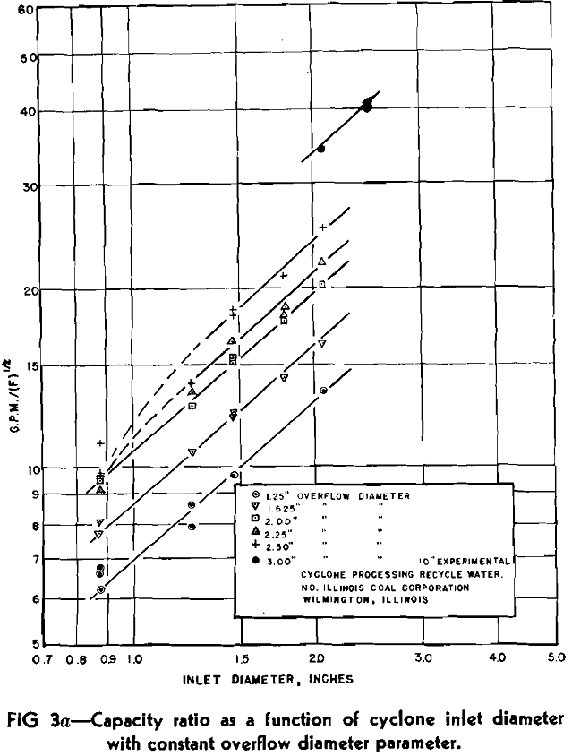

The slope of Fig 3a which equals the exponent t is 0.89, while that of Fig 3b which equals the exponent s is 0.9. For convenience, the exponent on both terms was assumed as 0.9 which introduces a negligible error. Thus, Eq 6 can properly be applied to any liquid- solid cyclone within the designated overflow to inlet diameter ratio as
Q/√F = K(eb)0.9…………………………………………………..[8]
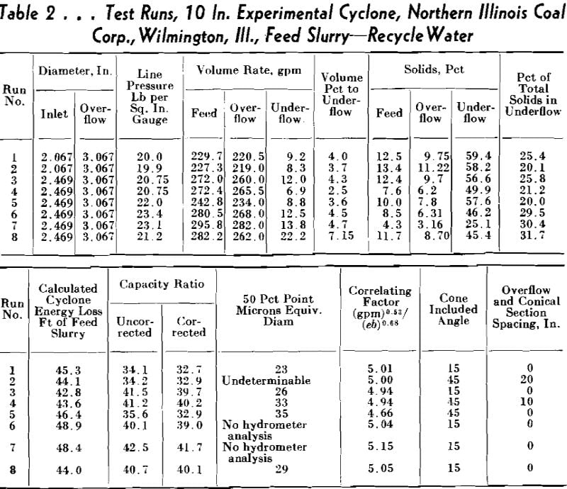
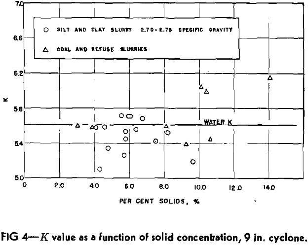
The average K value for the 9 in. experimental cyclone determined from the straight line portion of the parameters was 5.61. The range of variation was 5.47 to 5.73, with an average deviation of 0.079 or 1.4 pct. For the 9 in. cyclone, then
Q/√F = 5.61 (eb)0.9……………………………………………………………[9]
WEIGHT PERCENTAGE OF SOLIDS IN FEED
Several runs were made with varying solid concentrations in the feed to observe any effect of solid concentration on energy loss. As the line slopes of the industrial data in Fig 3a and b indicated that solid concentration had no influence on nozzle diameter exponents, any alteration of Eq 9 for the 9 in. cyclone would be found in the K value.
In performing the solid runs, two different types of slurries were used, the first being various coal and refuse solids, and the second a silt and clay material with a close gravity range of 2.70 to 2.75. Assuming Eq 8, K values could be determined for the various runs. However, these values were obviously too high, which seemed incongruous, especially as the feed slurry became more concentrated. Upon observation of the character of the underflow during operation, it was observed that the vortex discharge was considerably more vigorous as the dilution of the solids increased. Thus, it was reasoned that the solids discharged in the underflow represented a negligible amount of energy loss, and therefore should be omitted from capacity ratio considerations.
SEPARATION BETWEEN OVERFLOW AND CONICAL SECTION
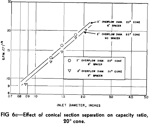
Because of the change in direction of the outer spiral at the base of the conical section, the placement of the overflow exit with reference to this point can be expected to have an effect on the capacity ratio. For the 9 in. cyclone, 3 and 6 in. cylindrical spacers, which could be inserted between the conical section and overflow point, were constructed. Capacity ratio tests with a parameter of constant overflow and one of constant inlet were made and results plotted in Fig 6a and b. Included in these log-log graphs are the same parameters obtained from Fig 3a and b for the 9 in. cyclone without spacers.


VOLUME PERCENTAGE REPORTING TO THE UNDERFLOW
Depending on the solid concentration, different volume percentages of the original feed may be discharged to the underflow. To determine this effect, several water runs were made with varying volume distributions between overflow and underflow.
CYCLONE DIAMETER
With the gas-solid cyclones, wall friction was found to be negligible, and consequently cyclone diameter had no effect on the K value. To determine the importance of this variable with the liquid-solid cyclone, a 7 in. cyclone on hand, and a newly constructed 3 in. cyclone were used. Both possessed included angles of 20°, and similar spacings between overflow point and conical section to that of the 9 in. cone without spacers. Water tests on these cyclones yielded the following K values, assuming Eq 8 to be valid: 3 in. cyclone, 5.55; 7 in. cyclone, 5.20.
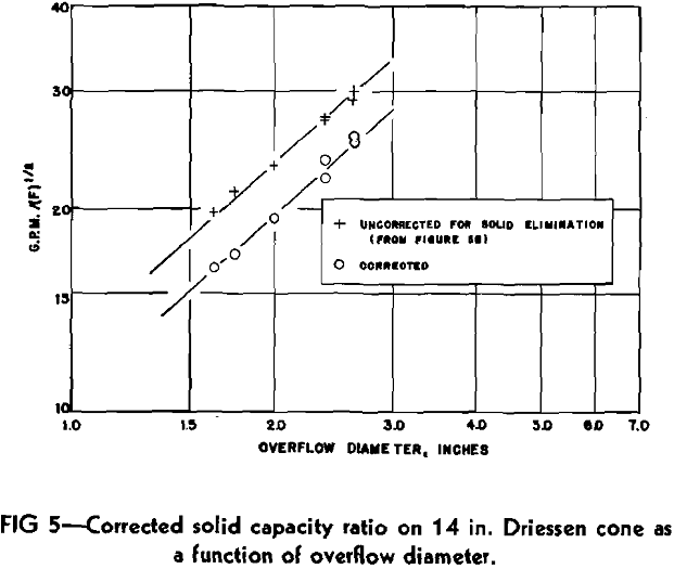
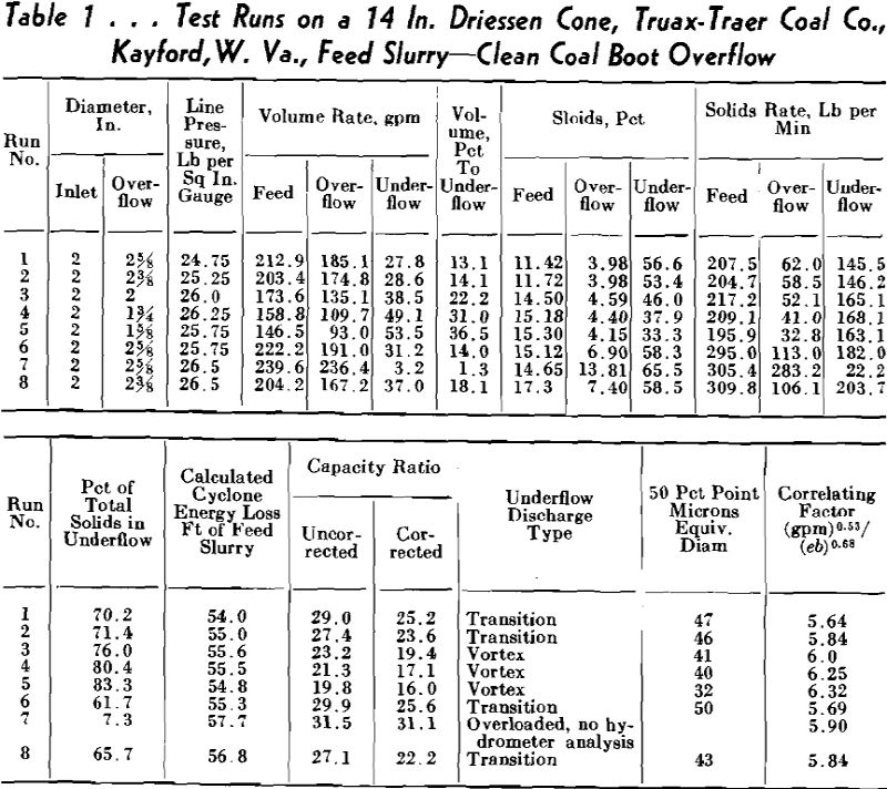
These compare very favorably with the 9 in. cyclone K value of 5.61. Solid runs on the smaller cyclones also yielded comparative values. As the 14 in. Driessen cone was similar in construction to the experimental cyclones, its K value is also of importance. Referring to Fig 5, the K value was determined from the line of the corrected data as 5.57.
FUNDAMENTAL CONSIDERATIONS
In attacking the problem, it was felt that the same three variables of major significance with regard to energy loss would be of similar importance in solid elimination efficiency. As inlet nozzle diameter decreases, entrance velocity increases for a constant throughput. Due to the spiral flow pattern, tangential velocity increases inversely with cyclone radius. Therefore it would seem proper to assume an increasing critical centrifugal force as inlet diameter decreased for a fixed capacity. By the same consideration, centrifugal force should also vary directly with volume throughput. Finally, with regard to the overflow nozzle, it is necessary to refer again to the gas-solid cyclone theory. It was found that the location of maximum centrifugal force occurred at a critical radius approximately equal to that of the overflow tube. By decreasing this radius centrifugal force should be increased.
To determine the extent of these various factors, elimination efficiency tests were made with the 9 in. cyclone maintaining two of the three variables constant during any one set of runs. The elimination efficiency was plotted against the variable factor on log-log
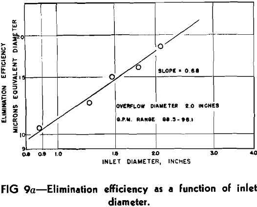

paper to ascertain if the effects were exponential functions. Fig 9a indicates elimination efficiency as a function of inlet diameter. During these tests, overflow diameter was 2 in. and the feed rate maintained at 88.5 to 96.1 gpm. Considering that experimental error probably limits determination of the 50 pct point to an accuracy of 1 micron, it appears that the inlet diameter either is or closely approximates an exponential function. The slope of the average line drawn in Fig 9a is 0.68 and equals the exponent on the inlet diameter term.
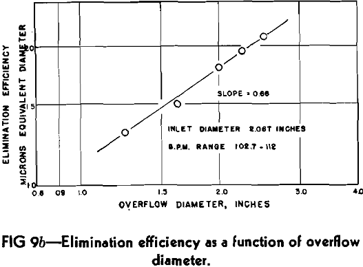
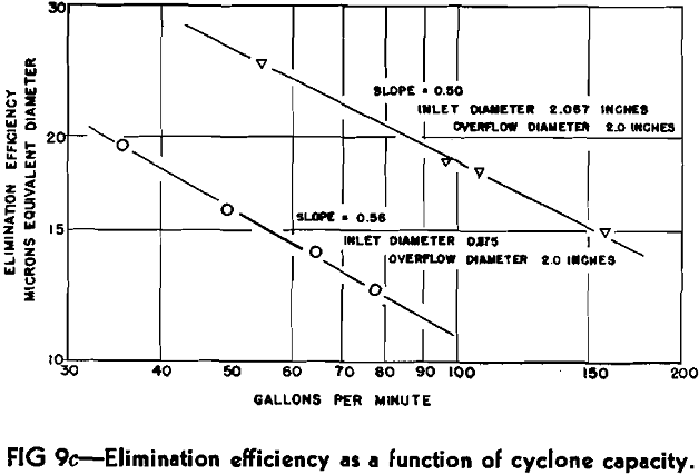
Fig 9b plots elimination efficiency vs. overflow diameter during which time the inlet nozzle was 2.067 in. and slurry rate varied between 102.7 and 112.0 gpm. An excellent straight line relationship was obtained with the slope being 0.68 as in Fig 9a.
CYCLONE DIAMETER
As centrifugal force is inversely proportional to the radius of curvature, investigation of cyclone diameter is mandatory for a thorough examination of elimination efficiency. Solid runs were accordingly performed on 3 and 7 in. cyclones. As the inlet and overflow diameters were fixed it was necessary to vary the volume throughput in order to obtain different values of the correlating factor. Resultant points are indicated on Fig 13 along with the average performance line of the 9 in. cyclone. All values lay within 1 micron of the average line or its extension indicating that cyclone diameter has a negligible effect on elimination efficiency as predicted by the 50 pct point. Furthermore the 3 in. cyclone points always lay above the average line while those of the 7 in. were below, a second indication of the unimportance of cyclone diameter.
W. E. Brown—In the operation of the cyclone, what factors have you found that will affect its results as far as efficiency goes; for example, if you have coming through the cyclone a pulp of 20 gpm, that has, say, 25 or 30 pct solids, and then from operational characteristics this pulp changes to 35 pct solids but it is still maintaining the same ratio of flow. How does that affect the cyclone?
D. A. Dahlstrom (author’s reply) —It has a definite effect, as you know from Mr. Sutherland’s paper, in that as you increase the solid concentration of your inlet slurry, you will naturally have an according effect on the overflow concentration. This, of course, assumes that the amount of addition possesses the same size distribution—in other words, the size distribution of the heavier load is the same as the lighter load. The cyclone will tend to operate with about the same efficiency even though there is an increase in the loading. A very rapid complete overloading of the cyclone is not usually experienced. However, it will undoubtedly tend to go into a transition dis-charge for severe loadings unless there is some method of changing the underflow diameter. In this case the recovery undoubtedly will be injured to a certain extent.
There have been methods advanced for the use of a rubber joint at the bottom of the cyclone in order to be able to change the diameter of the underflow at any one time. I have not done any work at all on that, so I cannot answer that question, but we believe it is extremely important that the slope of the cone be maintained constant all the way down to the underflow discharge. As soon as the flow pattern of the cyclone is disturbed, the air current, which we think is important for the maximum elimination of solids, tends to shut off.
J. D. Grothe—The work at the collieries would be on heterogeneous gravity solids. Can you tell us the effect in this case?
W. L. McMorris—You made the statement that the cyclone could be used as a vessel for separation for particles of different gravity. You showed in your slides a differential between the 50 pct point of your standard material and that of a higher gravity material. Have you ever worked out, either experimentally or mathematically, the difference in the ratio of concentration shown in the cyclone as compared to the ratio of concentration in hindered settling or in free settling ?
D. A. Dahlstrom—May I change your question around to this: Have we shown any effect on the 50 pct point as we increase the solid concentration on the feed—does that sound logical?
W. L. McMorris—No. Let me give you an example. You made the statement that there would be a different 50 pct point on pyrite as compared to 1.3 gravity coal. If you apply the standard hindered settling formulas to 1.3 coal and, say, 4.9 pyrite, would the ratio of concentration that you obtain in the cyclone be as good as that which you obtain in hindered settling?

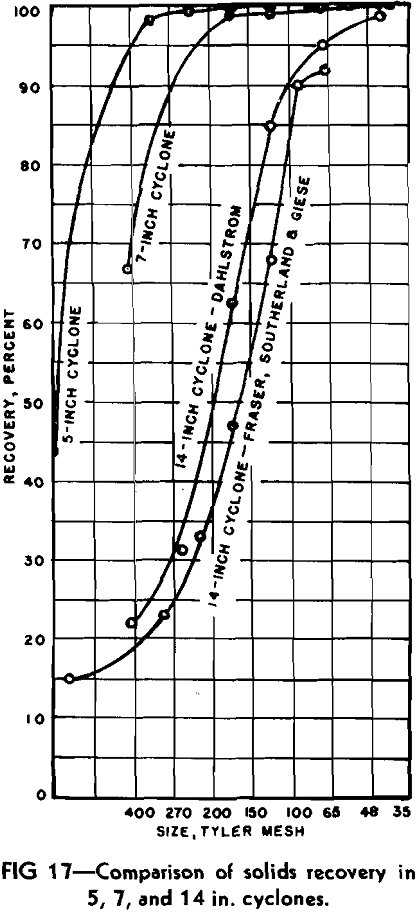
One of the most important conclusions he has reached is that cyclone diameter has no influence on the efficiency of recovering solids; in other words, large cyclones are as efficient as small units. This conclusion, however, does not appear to be substantiated by published data on cyclone performance, even including that provided by his own work.
Thus, while from a theoretical standpoint it may be possible to operate large cyclones at velocities high enough to give the high recoveries characterizing small cyclones, in the pressure range commonly used the larger cyclones are distinctly less efficient. This argument should not be construed, however, to indicate that multiple small units are necessarily to be preferred to a single large cyclone. The cost of producing small cyclones equaling a larger unit in capacity may be greater, and in some instances the attempt to obtain complete solids recovery may not be justified economically. The advantage of the small cyclone is stressed here to correct any misconception about the relative efficiency of large and small units. Equipment manufacturers should consider the feasibility of producing small cyclones in multiple units for applications where maximum solids recovery is a justifiable objective.
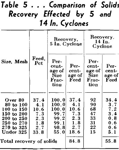
Another anomaly is evident in the fact that sedimentation tests indicated that 100 pct recovery was effected in the sizes coarser than 65 microns, whereas the actual screen-analysis data indicated that complete recovery was effected only in the sizes coarser than 20-mesh, corresponding to 840 microns. Obviously there is no direct correlation between the equivalent diameters obtained by sedimentation tests and sizes determined by screening. With discrepancies of this magnitude inherent in the sedimentation method, it is clear that conclusions reached on the basis of its use must be regarded with great caution.
The portion of the curve below 270 by 400 mesh for the 5 in. cyclone and that below 140 by 200 mesh for the 7 in. cyclone was obtained entirely by extrapolation. This means extrapolating a curve established only from 100 down to 98.3 pct in the former case and to 98.9 pct in the latter, making any extension subject to considerable error. The curve representing the author’s data on the 14 in. cyclone included 4 runs operating with a transition type underflow discharge in the 5 run average which were originally maintained to be inferior. The fifth run operating with a complete vortex discharge was definitely superior (run 3, Table I in the paper) with a 76 pct recovery of the total feed solids.
In regard to percentage of water entering the cyclone underflow, the author also believes that it does have a bearing upon the final recovery of solids. However, it is maintained that this effect is insignificant after a complete vortex discharge has been attained.