MOZLEY SUPERPANNER: LABORATORY MINERAL SEPARATOR TABLE
US:
Rapid separation of mineral grains for mineralogists, metallurgists and mill operators. The 911C800 Laboratory Mineral Separator is a valuable tool for metallurgists, mineralogists and mill operators. It quickly and efficiently separates mineral grains of close specific gravity.
The Superpanner is a Mechanism invented by Professor H. T. Haultain which simulates rocking,bumping, and sluicing action used in panning, and gives precise information as to possibility of gravity treatment of sands. Used in rapid assays and as a research aid.
Tabling tests can begin with individual treatment of each size from about 50 mesh down to, say, 20um on a Haultain superpanner. If material can be concentrated by gravity methods (tabling, vanning, and spiralling included), it can be concentrated on a superpanner. If this instrument fails, no commercial method will succeed on fine sizes. The super-panner is a miniature shaking table into which are built most, if not all, of the motions used in panning. A sample of a few grams can be tested, or some hundreds of grams can be worked in successive additions and particle removals. There is, in fact, no great virtue in using more than a light charge when testing for a gravity process, but bigger quantities are treated when search is being made for particles of heavy minerals only present in very small amounts. The advantage to the microscopist of being able to examine a sample of, say, half a gram which should contain all the heavier minerals from a total of half a kilogram are obvious. Any desired texture of decking can be used on the superpanner, linoleum and stainless steel being sufficient for most work. Adjustments are for side and end shake. slope, bump, stroke length and speed, and sluicing water.
A most effective instrument and it has always been a puzzle to me that it is not been universally used by millmen.
It incorporates an improved shaking mechanism and a non-porous deck through which a cyclic pulse of jigged water is applied, thus stratifying the test material. If superpanner tests are favourable, a suitably classified feed is run over a miniature shaking table. The usual settings for a commercial machine are applied, attention being given to rate of feed and to pulp consistency.
Typical Applications
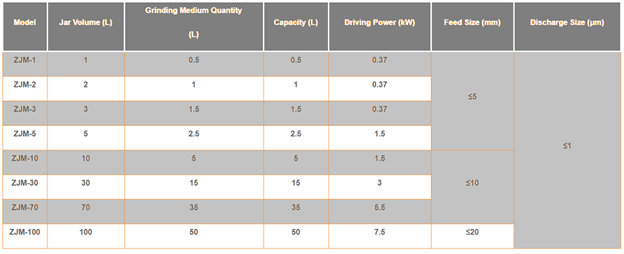
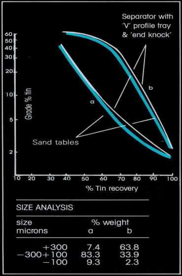
The separator is supplied with two easily interchangeable stainless-steel trays enabling efficient separation over a wide size range.
The ‘V’ profile tray with ‘end knock’, when treating closely sized material, is capable of not only of duplicating heavy liquid analysis results, but of giving additional data in the higher SG ranges. The separator is therefore ideally suited to carrying out release analysis.
The ‘V’ profile tray with ‘end knock’ is able to accurately predict sand table performance when treating hydraulically classified products.
This is of great value in optimization of plant performance.
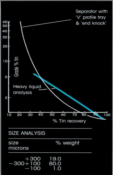
The flat tray is capable of making very efficient separations of samples finer than 100 microns. This is of value in predicting slime table
performance or carrying out release analysis where fineness of the material precludes heavy liquid analysis.
Applications
Gold
Silver
Platinum
Cassiterite/Tin
Tantalite/Tantalum
Wolframite
Scheelite
Metal-bearing sulfides
Zirconium
Titanium minerals
Chromite
REE
Grade/Recovery Analysis of the Laboratory Mineral Separator Table
Interpretation of test data may be carried out visually, microscopically or by assay analysis of the separator products. If a complete grade versus recovery evaluation is required a series of consecutive samples is collected during the separation. At the completion of the run of the product remaining on the tray is divided into middlings and concentrate to be collected separately. All samples are dried, weighed and assayed and a grade versus recovery curve plotted from the results.
Laboratory MOZLEY Mineral Separator Flat Tray # 1
Mozley Table Superpanner V Tray # I
Laboratory Mineral Separator Flat Tray # 2
Product gallery
SUPERPANNER WORKING PRINCIPLE
LABORATORY MOZLEY MINERAL SEPARATOR EXPERIMENT
The Superpanner took form as illustrated in Figures 1 and 2. The essential features are a suitably supported pan of special shape, 30 inches long and 10 inches wide, and a mechanism which permits of many adjustments being quickly and readily made while in operation. The pan is a sheet of aluminium, to which has been firmly cemented a special linoleum made for me, after considerable experimentation.
This pan is bent with a gradually decreasing radius of curvature. The mechanism provides an end bump, like the old Gilpin County bumper, and a gentle side shake. The mechanism permits of the following adjustments:
The slope of the pan
The intensity of the end bump
The length of stroke accompanying the end bump
The number of strokes per minute
The amplitude of the side shake separately for each end of the pan
The number of oscillations per minute
The amount of wash-water
The depth of the pool in the rear end of the pan
This sounds very complicated, but the adjustments are very easily made while operating, and generally only three of them are much used, namely, the slope of the pan, the speed of the end bump, and the speed of the side motion.
The principle of operation is that the end bump tends to move forward the mass of sands on the pan, while the wash-water and the side motion tend to wash the surface particles to the lower end. The heavier concentrates, finding their way to the surface of the pan, come to a fine tip, where they can be removed by means of a small suction pipette. The excess water and tailings are removed by continuous suction through the tube at the lower end of the pan. A bottle is interposed in this suction so that the tailings can be collected without loss. The position of the suction tube governs the depth of pool in the lower end of the pan, which is generally reduced as the process continues. The mechanism is driven by two small independent electric motors, each with its own rheostat. One operates the end bump and the other the side motion, so these two are kept independent of each other. In the latest form of Superpanner, simple air motors take the place of the electric motors.
A really essential feature of the operation is the human element and the development of the necessary technique. As changes are made in the adjustments, the results show quickly on the pan and the operator soon realizes how to get the desired results.
There are three types of results obtainable:
The recovery of very minute quantities of concentrates, such as free gold or tellurides. Free gold can be found in all the tailings from the Kirkland Lake district, even after intense cyanide treatment. Tellurides, when existing in the proportion of one part in ten-million, are readily recovered. The osmiridium of the Rand banket, existing in probably less than one part in fifty-million, can also be recovered.
The recovery of a larger amount of clean concentrates, such as pyrite free from tellurides and free gold, or galena from a mixture of zinc-lead middlings, or the separation of pyrite from arsenopyrite.
The separation of gangue from sulphides, that is, the recovery of clean tailings, for example, from flotation tailings.
The range of sizes that can be treated is from 65-mesh down to 14 microns. In some work, still finer material can be treated, especially if the feed has been sized by the Infrasizer. Simple separations can be completed in a few minutes. When dealing with extremely fine material an hour or more may be required, but the Superpanner may be left to run itself after adjustment. The paper entitled Milling Investigations into the Ore as Occurring at the Lake Shore Mines, by Blomfield and his Staff, states:
The Superpanner produces good quantitative results down to at least 14 microns and occasionally to 10, and qualitative results on all sizes.
Fine & coarse table feeds from tin plant
Cassiterite bearing beach sand
‘Slime’ product from tin plant
Description of Mozley Mineral Separator: For the pre-concentration of heavy minerals use of flowing film concentration units like tables spirals/richert cones etc. is becoming inevitable. In selection and sizing of such units use of Mozley Mineral Separator plays a vital role, since it separates mineral grains having close size ranges or specific gravities efficiently and depicts the influence of operating and design parameters in true sense.
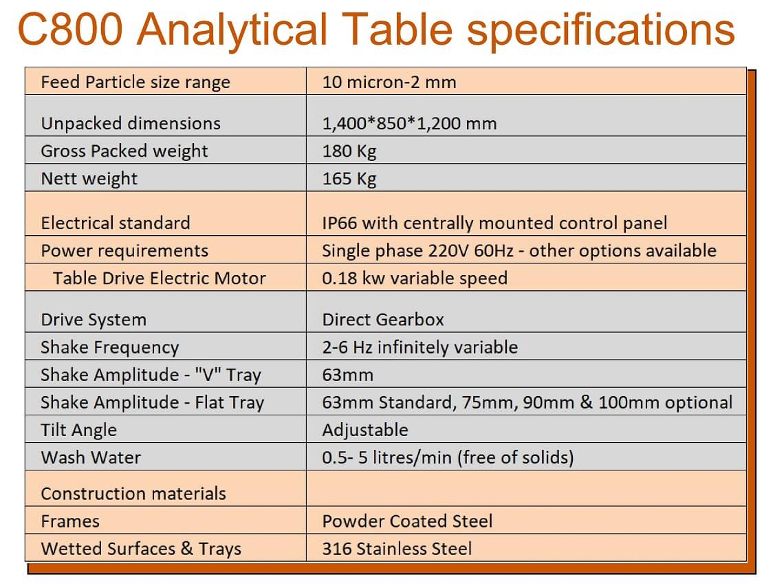
The Laboratory Mozley Mineral Separator is capable of treating particles from 2mm to 100µm particles arc generally treated on ‘V’ profile tray and less than 100µm size particles arc treated on flat tray.
Since it is laboratory-testing device, it is having batch process. It is an extremely useful tool for rapid, testing of amenability of ore minerals for their bencficiation using flowing film devices on small scale. The plant size separators can be upstaged from the data generated. The operating principle is however incorporated into a plant-size of the machine.
Material Preparation: About 300 kg Beach Sand was collected. The collected sample was sampled to reduce its bulk to 100gms using Jones Riffler, from which about 30 packets each weighing 100gm was obtained. Feed characterization studies on this sample was performed by conducting size analysis and size-wise sink-float analysis. The results of the size analysis tests are given Table 2.
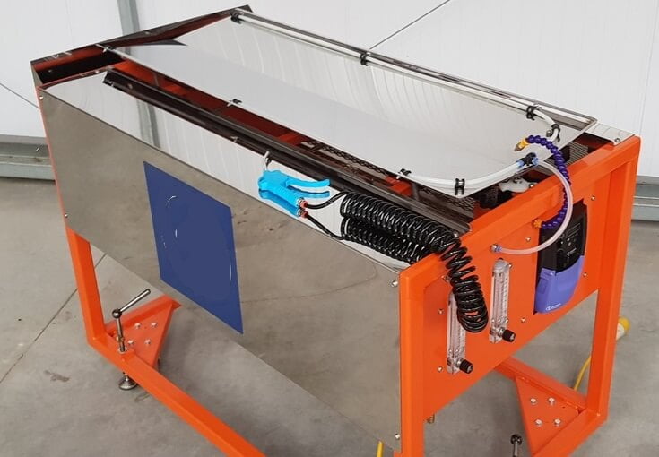
Experimental Set-up: The Laboratory Mozley Mineral Separator is capable of treating particles from 2mm to 100µm particles are generally treated on ‘V’ profile tray and less than 100µm size particles are treated on flat tray. However for the present case flat type of tray was selected for the experimental work. This tray is nothing but a stainless steel flat surface inclined at a shallow angle to the horizontal in the longitudinal direction. The tray is oscillated horizontally in a direction of 90° to the maximum slope, crank driven via pulleys by motor. Separation of particles is carried out after placing the wetted sample on the tray near upstream end. On starting the separator the sample collects into a narrow band along the apex of the flat tray. The particles are kept in motion by the action of the separator. High-density particles sink to the tray surface and are thrown towards the upstream end of the tray by the knocking action. Low-density particles are carried down the tray by the flow of irrigation water to discharge via the launder.
Experimental Procedure: To start with, slurry of 100 gm sample was prepared in a 250 ml beaker and the same was pored on to the deck after fixing the levels of the variables at desired levels. Amplitude of 3.5 inches, number strokes of 100 strokes/per minute and inclination of 1.15° were kept constant in all these experiments where as the irrigation water level was changed at four levels (of 2.0, 2.2, 2.6 and 2.8 litres/minute) while performing experiments. For each level of water flow rate, influence of oscillation/retention time varied at four levels of 1, 2, 3 and 4 minutes was studied. Thus a total 16 experiments were performed in the present study. For each experiment, concentrate (remaining on the deck) and the tailing (flown out of the tray) were collected at the end of the desired oscillation time intervals fixed. These samples were later dried, weighed and used for the analysis purpose. Further, for each of the concentrate and tailing samples thus obtained after experimentation sink-float analysis tests were performed using Bromoform as the heavy liquid. These results are used for the performance analysis of the separator in terms of misplacements, which are discussed in the subsequent headlines.
Results and discussions: The results obtained from the tests performed on Beach Sands using Mozley Mineral separator are tabulated in Table 3. The following are the important discussions that can be made on these results.
1. Fig. 1 has been plotted to illustrate the effect of time on yield of concentrate (minerals material remained on the deck), it can be noted that as the time given for oscillation of deck (at a fixed inclination and amplitude) increases, the yield of concentrate decreases almost linearly. However, the rate of decrease in yield of product is dependent of the level of the water flowrate maintained at that instant. Observing the steepness of the curves, it is to be noted that with increased water flowrate (from 2.0 lpm to 2.8 lpm) the steepness of the plots plotted increases correspondingly. This is evidenced from the slope of the lines in Fig. 1.
2. Fig. 2 is plotted to depict the quantum of lighter fraction of feed material that is pure sand reporting to reject stream selectively. For this analysis, the reject (and concentrate) product of the Mozley Separator obtained at different time intervals of collection were subjected to sink-float analysis using an organic liquid (Bromoform sp. gr. 2.9). The float and sink fractions thus obtained after float sink analysis were used to represent the yield of heavier and the lighter fraction to the concentrate and tailing streams. The results are tabulated in Table-2 for different experimental conditions. Fig. 2 has been plotted using Cumulative time on X-axis of reject against Cumulative weight % of lighter fraction reporting to reject stream on the ordinate.
It is interesting to note that with prolonged collection of reject material up to 4 minutes with incremental time interval of 1 minute, the proportion of sand particles reporting to reject stream selectively increases simultaneously. However, a linear increase in the proportion of sandy particles to the reject stream is noticed for experiments carried out with water flowrate of 2.0 and 2.2 Lpm. Whereas, for the experiments carried out with higher water flowrate of 2.6 and 2.8 Lpm an exponential variation in the proportion of sand particles selectively reporting to reject stream is noticed.
Fig.3, illustrate the amount of heavier minerals reporting to the reject stream. From this figure it can be noted that up to 2 minutes of oscillation period no misplacement of heavies into the reject takes place and is independent water flow rate. Whereas, after two minutes of oscillation period the percentage of heavies to get last in the tailing stream is very large and becomes highly sensitive to the proportion water flow evidenced from the parabolic nature of the curves.
Fig.4, depicts the influence oscillation time on the total misplacement, which is nothing but the sum of heavies into reject and lights into the concentrate expressed in percentage. From the nature of the plots shown it is worthwhile to mention that, a complete reverse trend in the total mis-placement of material taking place is noticed when compared to the plots of shown in Fig.3. This is because, with prolonged oscillation time of the deck, although there is some loss of heavies into the reject (after 2 minutes of time) but complete rejection of sandy particles from heavies does not occur. This emphasis that for the production quality product we must keep the retention time for the particles more closer to 4 minutes with high water flow rates (at least 2.60 lpm), as noticed from the asymptotic nature of the curves obtained for 2.6 and 2.80 Lpm of water flow rates.
Conclusions:
From the discussions made above the following are the important conclusions that can be drawn for the beneficiation of Beach Sands
An increased retention time of particles reduces the yield of concentrate containing heavy minerals almost linearly in which the rate of decrease is based upon the amount of flow rate of water on the deck
The rate of removal of reject sand from heavy minerals is found to vary with respect to the water flow rate in the following manner:
a. A linear variation with 2.0 – 2.2 lpm
b. Exponential variation with 2.6 – 2.8 lpm
For the production quality product it is necessary to give the retention time for the particles more closer to 4 minutes with high water flow rates (at least 2.60 lpm)
However, the above conclusions are highly subjective and need further experiments to be carried out (by varying other variables like deck inclination, length of stroke etc.,) for the confirmation of the above conclusion.
The Mozley Laboratory Mineral Separator is capable of treating particles below 2mm size. It is basically a laboratory testing device operated in batch process. For establishing applicability of flowing film gravity concentration processes and fixing their operating parameters use of this separator is found be extremely important. It not only determines the feasibility of the process but also simulates an industrial unit at laboratory stage. For rapid testing of the amenability of ore minerals for their beneficiation using flowing film gravity concentration devices such as tables, spirals and richert cones etc, use of this unit is found be the most convenient.
A similar attempt has been made to determine the use of applicability of flowing film gravity separators for the for the separation of total heavy mineral form the beach sand collected. The tests carried out are mainly aimed at determining the retention time for the particles to obtain optimum performance. Therefore, a series of 16 tests were performed by varying water flow rate and the shaking lime at different levels, each varied at four levels of 2.0, 2.2, 2.6 and 2.8 Litres/min and 1, 2, 3 and 4 minutes respectively.