Metallurgists & Mineral Processing Engineers
For its extensive practical experience, 911 Metallurgist has a clear understanding of what successful mineral processing engineering is and how to go about achieving it. Your goal is the production of a material that is marketable and returns you and your investors sustainable revenues.
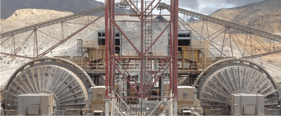
Although improvements to the metallurgical processes have been made over the years the fact is that the unit operations, the machines, those too often called “black boxes” involved have not evolved or changed much since inception. Ore is reduced in size, chemicals are added and minerals separated and upgraded to produce a marketable product. Much of this process is mechanical and generally mistaken for some dark alchemy. We are the Anti-Alchemists.

Our vast experience has been gained through the operation and start-up of both small and large-scale mining/metallurgical operations in a range of commodities in the base metals (Cu, Pb, Zn) and the precious metals (Au, Ag,)
A solid metallurgist understands the most important aspect of an operating process is its stability. Simple to say, but generally the most ignored in mineral processing. Linked unit operations require each to be stable, and each contains a different set of variables that have to be contended with. Thanks to some degree of stability: operating changes can be made and evaluated, increases in throughput can be made, and equipment performance can be improved. The more complicated the processes become, the more difficult it is to achieve and maintain stability. In mineral processing, unlike most processing operations, we have limited control of the main input, the feed ore. In most cases, this is inherently variable and usually outside the processor’s control.
Because you are too close to your own story, you might not see the forest for the trees and have chaos mistaken for stability. We, you, and your group have been battling plant problems for weeks, you start to accept chaos as a daily state of affairs and consider it your new stability.
911 Metallurgist can enter the scene and see what you have become blind to. We can fix issues in ways you never thought possible. Our fresh eyes will open new opportunities for your plant.
Each mineral processing plant has varied ore types, mining equipment, (crusher, ball mill, flotation, tailings), and management (operating) philosophy. The evaluation and prioritization of variables that affect the plant’s performance is the primary function. Implementing changes within the constraints imposed can be difficult, as resources may be limited.
Invariably the ability to solve problems can be confusing due to the large number of variables that may impact the processes. In most cases, problems are not metallurgical in nature but rather operational and mechanical. Problem-solving is a process, and in many operations, this ability is absent. All too often,
many changes are made together without a solution resulting, on more confusion. Most plants learn to live or survive their problems, not to solve them.

The primary strengths of our metallurgists are in Grinding and Froth Flotation Systems in which we:
- Evaluate process and ore resources.
- Prioritize problems.
- Evaluate resources available to resolve issues.
- The never-ending pursuit of process stability.
- Implement incremental changes, one at a time, towards improving stability and production targets.
- Educate personnel to ‘think’ before problem-solving along with a stability philosophy.
- Avoid top-down management solutions to process problems.
- Encourage the attitude that other groups within the organization are responsible for servicing the metallurgical process plant towards obtaining production objectives.
- Ensure that there is adequate planning for all groups, as this plays a vital role in the longer-term achievement of goals.
SERVICES OFFERED BY 911METALLURGY CORP
Our engineering team has global experience in the mining industry across all facets of the mine life-cycle. Our focus is to add value to your project and company by understanding your needs, employing innovative ideas, and applying sound engineering while maintaining an economically driven approach. We have a combination of senior-level professionals, experienced project managers, and technical staff to execute projects efficiently. We work in a partnership with our clients to achieve their company goals and operational milestones in a timely and cost-effective manner.
We provide comprehensive mining consulting services with international experience and technical excellence through a low corporate overhead approach.
OUR GENERAL OFFERINGS INCLUDE:
- Geology Mapping and Modeling
- Hydrology
- Resource and Reserve Estimation
- Open Pit and Underground Mine Design
- Mine Planning and Optimization
- Financial Analysis and Constraint Modeling
- Metallurgical Design and Process Flowsheet Development
- Process Audits
- Heap Leach and Tailings Design
- Mine Waste Facility Design
- Geochemical Risk Mitigation
- Geotechnical
- ARD Auditing, Mitigation, and Closure Planning
- Field Investigations
- Site Water Management; Groundwater Modeling and Overall Project Water Balanced
- Project Due Diligence
- Land Management
Details of our services by area:
GEOLOGY
- Geological, Structural, Fault, and Seismotectonic Mapping
- Exploration Sampling Program Design (Quality Control/Quality Assurance)
- Exploratory Data Analysis
- 3D Geological and Structural Modeling
- Mining Geology Modeling
- Collapse Gravity Structures Modeling
- Slope Stability and Seismic Hazard Analysis
RESOURCE/RESERVE ESTIMATION
- Exploration, Resource, and Production Database Creation and Management
- Creation of 2D and 3D Geology, Structure, and Resource Models
- Statistical and Geostatistical Analyses
- Geometallurgical models and Non-parametric Statistics
- Resource Estimation and Classification
- Due Diligence Review
- Metal Accounting and Production Reconciliation
- Tools include Vulcan, GEMS, Datamine, Techbase, Leapfrog, Sage, Micromodel, Carlson, Access, R, Python, etc.
- NI 43-101, JORC, SEC Compliant Reports
PROJECT VALUATION AND OPTIMIZATION
- Independent Project Review
- Project Due Diligence
- Independent Engineer
- Multi-Scenario (constraint analysis) Economic Modeling
- Project Optimization and Trade-Off Studies
- Scoping Studies / Preliminary Economic Assessments, Pre-Feasibility Studies, Feasibility
- Studies
- Technical Reports (NI 43-101, Guide 7, JORC)
- Pre-Feasibility and Feasibility Study Management
- Independent Advisor and Consultation Service
MINING ENGINEERING
- Open Pit Mine Design, Planning, and Engineering
- Underground Mine Design, Planning, and Engineering
- Operations Auditing and Optimization
- Mine Production and Cost Optimization
- Long Range, Mid-Range, and Short-Term Planning
- Mining Economics and Finance
- Material Handling System Design
- Reclamation Bond Calculation
- Underground Rock Mechanics – Field Investigations and Modeling
- Pit Slope Stability – Field Investigations and Modeling
- Underground Mine Ventilation
- Corporate Management – interim executives and production staff
- Safety Audits
- Practical Safety Plan Development
- Environmental Audits
MINERAL PROCESSING
- Test Work Design and Supervision
- Project Design
- Intellectual Property Development/Management
- Operator Training
- Technology Applications
- Financial Modeling
- Heap Leach Pad and Tailings Facility Design
- Flowsheet Development and Design
- Operating and Capital Cost Estimation
- Plant Auditing, Optimization, and Trouble Shooting
- Equipment Selection
- Equipment Optimization: Rock crushers, Ball Mills circuits, flotation circuits.
- Laboratory Design: Layout and equipment list, process streamlining using samples ovens, jaw crushers, Pulverizers, laboratory pressure filters, drying ovens, sample splitters, and assay furnaces.
MINE WASTE MANAGEMENT
- Tailings Dam Design – Rockfill, Earthfill, Upstream, and Downstream Construction Methods
- Dry Stack Tailings Design
- Waste Rock Facility and PAG Encapsulation Design
- Geomembrane Liner System Design
- Technology Screening and Risk Assessment
- Tailings and Mine Waste Co-Disposal Design
- Slurry Pipeline System Design
- Seismic Hazard Evaluation
- Geotechnical Stability Analysis
- Geochemical Characterization and Modeling
- Unsaturated Flow (Mine Waste Leachate) Modeling
- Mine Waste Cover Design and Modeling
- Tailings Dam Operations Support
- Dam Safety Inspections
- Monitoring Instrumentation Design and Installation
GENERAL CIVIL AND GEOTECHNICAL
- Site Grading and Drainage
- Geotechnical Instrumentation
- Foundations
- Access Roads
- Retaining Systems, Tie Back, and Soil Nail Wall Design
- Rockfill and Slope Stability Assessment and Mitigation
- Erosion Control and Best Management Practice (BMP) Plans
- Training For Safe and Environmentally Friendly Operations
- Seismic Monitoring Stations
HYDROLOGY, HYDRAULICS, AND WATER RESOURCES
- Piping and Pumping Systems
- Surface Water Management Plans
- Channels, Ditches, and Diversions
- Sediment Detention Structures
- Weirs and Flumes
- Stilling Basins and Energy Dissipation Structures
- Dambreak and Floodplain Studies
- Channel Restoration
- Stream Gauging Stations
- Meteorological Stations
- Site Climatology
- Site Hydrology and Hydrogeology Studies
- Pit Dewatering
- Groundwater Modeling for Mine Impacts
- Groundwater Supply Development
- Water Balance Studies
- Monitoring Well Design and Installation
- Vibrating Wire Piezometer Design and Installation
CONSTRUCTION SUPPORT SERVICES
- Owner’s Engineer
- Engineer of Record
- Construction Quality Assurance
- Construction Management
- Project Management
- Geotechnical and Materials Testing
- Post-Construction Monitoring
- Trouble Shooting and Remedial Action
- Instrumentation Monitoring
ENVIRONMENTAL MANAGEMENT & SOCIAL RESPONSIBILITY SERVICES
- Acid Rock Drainage (ARD) Prevention and Mitigation
- Reclamation and Closure Planning
- Environmental Studies – (Impact Studies, Baseline Studies, and Geochemical Studies)
- Environmental Management Planning
- Environmental Permitting
- Geofluvial Reclamation Design
- Sustainable Surface Water Management Plans
