Table of Contents
The technology of acid mine drainage (AMD) treatment has improved since the mid-sixties, and water pollution from active coal mining operations has been reduced considerably. Present treatment processes are designed to raise the pH of the effluent to within the range of 6.0 to 9.0 and reduce the total iron concentrations to less than 7 mg/l. However, in meeting these effluent standards, large volumes of iron hydroxide sludge are produced. Moreover, Federal laws require treatment of acid mine water as long as the acid conditions exist; therefore, sludge production will continue as long as the water must be treated, even though mining operations have ceased. Thus, solving one problem has generated another—the disposal of the AMD treatment sludge. The disposal of the water treatment waste is a serious problem because of the nature of the sludge itself and because there are not enough sludge disposal sites to handle the large amounts of iron hydroxide sludge produced annually.
As part of the Bureau of Mines’ environmental control program, a study was made to (1) determine the magnitude of AMD sludge production, (2) investigate current disposal practices and the extent of their use, and (3) assess these disposal practices. The study is based on data from 33 AMD treatment plants operated by 11 western Pennsylvania companies. Certain limitations were encountered. Only a few of the coal companies surveyed kept records of actual sludge production, some coal producers were unable to provide accurate data because of difficulties associated with the treatment process and/or changes in mine water quality. Therefore, certain assumptions (for example, percent solids of AMD sludge, weight-percent of mine water treated that resulted as sludge, and specific gravity of iron hydroxide) were necessary to calculate sludge volumes. The basis for these assumptions is discussed later.
This report examines the properties of AMD sludge, neutralization agents currently in use, and current mine water data for the water treatment plants surveyed. The magnitude of the sludge disposal problem and the observed disposal practices, including the extent of their use by industry, are described. Based on this information, recommendations for further research are made.
Properties of Mine Drainage Sludge
Physical Properties
The physical and chemical properties of mine drainage sludge vary according to the nature of the drainage water, the treatment process, and the neutralization agent. The choice of disposal method greatly depends on the physical properties of the sludge. The most important physical characteristic is the sludge settling behavior or “sludge settleability,” which includes both the settling rate and the final sludge volume. Several studies have investigated the influence of the neutralization reagent on the sludge settleability. These studies concluded that carbonates produce a “granular dense sludge,” as compared with the more “gelatinous voluminous floes” produced with a hydroxide. Thus, the fastest settling rates occur when the reagent is limestone, followed by sodium carbonate, milk of lime, and caustic soda.
Results of the studies indicated that limestone is a more effective reagent than lime since it has a high settling rate and produces a denser sludge. However, when the discharge waters from plants using the two reagents are compared, lime produces the clearer effluent. With lime, the ferrous iron in the drainage water is converted more completely to the ferric state and precipitates, with a well-defined interface between the sludge and the clear supernatant liquid. When limestone is used, even though the settling rate is faster, the oxidation reaction is slower, resulting in ferrous iron remaining in solution and the discharge of turbid water.
Chemical Properties
The chemical composition of AMD sludge also plays a role in sludge disposal. It is highly variable and nonuniform. The sludge is generally composed of hydrated ferrous or ferric oxides, gypsum, hydrated aluminum oxide, varying amounts of sulfates, calcium carbonates, bicarbonates, and trace amounts of silica, phosphate manganese, titanium, copper, and zinc. Ferric hydroxide, the major component, is largely responsible for the poor settling characteristics of AMD sludge. The hydrous nature and electrostatic charge of ferric hydroxide hinders sludge compaction. Ferric hydroxide results from the oxidation of ferrous hydroxide or the oxidation and hydrolysis of soluble ferrous iron. Appreciable formation of solid ferric hydroxide begins at a pH of approximately 4. Acceptable residual concentrations of iron in solution are generally achieved in the pH range 6 to 7.
Methods of Treatment
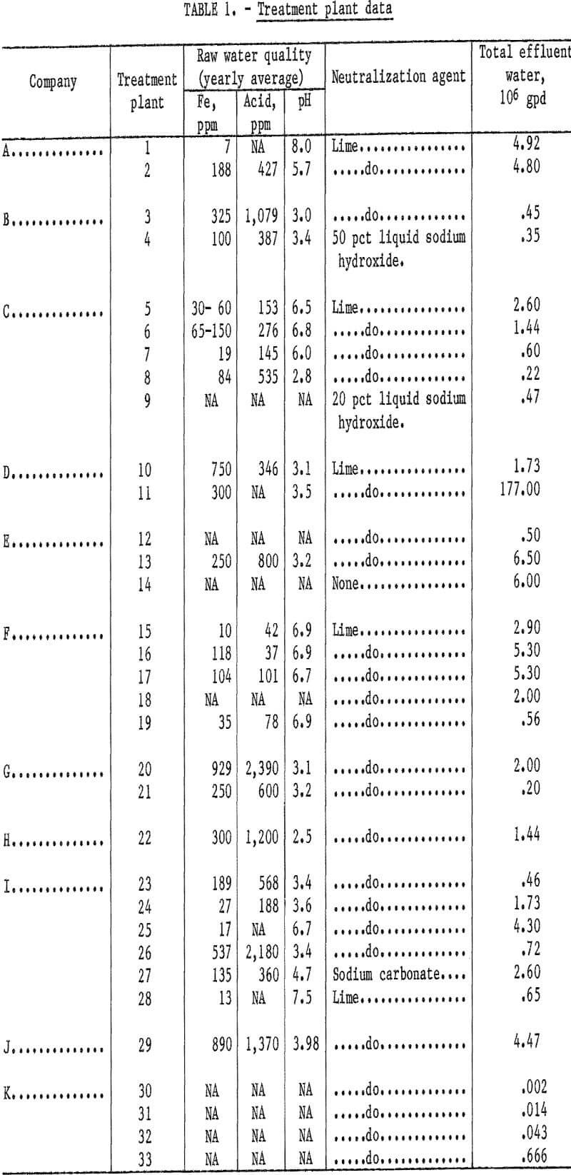
The voluminous ferric hydroxide component of the AMD sludge represents 15 to 30 pct of the treatment plant inflow. The AMD sludge is not readily nor economically dewaterable, so that handling and disposal become a significant problem. No mechanical dewatering devices were encountered in this survey. The following methods of mine water treatment were observed. Twenty-nine of the thirty- three treatment plants surveyed used milk of lime, purchased as a dry calcium oxide (CaO) or calcium hydroxide (Ca(OH)2), to treat their mine waters. Two treatment plants employed liquid sodium hydroxide; only one plant used sodium carbonate. One plant reported not using any reagents to neutralize mine waters, and needing only aeration to settle out the ferric iron. None of the plants used limestone. Table 1 summarizes the data obtained on raw water quality, neutralizing agents, and total effluent water for each of the 33 plants, which are grouped by companies.
Rates of Sludge Production
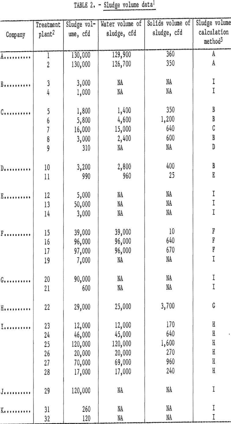
The sludge volumes presented in this study are not exact, because of the limitations encountered in data collection, but are of the correct magnitude. A total volume of approximately 1.1 MMcfd was produced by 30 of the 33 treatment plants. (Three plants did not supply enough data to allow direct sludge volume calculations.) Calculated sludge volumes ranged from 120 to 130,000 cfd among the treatment plants surveyed (table 2), resulting in an average of approximately 37,000 cfd per plant. The volumes were calculated from data provided by the treatment plants, using the calculation methods shown in the appendix. Several methods of calculation were necessary in order to compensate for missing data. Letters referencing the calculation methods used are listed in table 2 for each of the 30 treatment plants.
To provide a better understanding of the physical characteristics of AMD sludge, the sludge volumes given in the table have been separated into liquid and solid components. Not all treatment plants provided enough data for this breakdown. However, the 18 plants for which data were available produced a total of 837,000 cfd of sludge with water volumes of 823,000 cfd. The difference represents the actual solids volume of approximately 14,000 cfd. Per plant, this represents an average of almost 46,000 cfd of water and 780 cfd of solids. Thus, only about 1.7 pct of the total sludge volume handled was solids, and the remaining 98.3 pct was water.
For a graphic idea of the amount of sludge generated, imagine constructing a two-lane highway, 24 feet wide and 8 inches (0.67 foot) thick, using AMD sludge instead of concrete. If such a substitution were possible, the plants surveyed in this study alone would produce enough AMD sludge to construct 12 miles of two-lane highway every day, for a total of 4,380 miles in a year. The highway analogy can also give a clearer picture of the solids-to-water ratio of a typical mine sludge. Using the same cross-sectional dimensions, two highways are to be constructed, substituting sludge water for concrete in one highway and sludge solids in the other. Based on the averages given in the preceding paragraph, the “water highway” would extend 2,800 feet (one-half mile) and the “solids highway” would extend only 45 feet before exhausting the daily available road material of one treatment plant.
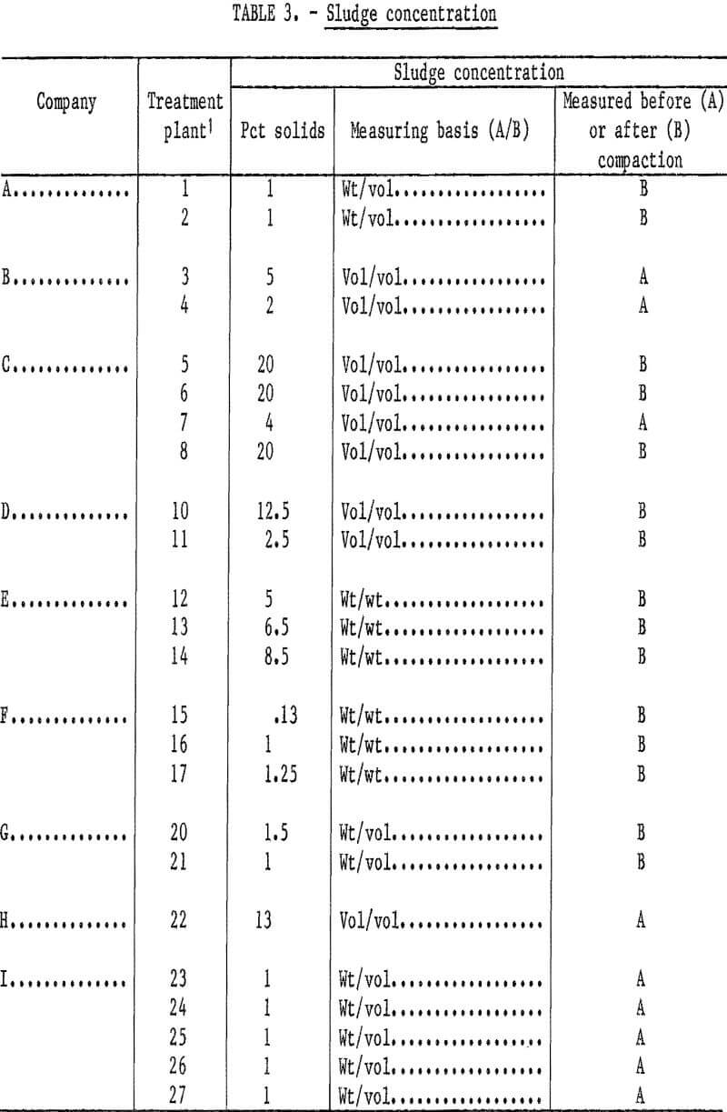
Because of the diversity of the information collected, methods of calculating sludge volumes also varied. Calculations were based only on yearly averages; however, it would take significant changes in the averaged solids content, which is the major factor in the sludge volumes generated, to change the order of magnitude of the volumes calculated in this report. Three different bases were used by the coal companies for measuring the AMD sludge solids concentration: (1) weight-to-volume, (2) weight-to-weight, and (3) volume-to-volume. In addition, sludge concentrations were measured either before or after compaction, as shown in table 3.
The inconsistency of available data necessitated certain assumptions to complete sludge volume calculations. The assumptions (percent solids of AMD sludge, weight-percent of treated mine water resulting as sludge, and specific gravity of iron hydroxide) were taken from a study conducted by Green International, Inc. They found a “normal range of solids in mine drainage sludge of 1 to 6 pct, with 2.5 pct being a good average value.” This figure is in agreement with our calculated sludge concentrations; only 7 of the 24 treatment facilities tested in table 3 fell outside of this 1- to 6-pct range.
Current Disposal Practices
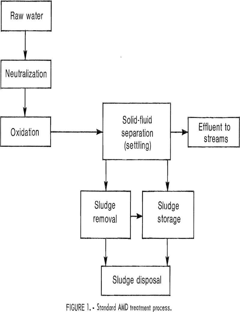
Sludge is one of the end products of AMD treatment. This study is primarily concerned with those steps of the treatment process succeeding the oxidation step (fig. 1) The observed sludge disposal practices involved three phases: (1) sludge settling and removal (2) sludge transportation, and (3) sludge disposal at selected sites.
Sludge Settling and Removal
The sludge disposal problem begins at the settling or solid-fluid separation stage of the AMD treatment process. Because of the physical properties of AMD sludge, clarifying-thickening and/or ponding operations are the two most economical and common methods of solid-fluid
separation. No other dewatering methods were observed.
Clarifiers are sedimentation basins or tanks where heavier particles in the treated mine water eventually settle to the bottom, ridding the effluent stream of suspended solids. Thickeners are also sedimentation vessels, but their primary purpose is to provide thickening of the suspended solids in treated mine waters. In several operations, flocculants were used in the thickeners. Thickening and clarifying occur simultaneously but independently, within the same unit. Therefore, to avoid confusion, the word “thickening” will be used to identify the thickening-clarifying operation.
Ponds, like thickeners, function as the initial solids settling unit. In addition, the sludge may be transferred from the primary settling pond and/or thickener to a secondary settling pond (polishing pond) used to further dewater the sludge, or to a permanent pond used as either a sludge storage or disposal area. An emergency pond is used when other ponds or thickeners are discharging polluted water or when maintenance becomes necessary.
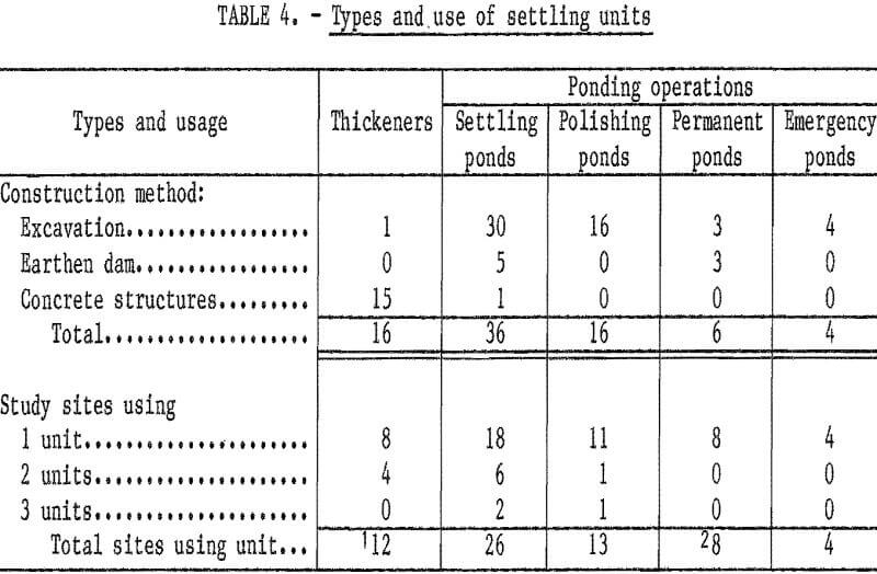
Table 4 gives a breakdown of the settling units surveyed. The construction of the units separates them into three categories: (1) excavations, (2) earthen dams, and (3) concrete structures. Once constructed, they were used for five distinct purposes: (1) thickeners (2) primary settling ponds, (3) secondary polishing ponds, (4) permanent ponds, and (5) emergency ponds. Ponds were popular among the coal companies surveyed, because of their inexpensive construction. Of the 78 settling units observed, 62 were ponds. These were generally simple excavations, although several were more elaborate earthen dams placed across large valleys and were designed to last the entire life of the mining operation without being emptied. All but one of the 16 observed thickeners were circular concrete rings, constructed above ground, with diameters ranging from about 70 to 110 feet and of varying depths. The exception was an earthen thickener.
Once solid-fluid separation has been accomplished, the sludge must be removed from the settling unit. In the thickener (fig. 2), the treated mine water is introduced near the center. As it loses its solids, it travels radially over a weir and out the effluent pipe to a stream. The settled solids are removed by two large, slowly rotating rakes that
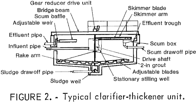
push the sludge toward the center sludge well. The sludge then enters the center sludge ports located near the bottom of the well and passes on through the pump suction line where it enters the sludge pump to be conveyed either to the final disposal site or to a further dewatering and storage area.
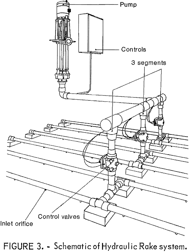
Two general methods of removal from ponds were observed—a suction method and a mechanical method. Sludge is sucked from ponds by the Hydraulic Rake Static Underflow System or by sludge pumps mounted on pontoons. The Hydraulic Rake system (fig. 3) draws sludge from the bottom of the pond through a network of pipes elevated about 4 to 8 inches above the pond floor. The network is partitioned into segments by control valves; each segment has a number of inlet orifices. The settled sludge covering the pipe network is drawn through the orifices into the system and out of the pond.
Pontoons draw sludge from the bottom of the pond with a hanging suction hose
connected to a sludge pump. Both the pontoon and hose traverse the pond by either mechanical or manual methods. A discharge hose, also connected to the sludge pump and other flotation devices, then carries the sludge from the pond.
Mechanical methods of sludge removal in ponds include the use of loading equipment (front-end loaders, bulldozers) and dredging. Removing sludge with loading equipment is a simple excavation process. Dredging a sludge pond involves the use of a dragline equipped with a clamshell bucket. The dragline scrapes the pond bottom and empties the sludge-filled bucket into trucks.
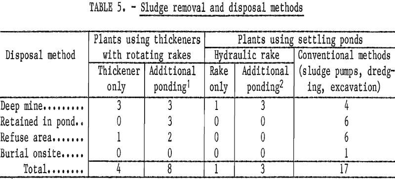
This study found 12 plants using thickeners 8 of these used some type of additional ponding. The Hydraulic Rake was used at 4 plants, and the three conventional methods (sludge pumps, dredging, and excavation) were employed by 17 plants. The sludge removal methods and the four disposal methods observed in this survey are shown in table 5.
Sludge Transportation
The AMD sludge was transported to its final disposal location by pipeline and/or truck. Where pipe was used, pumping distances ranged from 200 feet to 1 mile, and pipelines were buried because of climatic conditions. Trucks used to haul sludge were of various types and sizes. Including tank trucks, dump trucks designed with rubber seals on the tailgate, and conventional dump and pickup trucks that were simply sealed off around the tailgate. Sludge was transported by truck over distances ranging from about one-half to 3 miles.
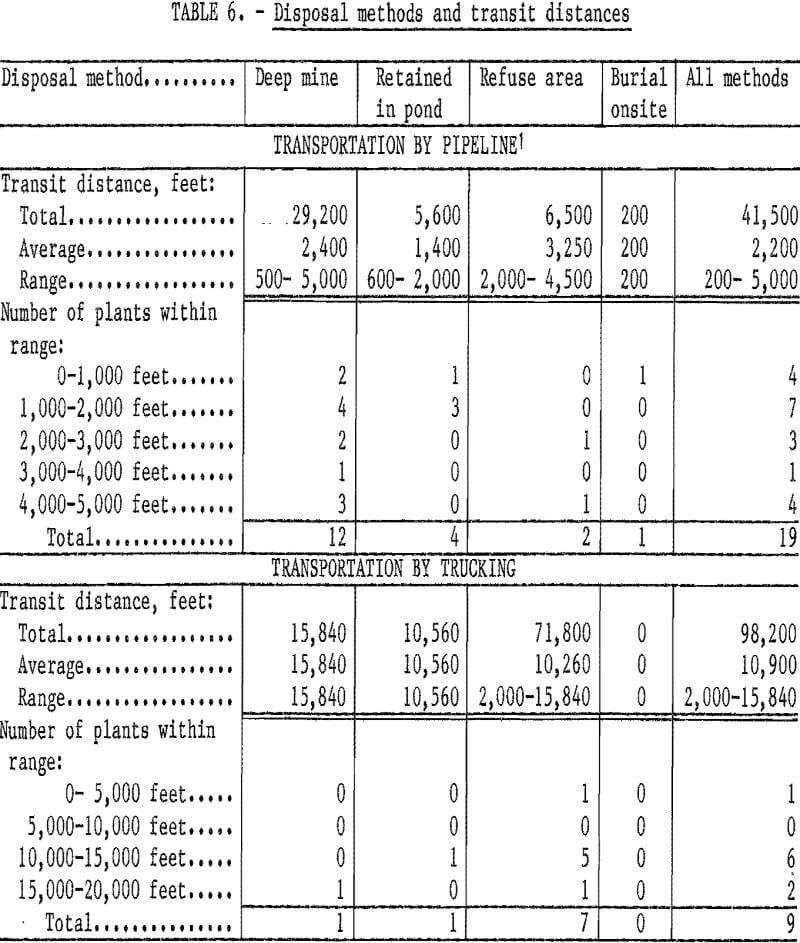
Transportation distances are largely-determined by the final sludge disposal method (fig. 4). Generally, sludge disposal sites were located a distance of 1,000 feet or more away from the sludge settling and/or storage sites (table 6). Of the 33 plants, only 4 reported that sludge was transported less than a
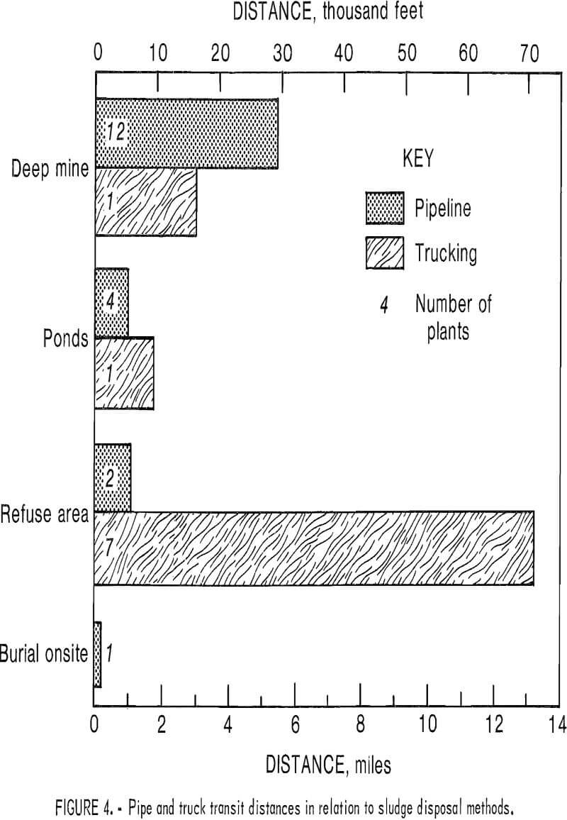
distance of 1,000 feet, and 5 plants did not supply distance data. Piping was the most common method of sludge transportation, with 24 plants using this method. Piping distances did not exceed 1 mile, the average distance being 0.4 mile. Nine plants used trucks to transport sludge to disposal sites. With one exception, all trucking distances exceeded 2 miles, with 2.3 miles being the average. Sludge transportation by truck was generally used to dispose of sludge on refuse piles and was generally contracted out to companies specializing in the service.
Sludge Disposal
Four sludge disposal methods were observed: (1) deep mine disposal, (2) permanent retention in pond, (3) haulage to and disposal at a coal refuse area, and (4) onsite burial. Only one company expected to use this last method. Changing disposal methods was found to be common practice. Seven of the eight coal companies that allowed visits to their treatment plants have had to change sludge disposal methods because of changes in water quality. In all seven cases, water quality changes resulted in increases in the sludge volumes being generated. (Water quality changes resulting in reduced sludge generation would not require changes in existing sludge disposal operations.)
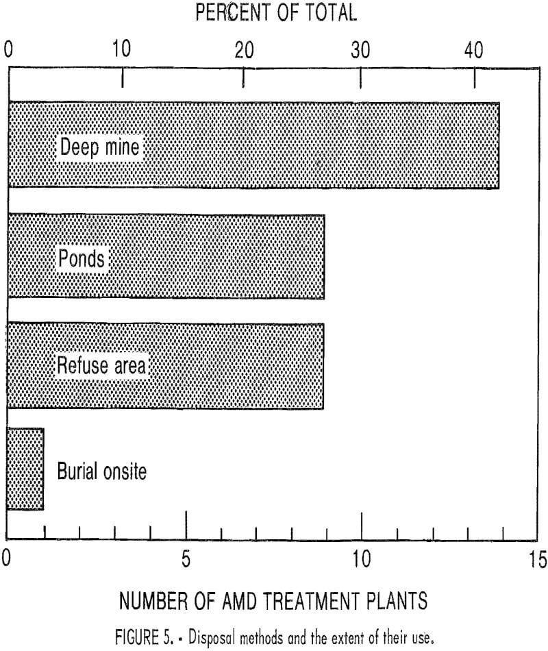
Deep mine disposal was the most widely used method encountered in this study (fig. 5), with sludge either pumped or trucked to boreholes drilled into underground abandoned deep mines or inactive portions of producing mines.
Ponds, in addition to serving as dewatering and storage areas, also served
as permanent sludge impoundment sites. The permanent impoundments varied in size, construction, and life of service. Size is usually determined by information obtained from exploration, laboratory tests, and general knowledge of the existing mining operations of the particular area. Therefore, depending upon estimated sludge production, pond construction ranges from simple excavation to earthen dams placed across hollows or valleys. A permanent sludge pond is usually designed to last the life of the mine. However, premature fill-up due to changes in mine conditions is not uncommon.
Another common method of disposal is to transport the sludge to a coal refuse area, A coal refuse area, for the purposes of this study, is defined as an old or new strip mine cut, or the refuse area of a coal preparation plant. This method usually involves trucking, but sludge may also be pumped to the refuse area via a permanent or temporary piping system. Shallow sludge ponds are constructed in the refuse area by dumping refuse in a large circle and forming barriers to retain the sludge. Once a shallow layer of sludge is placed in the pond, refuse is layered over the sludge.
Burial onsite is the least used disposal method. As previously mentioned, only one company reported an intent to use this particular method, which simply involves placing AMD sludge into a pond or excavation and covering it with earthen materials while it is still wet.
Assessment of Present Technology
Current practices for sludge settling, removal, transportation, and disposal described above were evaluated in terms of one or more of the following: maintenance, functions, effectiveness, cost, and both short-and long-range effects on the environment.
Sludge Settling and Removal
The chief factors in the choice between the two basic sludge settling units, thickeners and ponds, are economics and land availability. Based on the cost of excavation, construction, and maintenance, thickeners are assumed to be more expensive than ponds that have no earthen dams (76 pct of the ponds in the study), even though thickeners require less land. However, rising land costs may soon do away with the economic advantage that ponding has over thickeners, especially since thickeners can be placed in more varied topographic locations than ponds.
Sludge storage capacity becomes an important factor in evaluating the two types of settling units. All observed thickeners employ continuous sludge removal mechanisms or rotating rakes and have very little sludge storage capacity. Storage is an apparent problem when maintenance of the continuous sludge removal system becomes necessary. Raw water storage in underground sumps or surface ponds is necessary to avoid accidental discharges when sludge storage is inadequate. Raw water storage areas were reported to have storage capacities of from 1 to 7 days. A secondary sludge line, for discharging sludge to another disposal site or temporary storage area (emergency pond), prevents accidental discharge during maintenance operations.
Of the four emergency ponds reported (table 4), three were designed for use with continuous sludge removal systems; the fourth was associated with ponding systems.
Environmentally, thickeners are preferable to ponds for two major reasons: (1) better water-handling ability and (2) easier surface reclamation. During periods of extended influx of water, thickeners can control accidental discharges of polluted water much better than ponds can; the thickener drawoff pipe (fig. 2) allows safe discharge of the sludge to another site. The polluted water is pumped to a pond (8 of the 12 plants using thickeners employ ponds for one function or another) or to an underground disposal site (7 of the 12 plants with thickeners use underground disposal).
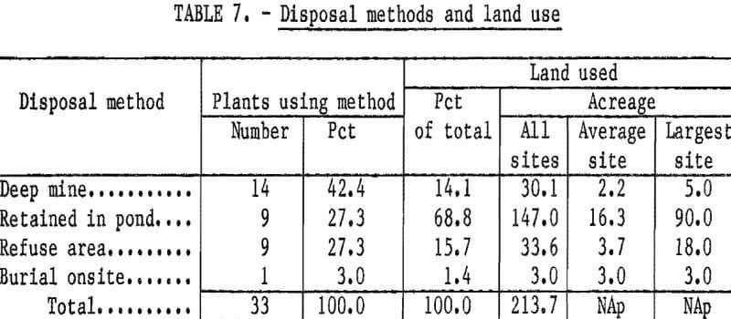
Finally, surface reclamation of the thickening unit and area is insignificant compared with that of ponds. As shown in table 7, those nine treatment plants using permanent sludge ponds or the retained-in-pond sludge disposal technique consumed approximately 70 pct (150 acres) of the total acreage covered in the study. More than a decade after the passage of regulations requiring mine operators to control AMD, we are becoming aware of the amount of land needed for. sludge storage and disposal. For very large ponds, the main problem is how long it will take a pond full of sludge to dry out, so that the material can be covered over with landfill. In the past, designers of permanent ponds have not been concerned with the length of time needed for ponds to dry out and were unaware that it could take decades.
Two types of failures may cause thickener operations to become ineffective. The first involves the thickening process. A thickening bed is on the bottom of the thickening unit and, as the sludge subsides, the bottom thickens. Consequently, as the sludge bed deepens, the underflow will generally thicken, all things being equal (that is, water quality, percent solids, influent flow). However, because of the hydrated character of AMD sludge, solids concentrations from conventional thickeners (and ponds) normally fall within a 1- to 6-pct range. Only 7 of the 24 plants providing this information exceeded 6 pct (table 3). Modified thickening processes exist, but 30 pct is the maximum solids concentration obtainable. As deeper sludge beds are used to obtain maximum solids concentrations, greater retention may introduce solids into the overflow, thus causing the thickener to fail.
The second failure may occur in “free settling” when new feed with a higher specific gravity plunges through the supernatant liquid, which has a lower specific gravity, and spreads out in a layer above the thickening solids. The new solids then settle into the “thickening zone,” and the remaining supernatant liquid, devoid of solids, travels up to the overflow as new feed is continued. However, when the area provided to settle out the solids from the feed layer is insufficient, a layer of liquid containing a certain amount of solids builds up from the thickening zone to the top of the thickener, causing excess solids to enter the overflow; the thickener is said to fail in “free settling.”
Ponding fails when sludge has built up so much that not enough time is available for all the insolubles to precipitate out of the treated mine water. The use of multiple ponds is the most environmentally advantageous method of ponding. When the first pond is so full of sludge that there is no longer sufficient retention time in the pond for settling to occur, the flow can be switched to a second pond, allowing further liquid-solid separation. Ponds also fail because of the thixotropic properties of the AMD sludge. Rippling action caused by wind can result in resuspension of solids in the supernatant waters, especially around the pond perimeter. Pond failure then occurs as the supernatant water, no longer devoid of solids, is discharged into the receiving stream.
The advantages of the two types of settling units are summarized below:
Thickeners
- Minimal land use
- Environmentally desirable
- Versatility
- No wind disturbance
- Small restorational area
Ponds
- Sludge storage capacity
- Low maintenance cost
- Low operational cost
- Low capital cost
The disadvantages are as follows:
Thickeners
- High capital cost
- High maintenance cost
- No sludge storage
- Requires raw water storage
- Fails in thickening
- Fails in free settling
- Eddy currents from rakes
- High operational costs
Ponds
- Wind disturbance
- Extensive land use
- Large restorational area
- Less control over accidental discharges
- Insufficient retention
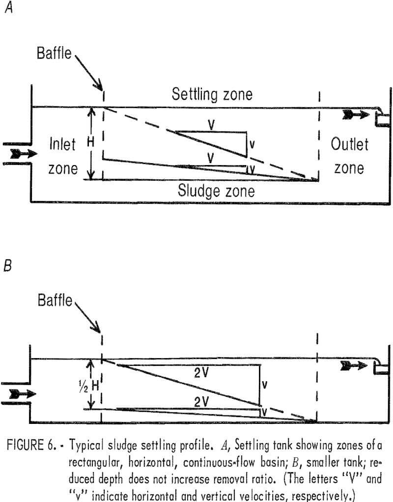
In addition to comparing the two basic sludge settling units, it is also important to evaluate the various methods of removing sludge from these units. Of the four observed sludge removal techniques associated with ponds, the Hydraulic Rake system has several advantages. Only four Hydraulic Rake systems were reported; no thickeners were observed or reported to use the Hydraulic Rake method. The installation of plastic pipe with inlet orifices on 2- or 3-foot centers has maintenance and operational advantages over the mechanical rotating rake found in thickeners. A proportioned suction pattern over the settling basin can be regulated to conform to the distribution of the settling sludge on the pond bottom. Longer pumping times at the influent end and shorter pumping at the effluent end are standard practice for a rectangular, horizontal, continuous-flow sedimentation basin (fig. 6). The system can be automated through the use of time controls. The AMD sludge has thixotropic properties, and resuspension of settled solids by the eddy currents of the rotating rake can adversely affect effluent quality. The Hydraulic Rake system has no adverse stirring action.
However, although the Hydraulic Rake system apparently costs less than the mechanical rakes of the continuous sludge removal system, it is generally more expensive than conventional sludge removal systems using pontoon sludge pumps, dredging, and loading equipment. Also, the Hydraulic Rake system cannot be used with mine waters having high sulfate concentration, because the resulting gypsum would block the valves and inlet orifices of the suction system. Maintenance was reported to be of major concern with the Hydraulic Rake. Apparently, air leaks affecting the compressor and problems with valves produced the most difficulty. Another difficulty with the Hydraulic Rake develops when excess lime is used in AMD treatment: The resulting sludge tends to “stand” or become gellike and lose some of its flow characteristics. Consequently, only the sludge in the immediate area of the pipe orifice is drawn out of the pond, resulting in a “rathole” (fig. 7). Once ratholing has begun, very little sludge is drawn out of the pond, and only water with low solids concentrations is removed. Maintaining a 1- to 2-foot layer of sludge over the piping network has been suggested, but
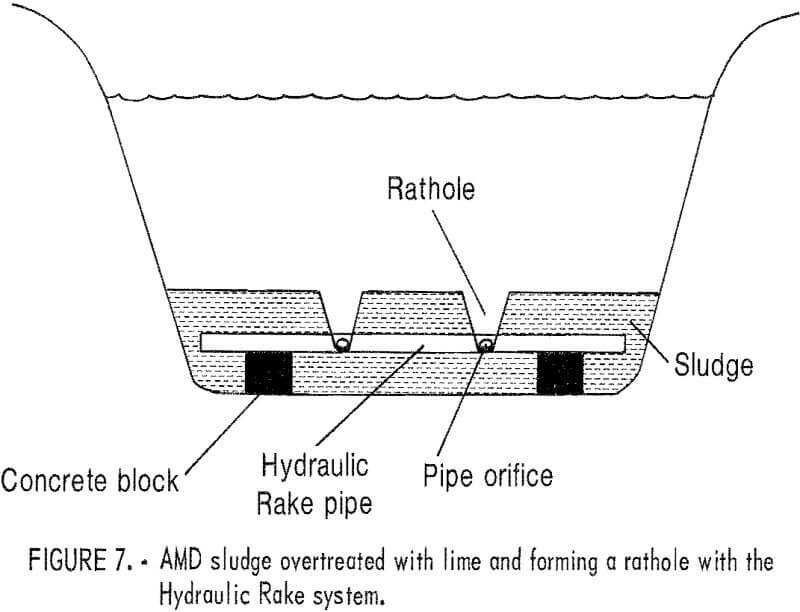
lime usage must also be monitored. The use of earthen basins with the Hydraulic Rake is much less expensive than the use of concrete basins; however, problems associated with earthen basins detract from the appeal of lower cost. Although the piping system can be supported on concrete blocks, concrete footers and steel supports are required for influent and effluent devices. Problems increase with uneven basin floors, wet weather, and basin sealing of the earthen excavations.
The conventional method of sludge removal, using pontoon sludge pumps, is one of the least expensive methods. The pontoons traverse the sludge pond either by mechanical or manual means, both of which require labor and power. This method differs from the rakes of the thickener and the piping of the Hydraulic Rake system in that the sludge settling unit need not be taken out of service because of breakdowns in the removal system. The equipment can be repaired easily on the pontoon itself or by replacing the sludge pump, with minimal expense or downtime. Removal can be either temporary or permanent, and a certain degree of automation has been applied to this type of operation. Sludge lines are easily accessible for cleaning or replacement. The simple fact that pontooning keeps sludge ponds in service during maintenance makes this sludge removal technique environmentally desirable.
Dredging is also a common method of sludge removal, but it is costly. Dragging the pond bottom with a clamshell bucket attached to a dragline is usually contracted out to private companies. One dredging company provided approximate costs of $2 to $4.50 per cubic yard for sludge removal. The average sludge production of the 33 treatment plants surveyed was 1,139 yd³/day.
Sludge removal by heavy loading equipment is the least used method. This method would work well except that the sludge is rarely allowed sufficient time to dry out. A common practice is to use two ponds alternately for sludge storage and dewatering; while one pond is in use, the other pond is drying. Because of the high water content of AMD sludge and the climatic conditions in the study area, sufficient drying to allow loading rarely occurs. Densification of sludge can be aided by (1) heating, (2) adding fly ash or some other type of absorbent material, (3) mechanical dewatering, and (4) keeping sludge in a windy location for maximum evaporation.
In table 8, the available sludge removal techniques are rated for storage capacity, economics, maintenance, and versatility. Temporary sludge storage in settling areas can be of major concern during maintenance and/or construction operations. Therefore, the sludge removal technique, employed whether it is a continuous or periodic operation, directly affects the “storage capacity” within the sludge settling unit. The “economics” of the various sludge removal techniques were rated on estimated initial and operational costs. “Maintenance” is the care required to keep the sludge removal system operating; this rating was based on field observations and discussions with treatment plant operators. The “versatility” of a removal technique was rated on its ability to be used with various other settling units (that is, ponds, thickeners).

Sludge Transportation
Pipelines and trucks were the two methods of sludge transportation used by the operators in this study. The sludge generated by existing treatment systems is an expensive commodity to transport, considering the distance, equipment, and maintenance involved. The haulage distances and resulting fuel costs are major factors of sludge transportation by truck, as are the purchase price and maintenance costs of haulage trucks and loading equipment. The high capital investment often forces the mining companies to contract pond cleaning and sludge transporting services, or to install piping systems.
Equipment required for pipeline transportation includes pumps, pipe, and pipe fittings. Based on the overall average of 0.4 mile (2,112 feet) of pipeline per plant, the approximate costs of pipe and fittings for the 4-, 6-, and 8-inch sizes are $3,000, $5,800, and $10,000, respectively. Note that these prices do not include elbows, labor, excavation, pumps, or design costs. Mainly, 8-inch pipe was used. Pumps and their sizes varied from site to site, as some plants required large pumps to lift the sludge to relatively high elevations while other plants used gravity flow.
Pipe maintenance is a major area of concern in sludge transportation. Gypsum buildup is the major contributor to pipeline clogging. The rate at which buildup in sludge lines occurs depends upon the water quality. Clogged pipelines were especially critical to those plants using thickeners with relatively limited raw water storage capacities. Based on prices obtained from several local pipeline cleaning companies, an approximate price range for the cleaning of AMD sludge line is $0.60 to $3 per foot, with an average cost of $1.50 per foot. These prices do not include the excavation costs of the ditches and ponds required by the State to collect the sludge at the points where pipe connections must be broken during the cleaning process. Based on an average pipeline distance of 2,112 feet, the cleaning of pipelines on a regular basis is costly. More details on sludge transportation distances for each disposal method are provided in table 6.
Increasing the flow rate is one method of reducing the frequency of pipe cleaning, since the sludge velocity in the pipeline controls the rate of settling and scaling. Velocities in the range of 5 to 7 fps cause a scouring action, which keeps the pipe cleaner. Although the hydraulic efficiency may drop owing to the increased velocity, overall operational costs should be less because of lower maintenance costs.
Sludge Disposal
In evaluating sludge disposal alternatives from an environmental point of view, deep mine disposal appears to be the best of the current disposal techniques. The AMD sludge is alkaline. Therefore, when deposited in an acidic environment such as an abandoned mine, it provides some neutralization. Iron hydroxide in the sludge does not readily go back into solution, so that it simply accumulates in the abandoned workings. The remaining clear water filters into the local hydrological system. Other environmental advantages of this method are the minimal surface area requiring reclamation once water treatment operations have ceased, and the fact that the difficulty associated with reclamation is minimal compared with that of the other disposal methods. From an engineering-point of view, this disposal method was found to be the only one that could be automated.
Unfortunately, deep mine disposal is not a panacea for the problems of AMD sludge. Surface access to an underground disposal site may be prohibited, owing to unavailability of access routes. Topography may be such that pipeline installation and pumping are not economically feasible. In addition, bulkheads used to retain the sludge can fail, causing flooding of adjoining active workings. A similar hazard exists when sludge is deposited in an abandoned adjacent mine, located in the same coal seam with a dip toward the active mine or in another coal seam above the active mine. In either case, the treated water can seep into the active mine workings, where it would become polluted again and require retreatment. The induced inundation resulting from this disposal method would severely inhibit future mining operations. Thus, the eventual environmental implications of deep mine disposal of AMD sludge are not yet clear.
The only advantage of the retained-in-pond disposal method is that no sludge transportation is required. There are several disadvantages. Large surface areas are affected and reclamation of the sludge ponds is difficult. Sludge drying takes years in the humid, temperate climate of Pennsylvania and West Virginia. The ponds remain exposed for many years and can be covered with fill material only when drying is complete. The ponds seldom are designed to meet realistic requirements and fill up prematurely. Often, the quality of mine water changes, resulting in increased sludge production.
When this happens, additional capital investment and disposal sites are required for the increased sludge volumes. The rippling of a pond surface by the wind affects the quality of effluent being discharged to the natural streams. The AMD sludge is thixotropic, and the rippling action, especially around the pond circumference, resuspends solids that are discharged in the effluent. Permanent retaining ponds built by damming a valley mouth are the most environmentally hazardous. Dam construction is presently regulated by Government authorities, but if a dam should fail, miles of natural streams would be quickly devastated.
The third disposal method, hauling to a refuse area, has several advantages. Since the refuse area is already an environmentally disturbed area, its further use for disposal simply Increases its efficiency, and the alkaline sludge helps neutralize seepage. Moreover, this particular disposal method has a built-in environmental safeguard. The existing runoff collection system of a refuse area collects all polluted waters, so that any pollution resulting from the sludge is collected and recycled through the treatment process.
The main disadvantage of sludge disposal in a refuse area is the long haulage distances involved. Of the nine plants employing this disposal method, seven used trucks for sludge transportation (table 6). Cumulative hauling mileage by these 7 plants exceeded the combined transportation distances of the other 26 plants. Given a pond with a half-million-cubic-foot capacity, full of sludge, and a 1,000-gal tank truck, 500 trips would be required to empty the pond. The average hauling distance is approximately 2 miles one way; consequently, a total of 2,000 miles would be traveled to empty one pond once.
Conclusions
Of the 33 treatment plants surveyed 6 treated water from abandoned workings; 7 treated water from mines scheduled to close within the next 5 years; 4 treated water from mines scheduled to close within 5 to 10 years; 7 treated water from mines scheduled to close within 10 to 20 years, and 9 treated water from mines scheduled to close sometime after that. Since mines continue to produce acid drainage as long as the raw materials are present, the drainage from abandoned mine workings continues to pollute thousands of miles of streams in the Eastern United States. Unfortunately, no method exists at present to stop this flow. However, State and Federal regulations require currently active mines to treat their drainage after closure. The number of mine drainage treatment facilities producing sludge will therefore increase in the future, resulting in a significant increase in annual sludge volumes and a scarcity of sludge disposal sites as coal extraction continues.
The major environmental and economic concerns resulting from the present methods of treatment of polluted mine waters are (1) the enormous volumes of sludge being generated, (2) limited sludge disposal sites, and (3) future implications of present disposal practices. The annual production of sludge in the United States indicates the magnitude of the problem. Moreover, present environmental laws that mandate treatment of polluted mine waters as long as the pollution exists insure continued growth in both AMD sludge production and disposal problems. Without an aggressive and directed effort at sludge volume reduction, sludge disposal will become extremely costly and environmentally unmanageable.
It is evident that the amount of AMD that is treated must be reduced so that sludge disposal problems can be alleviated. Better water-handling procedures, to prevent acidification of mine waters, must be developed and universally applied. Where an irreducible volume of water must be treated, treatment should be such as to provide a dense, easily handled, and readily disposable sludge.
The logical disposal site for such a sludge is the area from which it originated, abandoned mine workings. Three major benefits would result from underground disposal of a dense sludge; (1) Filling mine voids with solid material would reduce subsidence; (2) the alkaline sludge would assist in the neutralization of any acid ground water generated in adjacent strata; and (3) surface land consumption would be less than it is with the present disposal practices.
