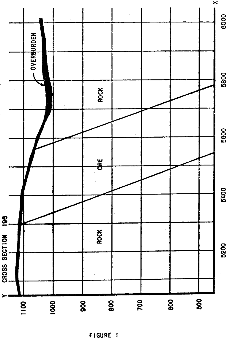
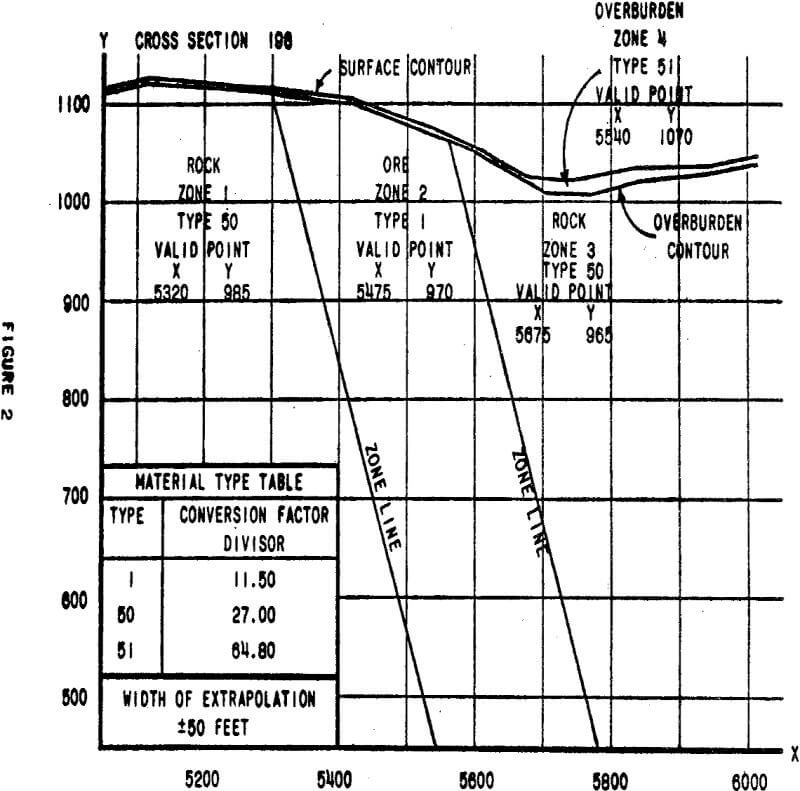
In the development of the ultimate pit limits for a narrow ore body, parameters necessary in the design of a functional, or working, pit become highly sensitive factors in the determination of ore reserve levels and their associated waste to ore stripping ratios. Through the use of geologic cross sections, ore reserves can be roughly calculated by utilizing a straight line approximation for pit wall slopes.
Cross Section Input Data
The bulk of the input data is generated in defining the topographical and geological aspects of the section. Once generated, it will not be necessary to alter this data unless the interpretation of the section changes.
Both the contours of the topographic relief and overburden-bedrock contact must be defined by a series of straight line segments approximating the contours. The (X, Y) coordinates of successive segment end points are entered as input data. In this program the topographical relief contour is referred to as the surface contour, and the overburden-bedrock contact is called the overburden contour.
- Zone Number – A reference number used to identify the zone in program output.
- Material Type – A cross reference number to a table of material types.
- Valid Zone Point – The (X, Y) coordinates for any valid point within the zone must be included in the input.
Optimization Mathematics
A. Consider the units associated with the numerator term of the stripping ratio as units of W. In the example W is in units of cubic yards or rock.
B. Consider the units associated with the denominator term of the stripping ratio as units of T. In the example T is in units of tons of crude ore.
C. STRIPPING RATIO = W/T = SR.
D. For the current best pit floor location the subscript B will be used.
E. For the trial pit floor location the subscript T will be used.
Currently the best design has WB, TB, and SRB associated with it. A trial design is made with results WT, TT, and SRT.
The differentials, or increments, between the two designs are calculated below.
- ΔW = WT – WB
- ΔT – TT – TB
- ΔSR – ΔW/ΔT
ΔSR, referred to as the incremental stripping ratio, is the key variable in the optimization of the cross-section design.
One parameter entered for the optimization of the cross section is the incremental stripping ratio limit, SRLIM. This limit specifies the maximum acceptable incremental ratio of waste to ore which can be mined profitably.
Inequality represents the introduction of the SRLIM constraint upon equation.
SRLIM ≥ ΔW/ΔT
This quotient form of the constraint inequality is inconvenient for evaluation purposes, so the inequality is restated in the following form.
ΔT – ΔW/SRLIM ≥ 0
Optimization Utilization
The incremental stripping ratio limit, SRLIM, discussed previously is in a sense related to the economics which would exist towards the end of the mine life. This limit states that in order to take the next mineable area of ore, ΔT, it is necessary to remove ΔW units of waste material to release this ore. The factor which complicates the use of a soundly based economic selection of SRLIM is that many of the ΔW units are on benches at a elevation higher than the position of the ore to be released, ΔT. These units of waste can possibly he profitably removed during earlier years of the mine life.
If the pit wall parameters are speculative, and only extensive rock mechanics work or actual mine development will dictate functional wall parameters, other curves can be developed for alternative sets of mining parameters.
Optimization Example
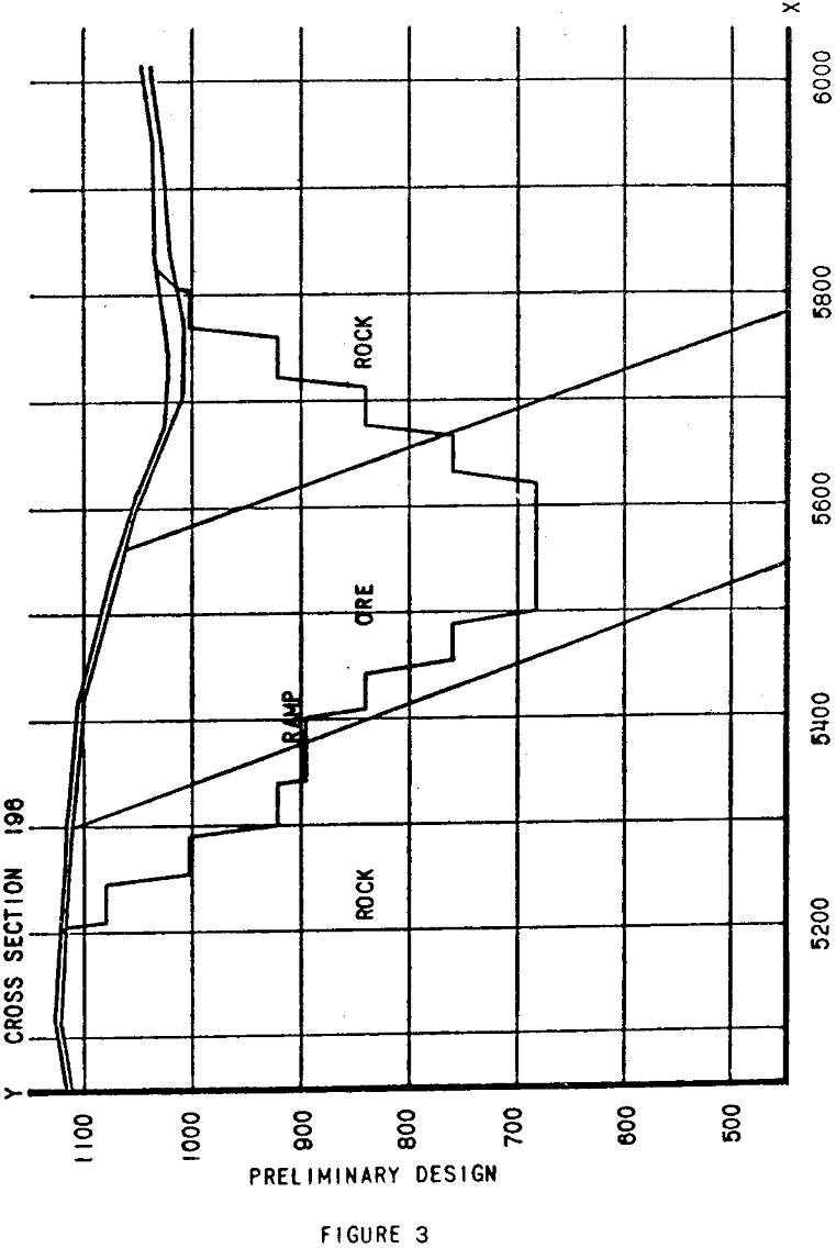
The cross section discussed previously will be subjected to optimization analysis for example. In all cases it will be assumed that the ramp at elevation 896 on the left wall will be necessary in the pit design. It is also assumed that mining of the ore body has not begun, so that the decision still has to be made as to the elevation of berms on each wall. Minimum width for the pit floor is specified as 80 feet.
For the example cross section, the pit floor was optimized in the floating mode at elevation 480 and a width of 80 feet. Since each cross section in the mine plan Is optimized independently, the possibility of developing a workable pit floor profile without manual analysis is quite remote. A plot of optimum pit floor elevation versus cross-section position in the pit will be useful in determining a working pit floor profile. An example of such a plot is indicated in figure 10 for a pit segment of ten successive cross sections.
Utilizing the plot of optimist floating mode floor elevation, end the berm elevation scheme developed, a functional pit floor profile is developed to minimize the deviation from the optimum profile.
To compare the performance of the optimization program against the preliminary example design, it is assumed that an incremental stripping ratio limit of 0.8 is acceptable and that it is necessary to constrain the elevation of the pit floor to elevation 680.
Optimization moved the toe of the left wall 25 feet to the left, and the toe of the right wall 15 feet to the left. The increase of 28,438 tons of crude ore for 9446 cubic yards of stripping results in an incremental stripping ratio of 0.33 which is a very favorable change in light of the limiting 0.8 ratio.


