Table of Contents
- Shell Liners
- End Liners
- Why the Aerofall Mill is Unique in the Comminution Field
- Details
- Pebble Mills Using Composite Pebble and Ball Charges
- All-Pebble Mill Plant with Single Stage Grinding
- Economic Application of Pebble Mills in the North American Economy
- Basic New Principles Incorporated in the Aerofall Mill
- Aerofall Mill Application
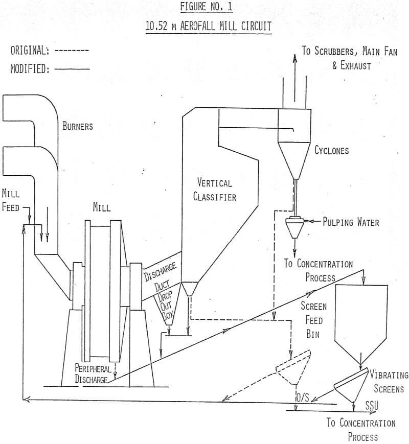
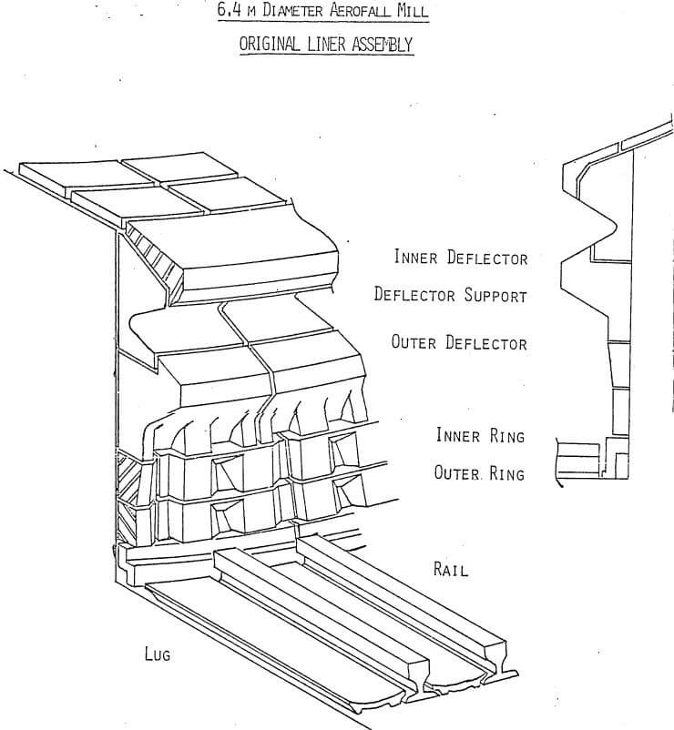
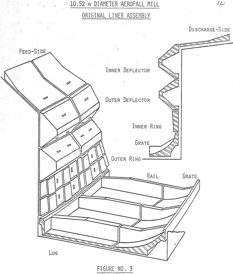
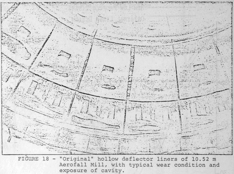
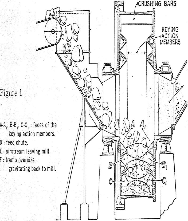
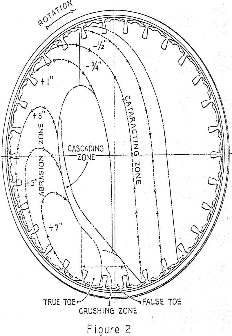
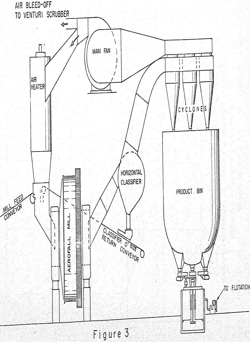
According to the manufacturer, a distinctive feature of the Aerofall mill, as compared to the conventional mill, is the special feature of its wedge shape “deflector” liner design (Figures 2 and 3) which was claimed to provide “keying” action in the mill that produces an important part of the crushing and grinding action in the mill.
Based on this, it would seem unwise to change the design of the liners, particularly the two rows of deflector liners. However, through detailed monitoring of the 10.52 m mills over an extended period of time, the following two key features were noted which led us to believe that the function of the wedge shape deflector liners might not be as critical as claimed and that there was room for improvement and raising the mill throughput:
- For a given charge level in the mill, as the liners wear, the mill will draw more power. This was particularly significant in the case of deflector liners. The mill drew a power of 2900 KW at full load with newly installed deflector liners, and increased to 3700 KW after the liners were worn out, the mid point being 3300 KW. With the harder ore presently treated, it was calculated that the mills should draw more than 3500 KW to reach the design capacity.
- As the power drawn by the mill increased, the grinding rates generally improved at the same time.
A liner study program was launched to examine both the end liners and shell liners with the following objectives:
- The new liners must provide more operating volume to pull the necessary power.
- They should provide sufficient lift to the ore to do impact grinding as well as exposing the fines to the air stream for removal from the mill.
- Maintain reasonable pressure drop across the mill so that there is sufficient air to handle the mill product.
Initial testing was confined to the 10.52 m mills only. Mill No. 10 was designated as the test mill, and its results were compared against the other 10.52 m mill, No. 9. Throughout the test period, Mill No. 9 retained the conventional Aerofall mill liners. Both the shell and end liners were evaluated for different profiles with different “lift” height and at different parts of the mill. Normally, only one change was made at a time so that the impact of each design change could be properly evaluated.
Shell Liners
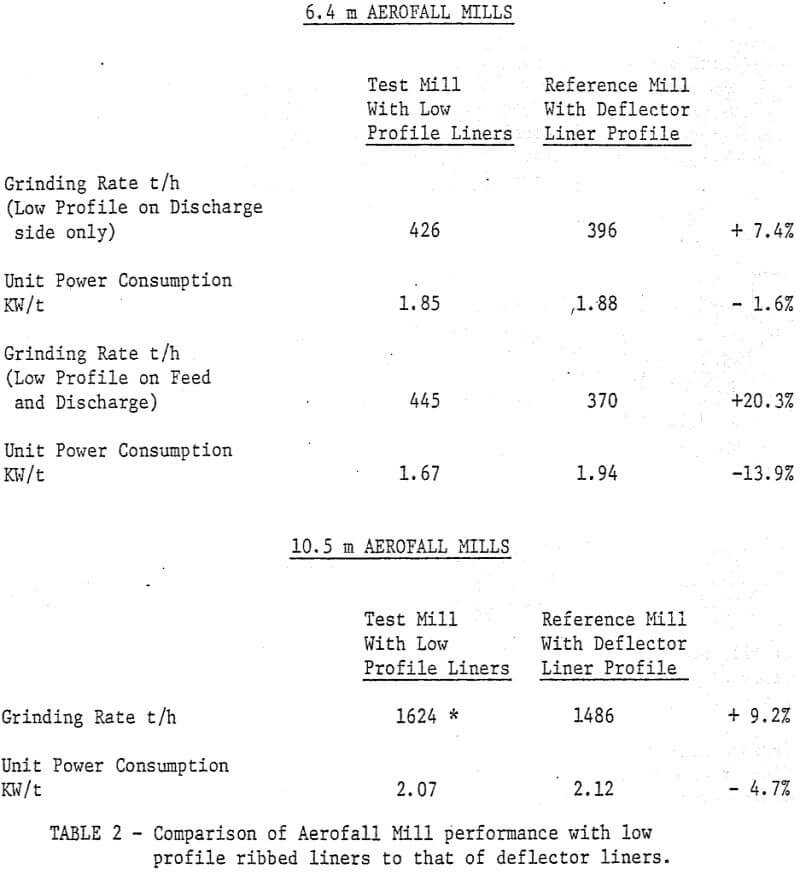
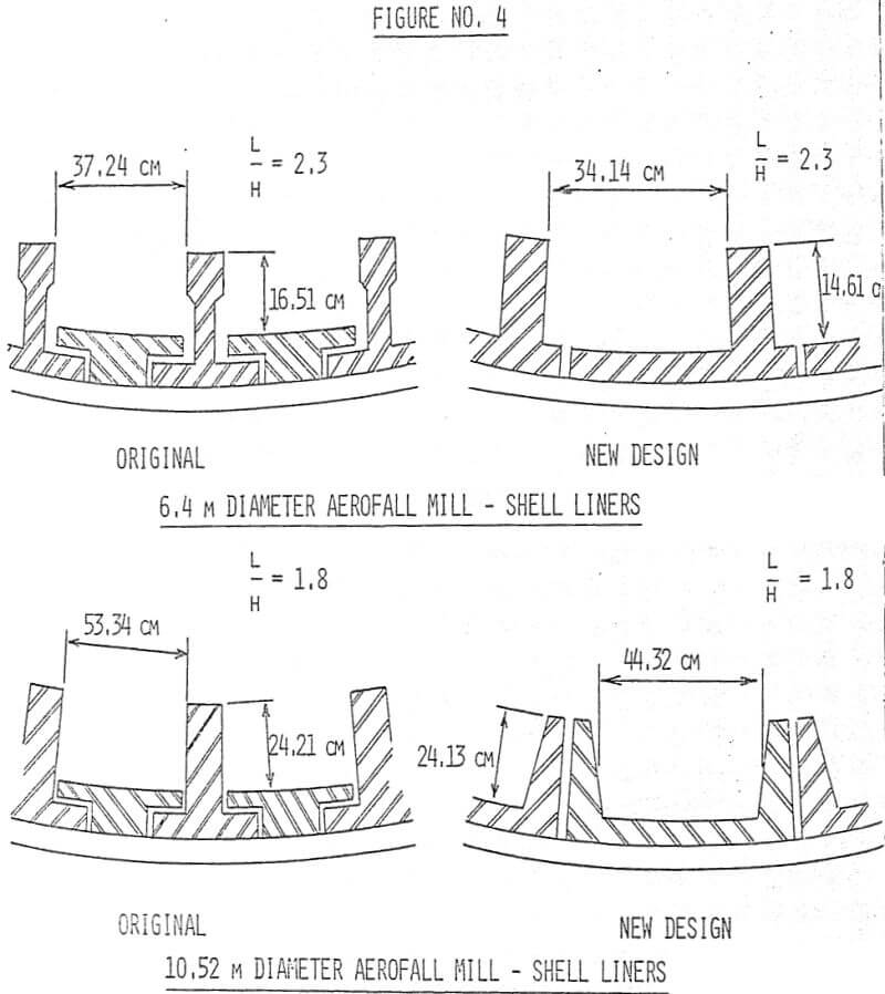
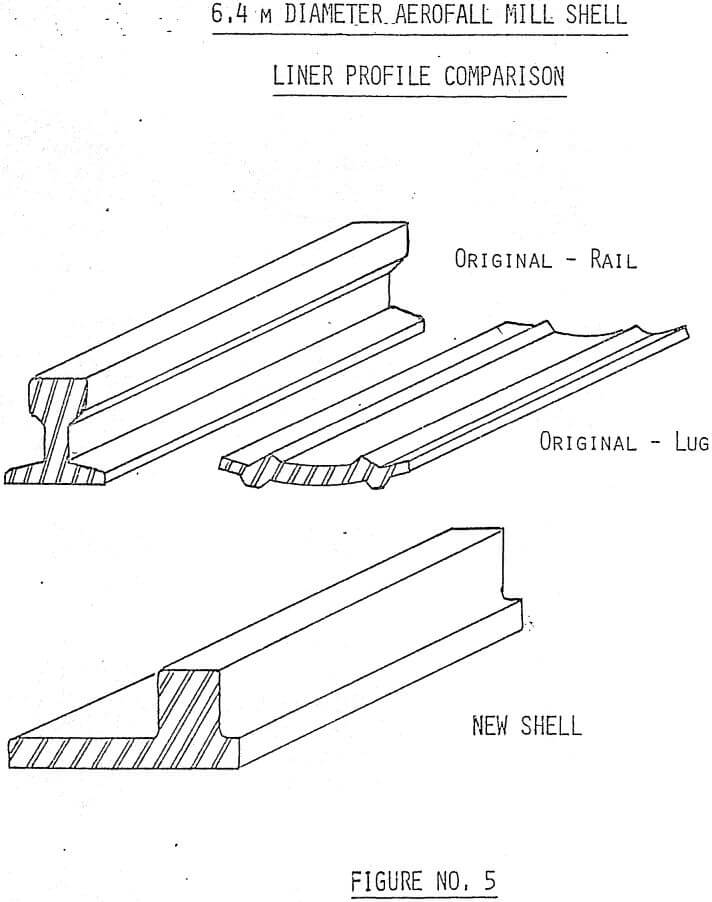
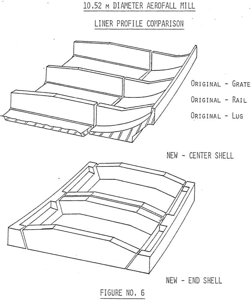
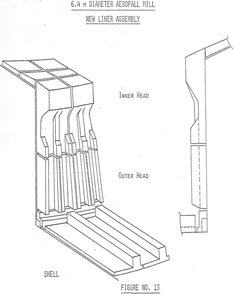
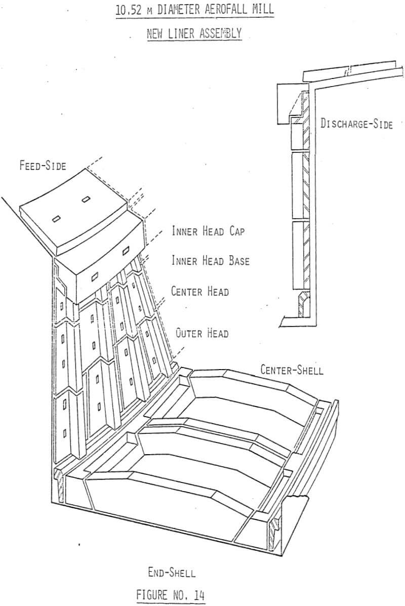
Our study confirmed that there exists an optimum range of lifter spacing to height ratio in autogenous mills. In our operation the ratio that gave the best production was in the range of 2.5 to 5.0, which was also in line with their findings. To illustrate the significance of the ratio on mill power draft and thus the mill throughput, our study showed that by maintaining the same lifter spacing while increasing the lifter height from 29.21 cm to 36.83 cm in the 10.52 m mill (the spacing to height ratio reduced from 1.8 to 1.4) caused the power draft to drop by 18% with a corresponding decrease in grinding rate. Since the lifter spacing to height ratio in the original design was in the proper range, the new design adopted the same ratio, which in the 6.4 m mills is 2.3 when the liner is newly installed, with replacement after the ratio is increased to about 5.5. In the case of 10.52 m mills, the ratio is 1.8 with new liners and about 5.5 at replacement (Figure 4). However, to simplify the maintenance work and reduce the scrap losses, the casting design was changed from the original separate rails and lugs to a version for both the 6.4 m and 10.52 m mills where the lifter bars are an integral part of the shell liners, as shown in Figures 5 and 6. Additionally, due to the length of the 10.52 m mills, the new liner incorporated a three piece design (Figure 6). The center section which bears most of the wear is replaced more frequently than the two end pieces.
End Liners
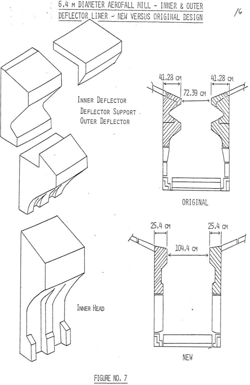
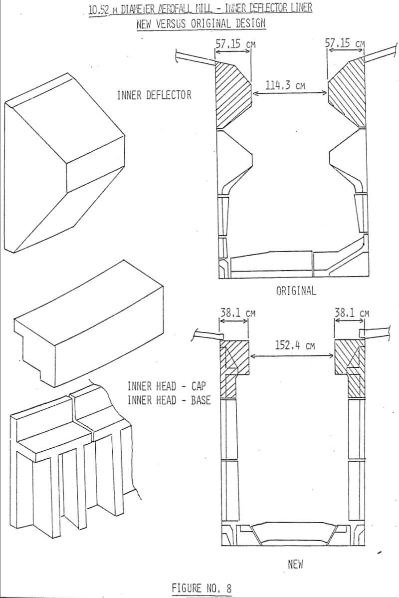
The study showed that since the deflector liners (Figures 2 and 3) represent the most significant portion of the mill volume displaced by the liners, they have the most significant effect on mill power drawn.
Inner Deflector Liners
The inner deflector liners on both ends of the mill restrict the width of the ore curtain and have a direct effect on the pressure drop across the mill. An initial increase in the distance between the inner deflector liners on feed and discharge sides of the mill improved mill performance. However, a further reduction in the liner thickness (a larger increase in this distance) resulted in an excessively high pressure drop, adversely affecting the product removal from the mill. Under the latter condition, not only was the grinding rate reduced despite higher mill power drawn, but liner wear was also accelerated on the discharge side of the mill due to fines build-up and racing against these liners.
Outer Deflector and Ring Liners
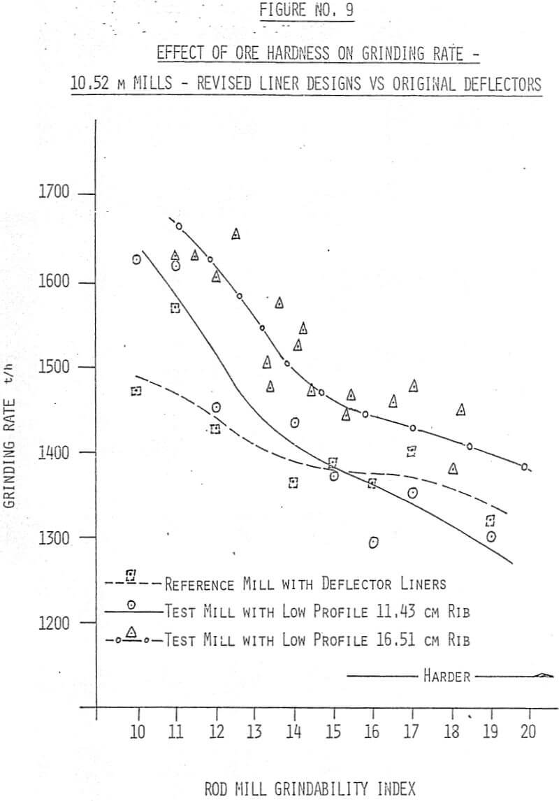
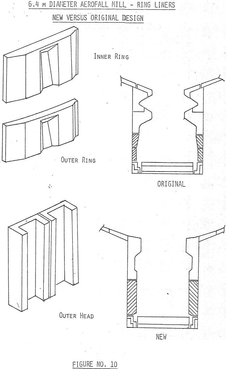
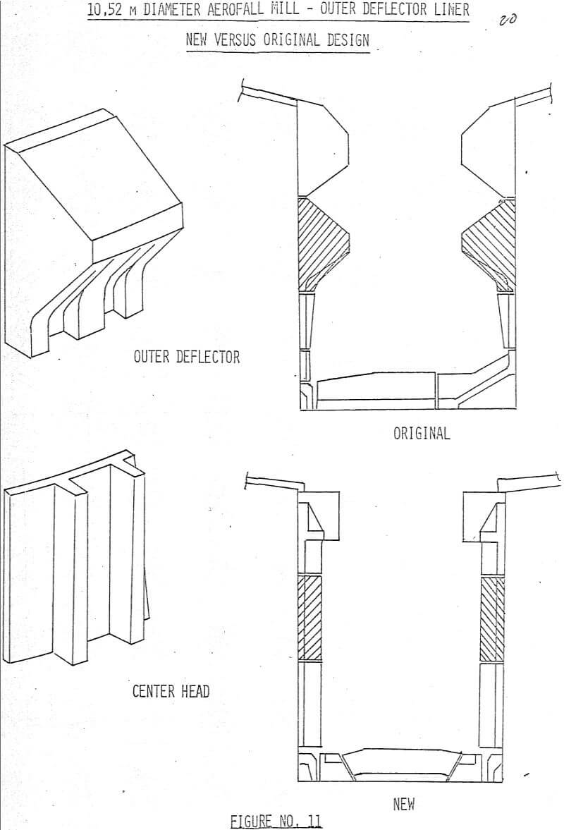
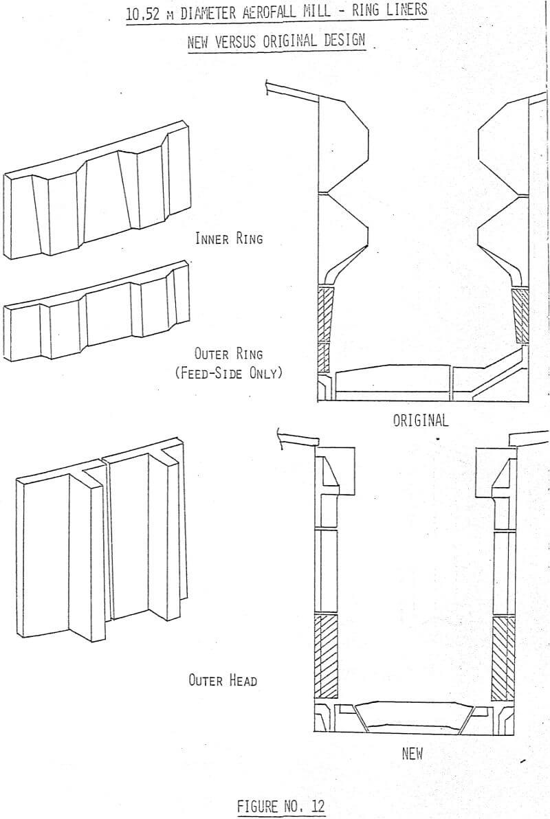
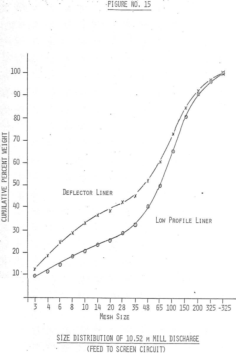
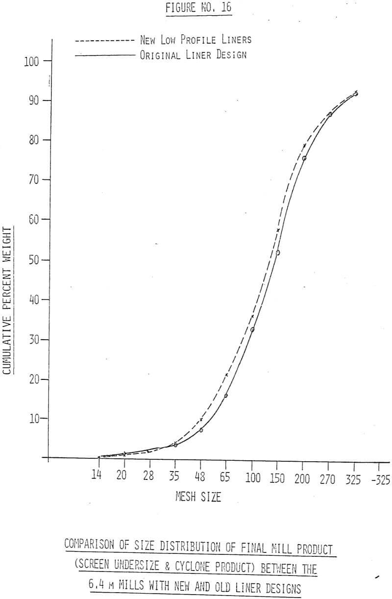
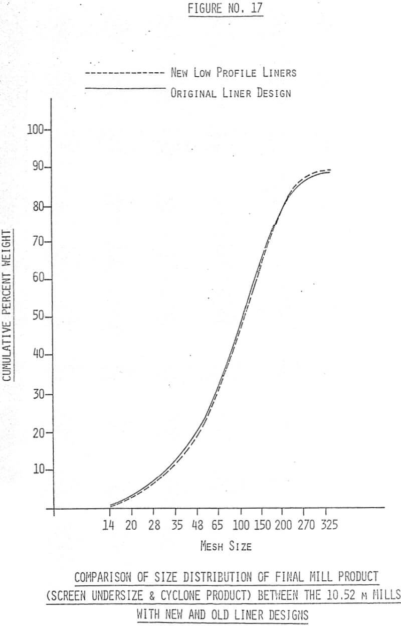
Our observations indicated that the outer deflector liners had the most significant effect on mill power draft. They also played an important role in the grinding performance of the mill. Replacing the outer deflector liners by low profile liners will allow the 10.52 m mill to draw in excess of 4000 KW. However, with only the smooth plate liners, the grinding efficiency was very poor in that there was insufficient overall lifting action to generate the impact grinding action and to expose the “ground” material to the air stream for removal from the mill, an action which might have been provided by the deflector liners. It was found that radial ribs must be incorporated into the end liners and extended downward to the two rows of ring liners. The height of the ribs was found to be critical to the grinding efficiency of the mills. With a rib height of 5.08 cm in the 10.52 m mill, there was insufficient overall lifting action. As a result, not only the grinding rate was low at less than 1320 tonne per hour, but there was excessive attrition grinding that produced fines and severe wear on the liners on the discharge side from ore racing against them. At 11.43 cm rib height, the test mill outperformed the mill with conventional full deflector liners with softer ore, but did not perform as well on harder ore. By increasing the rib height to 16.51 cm, the mill not only drew the required power but also consistently outperformed the mill with the original full deflector liners (Figure 9). We subsequently found the rib height required for the 6.4 m mill to be 10.16 cm.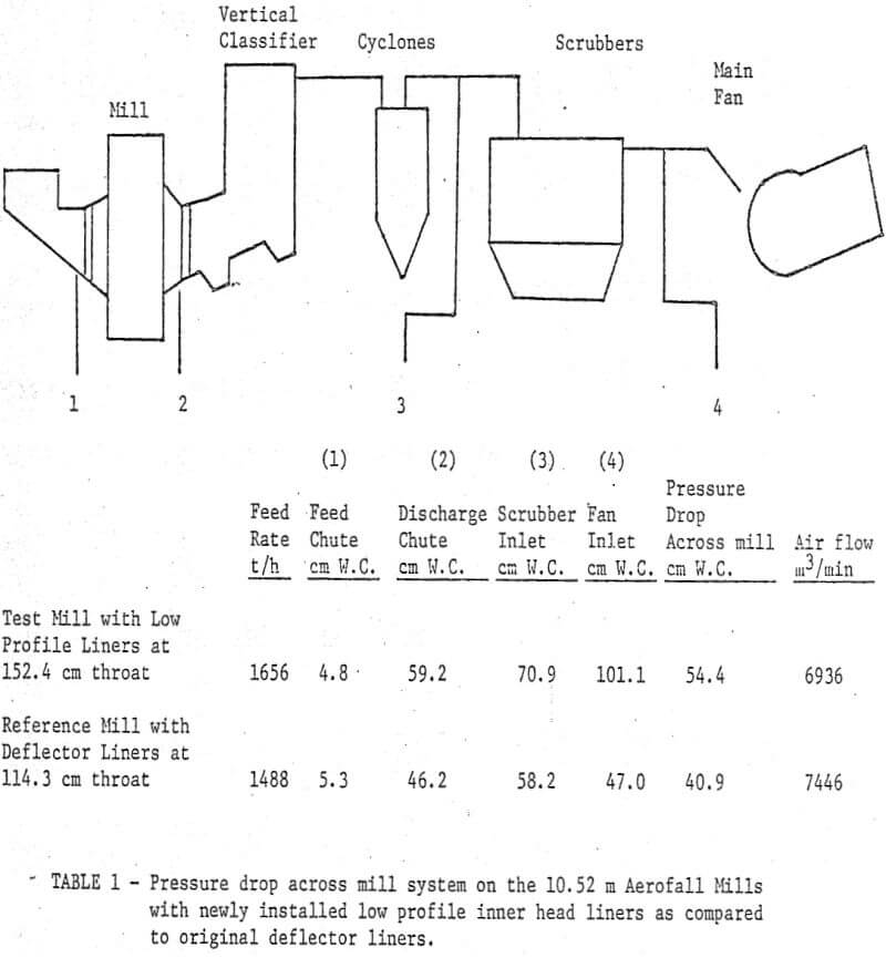
Why the Aerofall Mill is Unique in the Comminution Field
During recent years there has been a great deal of confusion in the North American mining industry with the introduction of new comminution terminology and claims (without substantiative evidence), for various types of equipment in this field. The authors will attempt to clarify the terminology used, and where possible, give illustrations of plant practice with actual operational and pilot plant data. This is considered necessary in order to obtain a clear picture of the comparison of such equipment to the revolutionary change that the Aerofall Mill has brought to the mining industry.
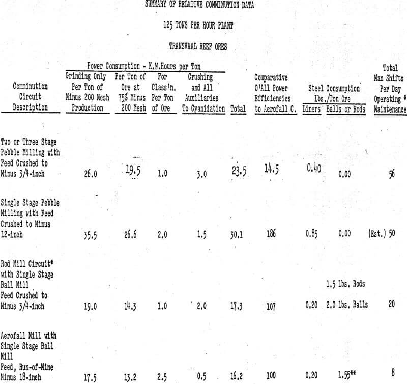
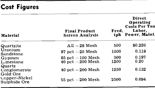
An Aerofall Circuit as compared to either a Crusher-Rod Mill Circuit or Pebble Mill Circuit may show a reduction in total operating costs in excess of 50%.
Details
The term “Autogenous” as now in general-use, basically applies to wet “Pebble Milling Practice.” This form of comminution has been in use in South African gold mines for some 50 years and has reached its highest state of development in that country. Primarily, the only recent changes that have taken place are in mechanical perfection and the size of the units. There have been no new fundamental concepts. To fully understand the economics of this type of comminution as compared to a Crusher-Rod Mill Circuit or an Aerofall Circuit for use in the North American economy, the authors will review it’s application in South African practice, where there is a sufficiently long history to arrive at reasonable conclusions.
The “Pebble Mill” grinds by the same mechanism, and conforms to the same established laws as a Ball Mill. Basic differences, affecting capacity and grinding efficiency, may be summarized as follows:
(a) The Pebble Mill, using ore as grinding media, will have a charge of lower specific gravity than that given by steel balls. For example, with a pebble charge having a specific gravity of 3.0 compared to steel balls having a specific gravity of 7.6, all other factors being equal, a Ball Mill of the same size and volumetric loading as the Pebble Mill will have, theoretically, 7.6/3.0 or 2.53 times the capacity.
However all other factors are not equal. For the most efficient reduction of the ore, the size of the grinding media is of extreme importance. For instance, feeding a minus ¾-inch feed to a Primary Pebble Mill requires a 6-inch pebble to effectively reduce it, while in a Ball Mill the same size feed can be effectively reduced with a 3½-inch diameter ball. Further, pulp viscosity hinders grinding to a higher degree with pebbles than with balls; in order to partially offset this factor. Pebble Mills must be operated at a lower pulp density than Ball Mills.
Pebble Mills Using Composite Pebble and Ball Charges
The historical use of adding steel balls to Pebble Mills is two-fold.
The first was to increase capacity of existing plants without any additional capital expenditure. The second application was made to plants where, due to narrow mining widths, insufficient coarse ore was available to meet the pebble demands of the grinding units.
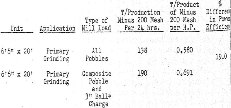
The percentage of balls to pebbles used varies from 12% to a maximum of 33%.
The increase in power input to the mills is 5% to 15%.
The average increase in capacity is 10% to 25%.
Ball wear varies from 0.8 pounds to 2.0 pounds per ton of ore milled.
The ball wear factor of 2.0 pounds per ton at 33% of the total charge is appreciably higher proportionately than an all steel ball charge, showing the effect of abnormally high steel consumption in using partial coarse feed. (The pebbles.)
The average South African all-Pebble Mill Plant treating approximately 125 tons per hour, in its pebble preparation and ore handling uses in excess of 5,000 feet of conveyors. A portion of this system is used in sorting waste. Each Primary Mill has two bins, one feeding ore and one feeding pebbles. Each Secondary Mill has a pebble storage bin with its individual feeding arrangement. For this comparatively small tonnage rate the plant would use a minimum of three 8′ x 16′ Primary Pebble Mills followed by six 8′ x 16′ Secondary Pebble Mills. The flowsheet would therefore consist of twelve separate bins with twelve separate feeding systems.
The Aerofall Circuit would consist of the Primary Crusher, eliminating all secondary and tertiary crushers with their closed circuit screens, drawing from an open stockpile eliminating bin storage, and feeding to a single Aerofall Mill, followed by a single Ball Mill. The plant would use only three conveyors, one from the Primary Crusher to the stockpile, a shuttle conveyor over the stockpile, and a feed conveyor from the stockpile to the Aerofall. This latter conveyor rarely exceeds 250 feet in length. Total operating and maintenance man shifts per day would be a maximum of eight.
All-Pebble Mill Plant with Single Stage Grinding
The following is the description of a plant treating approximately 125 tons per hour. Ore from the Mine is dumped into a large transfer bin. An elaborate conveyor system of 42″ and 36″ belts with a total length of 4,800 feet carries ore through grizzlying and washing plant prior to picking of waste. Undersize from the washing plant is classified in a 60″ spiral classifier with the overflow going direct to cyanidation, and the sands joining the main bulk of the ore. Oversize rocks are crushed to minus 12″ in a 36″ x 24″ jaw crusher.
Fine and coarse ore are fed from their respective bins on to a common conveyor which runs to each grinding unit. The rate of feed on to the belt is set manually through a drum type feeder. The feed belt to each mill is in turn controlled by what is described as the “Williamson Electronic Control,” a power sensing device which stops and starts the feed belt depending upon the power being drawn by the mill.
Economic Application of Pebble Mills in the North American Economy
Analysis of the Pebble Mill data would indicate that its major potential economic use in the North American economy is in tertiary grinding when sliming of the product is immaterial, rather than fine grinding with a minimum of sliming.
In current practice, generally, Ball Mills are being used (employing 1.0-inch to ¾-inch diameter steel balls as the charge replacement. These balls are expensive, averaging 12 cents per pound, and their effective grinding life is short.
Where the Aerofall Mill is used, tertiary and even secondary grinding would rarely be employed, as the mineral constituents of the ore are released at a much coarser grind than is possible with any other known type of comminution equipment.
Basic New Principles Incorporated in the Aerofall Mill
The theoretical concepts regarding the unique mode of operation of the Aerofall Mill has been described previously. That paper describes the interaction between the crushing bars and the keying action members which results in the formation of a keyed zone, under compression.
(There is a general misconception of the Aerofall Mill in that the major work is performed by free fall impact. The free fall zone is a placement zone only with material of less than one inch in size, free falling. Probably less than 2% of the useful work is performed in this zone.
From an operational point of view, the keying action reduces internal slippage of the charge to a minimum resulting in low liner and ball wear together with the ability of the mill to transmit high power loading with a high degree of efficiency. The following are examples:
The effect of varying the mill speed shows that the Aerofall Mill does not conform to any other type of rotating drum-type mill. Variation of speed varies the relation of impact to abrasive forces with marked change in the character of the mill products. At the higher speeds it will produce its maximum degree of fineness to mineral liberation, at the minimum power input; at lower speeds, coarser grinds are produced and power input increases by as much as 100%.

Comparison of an Aerofall Mill Circuit on a lead-zinc ore was carried out by the Eagle-Picher Mining & Smelting Company at their Central Mill, Cardin, Oklahoma. This is a case where the minerals are released at a comparatively coarse grind and little overall advantage could have been expected from using the Aerofall Mill over the plant’s installed equipment. It will be noted that even with the low head value, the combined decrease in milling costs together with increase in metal value recovery amounted to 82 cents per ton of ore.
Aerofall Mill Application
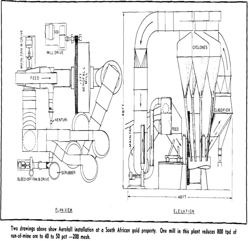
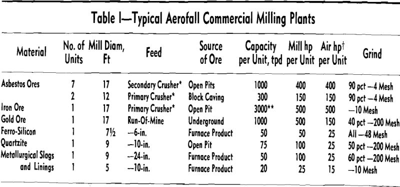
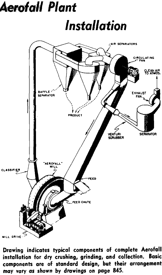
New large beneficiation plants have been using an almost standardized crushing and grinding flowsheet. Typically a primary gyratory is followed by several stages of fine crushing and grinding is often carried out in a rod mill operating ahead of one or more ball mills. The clearly labeled trend is to an increasing number of stages with a decreased reduction ratio per machine. Current Aerofall mill installations represent a complete reversal of this tren —one mill replaces the several stages of crushing and grinding a more conventional flowsheet would call for.
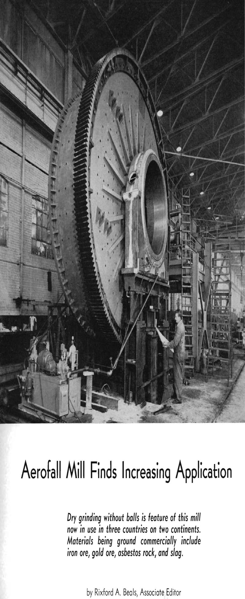
Changes in ore character and in moisture content have been problems in autogenous mill design. It is stated that the Aerofall mill can tolerate up to 4 pct moisture without effect upon capacity or product. With heating apparatus for the air intake, the mill has reportedly ground ore up to 12 pct moisture. Flexibility as to feed make-up is also supplied, if necessary, by adding a ball charge of up to 2.5 pct of total mill volume. With such a charge ball consumption figures range less than 0.05 lb per ton.
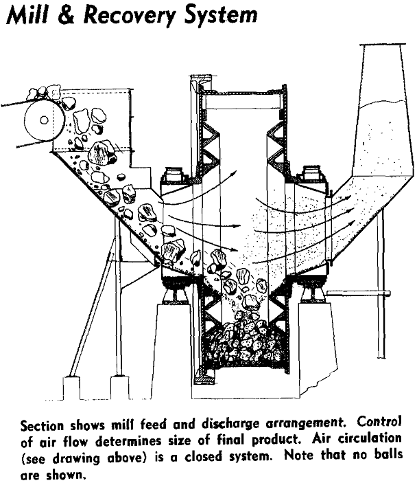
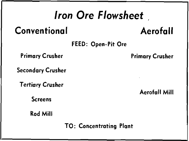
Aerofall mill development had its beginning in the late 1930’s. Despite the depression which was then almost at its worst, so far as the base metals industry was concerned, the management of Consolidated Mining & Smelting Co. of Canada started a comprehensive program of research for the purpose of testing various theories of comminution. The objective was to improve performance of the then existing mill equipment.
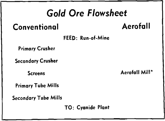
First commercial installation was at a gold mine in northern Canada. The plant operated only a very short time because it was found there was insufficient ore to maintain production. However, much valuable data was obtained so that correlation between the test and commercial units could be started.
