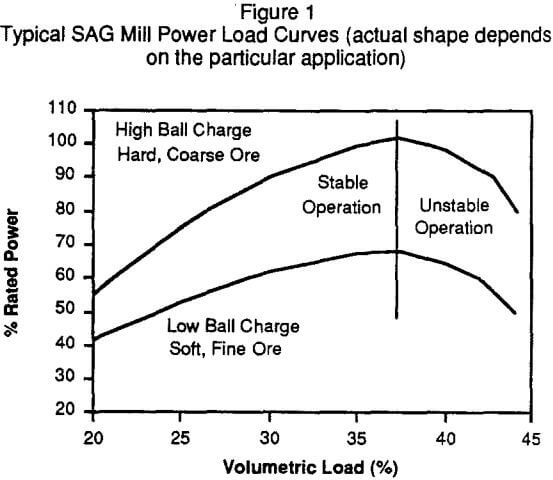
It is obviously well understood that autogenous AG and semi-autogenous SAG mills operate quite differently from conventional rod mill or ball mills. Since these mills are of a grate discharge type, they operate with varying loads, with the power drawn by the mill being dependent upon the volumetric load within the mill and factors that influence the viscosity of the charge, as shown in Figure 1.
Variables that effect load and charge viscosity include; particle size and shape, volumetric ball charge, ball size, mill pulp density, and the specific gravity of the ore. The condition of liners and grates may also have an effect on the shape of the power/load curve obtained.
At loadings above 35% to 37% of mill volume the power drops off as the load is increased. Operation in this area is unstable and the mill is referred to as being “overloaded”. Operating problems arise from the difficulty in recognizing this overload condition, as it can occur at varying power draws depending upon the characteristics of the ore being milled and other process variables.
Since no technique has been developed to date to directly monitor the SAG mill volumetric load, it is necessary to infer this from other measurements. Although various approaches have been employed, all rely to some extent on a direct or indirect measurement of the mill weight, i.e. the sum of the weights of the mill, liners, balls, water and rock. The most common method is to monitor the back pressure in the high pressure lubrication line feeding the mill trunnion bearings, with this pressure being a function of the load in the mill.
The traditional strain gauge type load cell has had limited success due to lack of ruggedness, finite life expectancy in applications with cyclical loads, and the high cost of replacing the unit due to extensive down time. More recently, Asea Brown Boveri have introduced a load cell which operates on the principle of a magnetoelastic effect on a susceptible piece of metal. It has no moving parts, and has been used extensively in steel rolling mill applications and recently under a large diameter SAG mill. Regardless of the instrument employed, the trend of the load signal in conjunction with the power signal trend can be used to determine the location of the mill on the power/load curve, and allow the operator or control system to make decisions as to adjustment of the feed rate.
Modeling SAG Mill Performance
Prior to embarking on the development of any type of high level control strategy, a series of tests is required to determine the nature of the relationships between SAG mill throughput, load (as measured by bearing pressure and measurements inside the mill) and power draw (amps and/or kilowatts). The objective is to develop preliminary cause and effect relationships that provide the foundation for a computer based control strategy for maximizing, or optimizing in the case of a fixed tonnage operation, SAG mill throughput.
Depending on the level and type of instrumentation installed, bearing back pressure can be recorded directly from pressure gauges mounted locally on the high pressure lubrication system, or from an appropriate analog or digital load signal in the control room or at an operator station.
In terms of monitoring power, one has to ensure that true SAG mill power is being recorded. For example with a variable speed DC drive, the AC power measured on the primary side of the rectifier transformer is the total power consumed by the silpac unit and DC drive as well as the power factor correction capacitors and reactors. Similarly, if one is monitoring motor amperage on a synchronous motor, it is important to also monitor voltage and power factor in order to correctly derive the power draw.
Prior to initiating the test work, the SAG mill should be ground out in order to determine the ball charge. To achieve an appropriate range for the variables of interest, throughput should be varied over a relatively wide range. For the high tonnage tests feed rates should be increased to meet or exceed the normally acceptable load on the SAG mill motor, or load in the mill, whichever has been identified as the primary constraint.
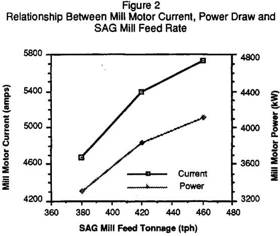
An example of the relationship between mill motor current, power draw and SAG mill feed rate is given in Figure 2. As expected, the load on the mill motor increases as the SAG mill feed rate increases. Although three data points are insufficient to fully define the relationship, the rate of change in both current and power, relative to feed rate, is lower at the higher tonnages. This indicates that for this set of tests the mill is operating on the left hand side of the power load curve.
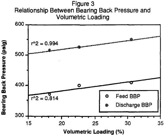
Each test involves stopping the mill, retracting the feed chute and measuring the charge volume (balls plus rocks). These values are then correlated with the feed and discharge end bearing back pressure (BBP) readings recorded while the mill is running, just prior to the shut down, as shown in Figure 3. The slopes of the two linear relationships are almost equivalent, indicating that both signals are equally sensitive to load changes.
To determine if a SAG mill is operating within the generally established guidelines for a large diameter to length ratio SAG mill, the mill performance can be modeled mathematically. A generalized SAG mill power draw equation developed by Austin, is given by:
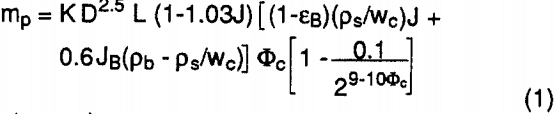
where the parameters used in the model are defined as:
mp= net mill power (kW)
K = a constant (kW/ton m0.5)
D = mill internal diameter (m)
L = mill length (m)
J = fractional volume of mill filled by total charge
εB = effective porosity of the total charge
ps = mean density of rock (tons/m³)
Pb = mean density of ball material (tons/m³)
wc = fractional solid content in the SAG mill
JB = fractional volume of mill filled by balls only
Φc = mill rotational speed as a fraction of critical speed