Table of Contents
Accidental firings of explosive initiators have occurred occasionally with some uncertain correlation to the pneumatic loading of ammonium nitrate-fuel oil (AN-FO) blasting agents. The exact association, if any, between these firings and static electricity is unknown. This report describes the role of pneumatic loaders in generation or transfer of static electricity and discusses the possible relationship between the use of such loaders and accidental firings of electric blasting caps (EBC).
Laboratory loaders simulating both blow case loaders and eductor loaders were investigated. The blow case loader forces a more or less continuous slug of prills through a loader tube at relatively low prill velocities. Eductor type loaders entrain prills and external air through aspirator, action. Eductor loaders, in the laboratory at least, consume more air per unit mass of prills loaded than do the blow case loaders.
Electrical capacitance, or capacity, is a property of all objects; the magnitude of the capacity is determined by the size, shape and composition of the body, its nearness to other objects, and other similar factors. When electrical charge appears on the body (capacitor), a voltage distribution also exists. It is common to consider the voltage to result from the presence of the charge. The charged electrical condenser has stored energy according to the formula H = ½ CV², where H = stored energy in joules, C = capacitance in microfarads (µf), and V = voltage in kilovolts (kv). Energies of 10 mj (0.01 joule) or more can be accumulated in pneumatic loader operation, unless special precautions are enforced. Energies of 10 mj can cause firing of electric bridgewire detonators and must be considered to be a hazard. The electrical currents, or stored capacitive energy, to be expected from operation of pneumatic loaders represent a hazard only to the explosive initiator system; they do not represent a hazard to the AN-FO explosive in the absence of the initiator.
Discussion and Description of the Problems
Firing of Electric Blasting Caps
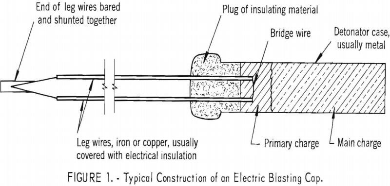
Construction of an electric blasting cap is shown in figure 1. An equivalent electrical circuit of the EBC and firing source are shown in figure 2. The only differences between 2A and 2B are that the current source in 2A is shown as a battery and in 2B it is shown as a condenser; either arrangement can fire the blasting cap. The schematic battery of figure 2A might actually be a battery, some type of shot-firing device, a hand-crank generator, or other similar device.
In normal firing, electric current passes through the resistive bridge-wire and heats it until the primary explosive is initiated. The primary explosive then initiates the main charge of the EBC. Normal firing currents for mining caps are 0.3 amp or more, although one pamphlet makes reference to 0.25 amp. Since the heat produced by an electric current is proportional to the square of the current, currents appreciably smaller than the minimum firing current cannot significantly affect the cap (reducing the current to one-half its initial value, reduces the heating to one-fourth its initial value). The maximum currents generated by pneumatic loaders are about 10 -5 amp, or less. If passed through the bridgewire at the rate generated by the loader, the electric current from the loader can produce only negligible heating and represents no hazard. If an electric charge is accumulated to
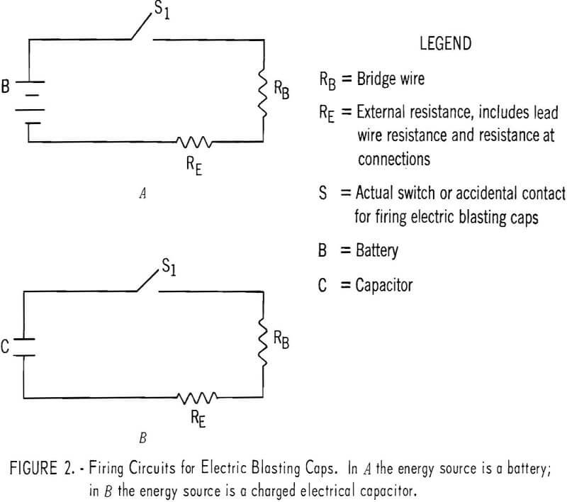
give a high voltage on a condenser, rather than flowing away as a small current, rapid discharge of the condenser through the bridgewire can fire the EBC. High voltage on the condenser causes very large currents through the small resistance of the bridgewire even though the currents persist only for time periods of a few microseconds, or less. Because of the very large currents, important heating can occur even though the discharge time is short.
It has been found that the discharge of 10 mj capacitive energy through the bridgewire is enough to fire an EBC.
Private conversations with representatives of manufacturers have indicated that even smaller energies will fire the cap if there is a break in the bridgewire such that spark discharge occurs within the primary charge. A representative energy for initiation by a discharge within the primary charge was quoted as 0.5 mj for commercial EBC. The data of Wyatt and coworkers show that even lower energies could apply to other types of electric detonators and initiators. It is important that continuity of the legwire-bridgewire-legwire circuit be assured before the EBC is installed. Continuity should be tested with a blasting galvanometer recommended for the particular type of cap being used. Continuity in the EBC circuit is assumed in the remainder of this report.
The usual EBC has a metal shell as indicated in figure 1. It is possible for an electric current to pass between the metal shell and some portion of the legwire-bridgewire-legwire circuit. Information about this mode of initiation is scanty. It is usually accepted that the steady current between shell and legwire required to fire the cap depends upon the past history of the cap the voltage and current to which it may previously have been subjected, etc.
Discharge of 30 mj capacitive energy has been reported to fire one type of blasting cap in shell-to-legwire discharge. It is emphasized that this 30 mj should be considered as a number typical of one manufacturing procedure. Other numbers, larger or smaller, may apply to other designs and it is advised that the user request this information from the manufacturer of the blasting caps.
Fortunately, the intrinsic capacitance of the metal detonator shell is very small being a few picofarads (pf or µµf) at most. A potential difference of 100 kv, or more, between shell and legwire would be required to store 30 mj energy. Actual dimensions and insulation resistances will not permit such voltage to exist across this capacitance in practical AN-FO pneumatic loader operation. However, if another, larger capacitance is connected in parallel with the shell to legwire capacitance, the required energy would become available at much lower voltages. A charged man holding the shell of a detonator whose legwires are grounded would be an example of such an additional parallel condenser.
Nature of Charging Source
The electrical current or voltage source of concern in this problem is the pneumatic air-operated machine used to load AN-FO in the borehole. As the prills travel through the loading tube, some contact between prills and tube walls must occur; some of the contacts result in electrical charge transfer thus leaving both prills and loading tube in an electrically charged condition. The charged prills are carried along with the uncharged prills in the loading tube and this charge transport is an electric current. In addition, the charges on the prills cause a voltage (potential) distribution within the loading tube. As a consequence of this voltage distribution current flows, in accordance with Ohm’s law, between the charged prills and the various objects which can absorb the charges: the tube walls, the storage hopper, etc. This latter current can only come from the charges on the prills; the existence of this current depletes the charges on the prills and influences the voltage distribution accordingly. (A more complete, mathematical description of the electrical field problem is given in the appendix.)
The fraction of contacts giving charge transfer is approximately fixed in any given apparatus. Experimentally observed currents have been 1-10 µamp (1 µamp = one-millionth ampere). The resistance through which this current flows may range from a few thousand ohms for quite damp AN to several million megohms for quite dry AN. The voltage required to cause this current to flow through such resistances ranges from a few millivolts for the low resistance to several million volts for the higher resistance.
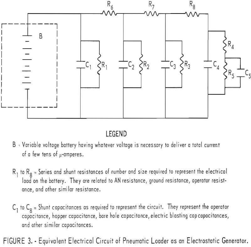
The pneumatic loader may be represented by the equivalent circuit of figure 3. The various resistances and the battery (generator) are interrelated in such fashion that the maximum current flow can be only a few micro-amperes. As noted above, the battery (generator) voltage may be a fraction of a volt or several million volts. The several capacitors may then be effectively uncharged or may be charged to quite high voltages.
Nature of Capacitors
Three properties of actual capacitors, or of combinations of ideal capacitors and resistors, are of importance: The magnitude of the capacitance, the series or discharge resistance, and the parallel or leakage resistance. The magnitude of the capacitance (C), determines the energy which can be stored on the condenser at given charging voltage, represented by
H = ½ CV²…………………………………………………………(1)
where H = stored energy in joules, C = capacitance in µf, and V = voltage in kv. The capacitance of an object may conveniently be considered to consist of two parts: The capacitance due to its shape and size and the capacitance due to its proximity to other objects and surfaces. The average human being will have a capacity of about 100 pf as a consequence of his size and shape. This capacity would have been measured with the man standing on an insulating stool and well removed from walls, etc. If the man is then permitted to step down on the floor and his capacity again measured, the capacity will be found to be typically 25 to 50 percent larger than when he was on the insulated stool. The increased capacitance is due to the closer proximity of the body, principally the feet, to the floor and the amount of the increase will depend to some extent upon the thickness of the shoe soles.
The relative capacity of the loader case can be estimated by comparison of its size to the human being. The loader, insulated from the ground, will have a capacity that is dependent upon the thickness of the insulation in the same fashion as for the man.
Laboratory measurements usually show the capacitance of the human being standing on the floor to be within the range of 100 to 200 pf with perhaps a few exceptional cases being as large as 300 pf. Capacitances as large as 600 pf have been reported for miners wearing boots and standing in pools of water. The increased capacity in this case arises from the same effects as does the increase in capacity in stepping from the insulated stool to the floor. A capacitance of 200 pf has a stored energy of 10 mj when charged to 10,000 volts.
The discharge resistance of a capacitance is the internal resistance through which the current must flow when the condenser is discharged. This resistance which is a small fraction of 1 ohm for metallic bodies is ordinarily between 1 and 1,000 ohms for the human body and may be many megohms for insulating bodies. If the series discharge resistance is large, the discharge current is proportionally small. Only objects comprised of good electrical conductors metals in the case of the hopper and salt water in the case of the human being-can be discharged with sufficient: rapidity to produce currents large enough to be hazardous to the detonator.
An actual condenser will not hold charge indefinitely as would the “ideal” condenser; the charge slowly leaks away through the leakage resistance. For the hopper case insulated from ground this leakage resistance would be the resistance of the insulation. For the human being, this leakage resistance would represent, primarily, the resistance of the footwear.
Time Constants
When a condenser discharges through a single resistor, the voltage across the condenser varies with time according to the relationship
V = Vo exp (-t/RC)………………………………………………………..(2)
where V = voltage at time t, Vo = voltage at t = 0, R is the resistance in megohms, C is the capacitance in µf. The product, RC, is known as the time constant of the resistance capacitance combination. After the discharge has proceeded for a time t = RC, the voltage across the condenser is about 1/2.79 the original voltage, after a time period t = 2RC, the voltage is 1/(2.79)² the original voltage, etc.
The RC time constant may be used to describe the time dependence of the possible hazard from charged condensers. Suppose that a condenser has been charged to 15 kv and that hazard from this condenser exists at 10 kv or more. One RC time constant after being disconnected from the charging source, the voltage has been reduced to approximately 6 kv by discharge through the leakage resistance and hazard no longer exists. Suppose the condenser of concern is a human operator having a capacitance of 200 pf. If the operator is wearing leather shoes, his RC time constant is about 0.02 second. Thus, the operator becomes discharged quite rapidly after he loses contact with the loading tube charging source. However, if the operator is wearing shoes or boots of high-quality synthetic rubber, his time constant is at least 200 seconds or more than 3 minutes. In this case, the operator may leave the loading tube and walk to a detonator and still retain sufficient voltage (energy, really) to fire the detonator.
The disappearance of free charge from within a volume of dielectric material is governed by
q = qo exp (-st/ke)……………………………………………………….(3)
where q is electric charge at time t, qo is electric charge when t is zero, s is volume resistivity of the material, k is dielectric permeability, and e is a constant whose value depends upon the set of units employed. This equation is of importance to a later discussion of electric charge in the borehole.
Significant Aspects of the Loader and Its Operator
The unique hazard to the explosive initiator in AN-FO loader operation is the possibility that one of the charged capacitors may be discharged through the EBC. Preventive procedures should be aimed either at reducing the energy on the various capacitors or at minimizing the mobility of the capacitors and of the initiator leads.
Over the range of experimental conditions covered by this investigation, and by that of Prugh and Rucker, the net effective rate of charge generation in a pneumatic loader is inherently limited by the rate at which charging contacts can occur. Theory indicates that the dielectric breakdown strength of air might become a limiting factor under extreme conditions of dryness but such conditions of dryness were not encountered by Prugh and Rucker nor achieved in this laboratory investigation. (See appendix.) The loader is then a current-limited electrical source. The output voltage of the source is the product of the current and the resistive load through which the current passes to ground.
The section on Experimental Methods and Results and the work of Prugh and Rucker show that the probability of an individual prill becoming charged is essentially independent of the loading rate; that is, the electric current is proportional to the mass loading rate and the total charge generation is proportional to the quantity loaded. Reduction of the loading rate can therefore be used as a method to reduce the output voltage of the pneumatic generator, but the technique has only limited utility.
In figure 3, if the current is 1 µamp and the electrical resistance of the loading tube, prill column, etc. is 10 11 ohms, then the maximum voltage which the loader can produce is 100,000 volts. It would be necessary to reduce the loading rate by at least a factor of 10 to reduce the maximum voltage to 10,000 volts. Conversely, if the maximum possible current is 10 µamp and the resistance of tube, column, etc. is 10 megohms, then the maximum possible voltage is 100 volts. The various intrinsic capacitances of the loader hopper, operator, etc. are such that no hazard exists at 100 volts; at 1,000 volts the hazards should ordinarily be negligible but acute hazard may exist at 10,000 volts.
Control of the output electrical resistance is a more desirable way of controlling the output voltage than is control of the prill loading rate. The most desirable elements in control of the output voltage level are a semi-conductive loading tube and grounding leads. Proper use of such a loading tube assures that the operator, hopper, and other externally connected capacitors do not become charged to hazardous levels because of low values of R4, R5, etc. (See fig. 3.) The use of a semiconductive loading tube does not entirely prevent the delivery of electrical charge to the borehole and this aspect is discussed later.
The effective resistance of the hose, column, etc. can also be limited by moistening the AN. Quite reasonable moisture contents reduce the effective resistance to acceptable levels. Certain difficulties do exist but the technique should be usable in almost all instances with a blow case loader and in some instances with an eductor loader.
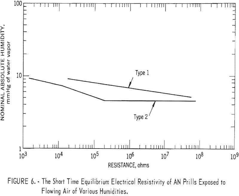
Figure 6 shows typical values of resistivity versus moisture content of air flowing through type 1 and type 2 AN samples. (See Experimental Methods and Results.) The operational problem is the control of moisture content of the transport air so that the prills are not dried by the transport air. The problem arises in the following fashion: If water-saturated air at 70° F is compressed to 10 atm (about 147 psig) in a tank at 70° F and is then expanded back to 1 atm, the expanded air will have a 70° F relative humidity of only 10 percent. Thus, the high-pressure air supplied for transport purposes can ordinarily be considered to be dry air and will produce drying effects such as are described in the appendix. To hold the AN-FO electrical resistance at an acceptably low level, the dry air should be mixed with wet air or otherwise moistened after expansion in order to have sufficient water content. The problem of mixing wet and dry air has been discussed by Prugh and Rucker in connection with the particular correlation of their investigation. Moisture contents such as are required to achieve an acceptable level of resistivity do not interfere with the firing of the AN-FO and may be less than that required to give the most sensitive explosive.
The addition of moisture to the AN reduces the surface hardness of the prill as well as reducing the electrical resistance. This reduction in surface hardness tends to cause the formation of a film of AN on the interior of the loading tube and thus further reduces the opportunity for charging contact, between prill and tube. The quantity of electric charge that might be delivered to the borehole would be reduced by the use of moistened AN even though a semiconductive loading tube is being used.
A semiconductive loading tube and damp AN can be used to limit the energy possibly stored on the condensers permanently associated with the loader. As discussed later, these techniques also give a certain control of the possible energy in the borehole.
Neither of these helpful techniques gives complete and positive control of the energy that might be stored upon the operator. The semiconductive loading tube offers positive control of the electrical energy on the operator only so long as the operator is in contact with the loading tube. In the presence of quite low humidity, for example, the operator might become charged after breaking contact with the loading tube. As discussed in initial paragraphs, the energy stored upon the operator represents the greatest single concern. Positive steps to assure an electrically discharged operator before handling of the initiator leads are desirable. These steps may include conductive footwear, enforcement of a waiting period, a simple contact with ground before handling the initiator leads, or discharge through semiconductive footwear or through a semiconductive discharge wand before handling the initiator leads.
Use of the several techniques described above together with assured continuity of the legwire-bridgewire-legwire circuit provides protection against the electrostatic hazards external to the borehole that are associated with loader operations.
Charge in the Borehole
Some finite quantity of electrical charge will always be delivered to the borehole along with the AN-FO. Although the quantity of charge will be minimized through use of semiconductive tubing and damp AN, the discussion below is general and applicable whether or not these particular techniques are employed. The most desirable situation is that the borehole, the detonator, and the loader operator be uncharged. The discussion considers ways in which this desirable situation can be approximated.
The time rate at which a given quantity of charge in the borehole will be dissipated is governed by
q = qo exp (-t/RC)……………………………………………………(4)
where the charge at time t, qo is the charge when t is zero, and R is the resistivity either of the blasting burden, or of the AN-FO, or of the hole liner, whichever is larger in units of ohm-centimeters. The capacitance (C) in farads is a geometrical factor within the range 10 -8 to 10 -11, 13 and the time (t) is in seconds.
This equation can also be used to describe the total quantity of charge in the borehole, and the resulting voltage distribution, if the loading rate is known. If the product RC is small compared with 1, the charge will disappear from the borehole almost as rapidly as it is loaded and only extremely high loading rates would be cause for concern. As an example, C might be 5 x 10 -9 for a borehole and if the value of R for the AN is about 10 7, then the borehole will be effectively discharged within 1 second after loading has been completed. An uncharged human could approach the borehole and handle the iniator leads without electrostatic hazard to the initiator. If R is appreciably larger than about 10 9, both the waiting period after completion of loading and the voltages that can be developed during loading become excessive. Charge dissipation is controllable within limits by combinations of techniques, but control of resistivity is the most important factor.
Resistivity of the AN-FO is controllable through moisture content, as described previously. The resistivity of dry burden may be quite large and thus be the controlling resistance unless somehow modified. It is possible to effectively modify this resistivity by dampening the borehole and surrounding face, or by using dampened AN and providing an auxiliary electrical return path to the loader. This return path could be provided by a frequent (as continuous as is practicable) contact between the loading tube and the blasting agent in the borehole. A semiconductive grounding strap would also serve if detonation product fumes are not a problem.
The use of a plastic material such as polyethylene to line the borehole introduces a material that has quite high resistivity and that behaves just like a dry burden. Lower resistivity polyethylene is now being produced through the use of various additives but present costs are probably too large to attract much mining interest.
Experimental Methods and Results
In making a test run, 0.5 pound of prills was loaded into a simulated borehole-a 1-inch-id brass tube. The brass tube was electrically insulated from its surroundings by supporting it in a polyethylene container. Loading times and the quantity of charge accumulated on the brass tube were determined for each test run.
Most of the tests were conducted with AN prills rather than prilled AN-FO. There was no demonstrable difference in electrification from prill samples which differed only in the presence or absence of the fuel oil.
Prills from two different manufacturers were used. Type 1 prills were rough surfaced, somewhat porous, and coated with diatomaceous earth. Type 2 prills were quite smooth and uncoated. There were about 150,000 type 1 prills to the pound and about 400,000 type 2 prills to the pound.
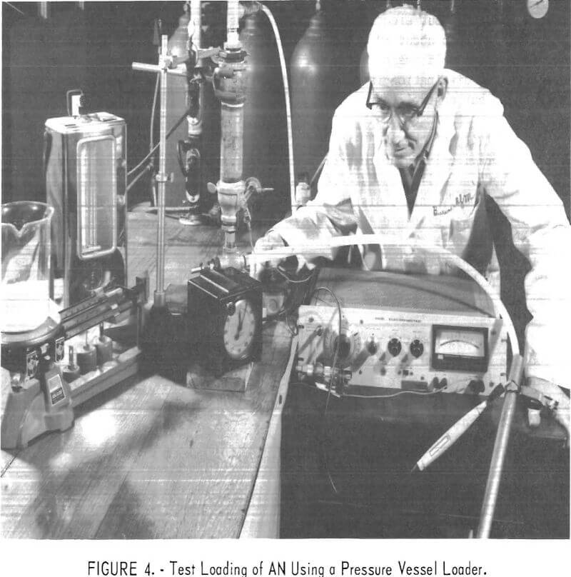
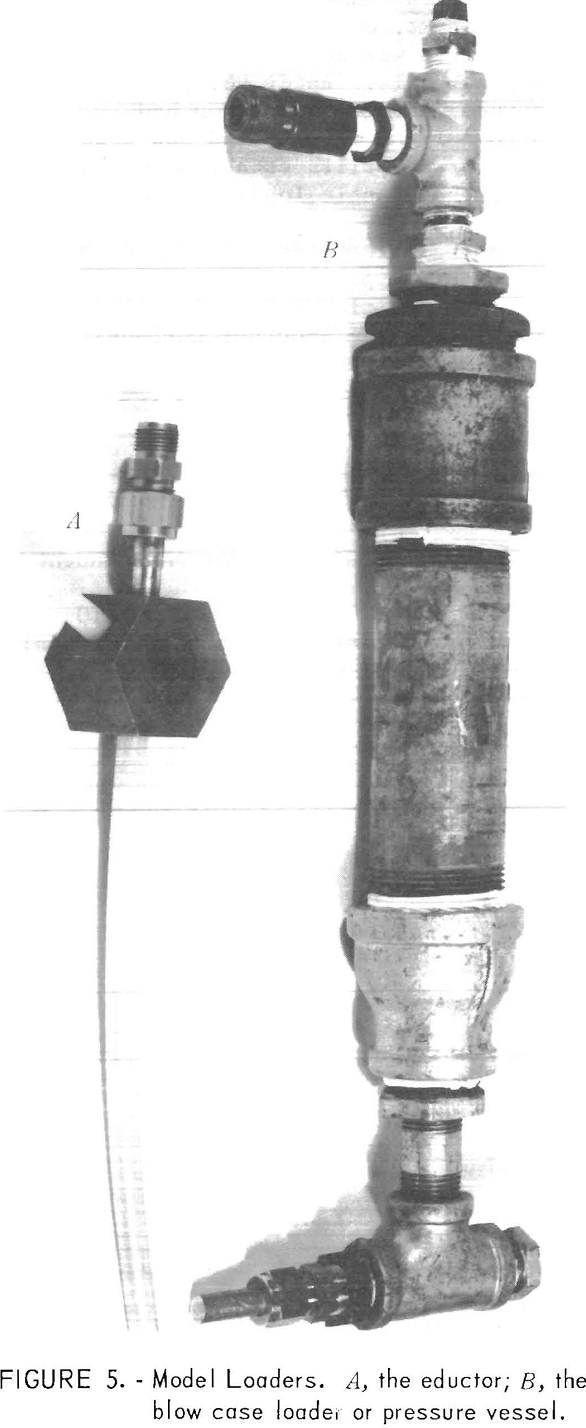
Both pressure vessel and eductor types of loaders were simulated. The test arrangement, with the pressure vessel loader, is shown in figure 4; details of the loaders are shown separately in figure 5. The pressure vessel loader was constructed from pipe fittings; it had a maximum capacity of about 0.75 pound AN. The loading tube was 0.5-inch-id polyethylene. The eductor loader had a high pressure air orifice of 0,040-inch diameter; the tubing was 0.25-inch-id polyethylene.
Loading rates were determined as functions of air supply pressure for both types of loaders. The data showed the laboratory loaders to be
satisfactory scaled versions of the commercial loaders they were intended to simulate. The observed loading rates were somewhat sensitive to prill type and to the smoothness of the loading hose.
Knowledge of the prill loading rate was necessary to permit correlation of electric current with prill charging rate. The most satisfactory situation would be that in which mass loading rate, and consequently prill velocity in the loading tube, was constant during the trial run. The eductor loader had essentially constant loading rate during a run and the loading rate of the pressure vessel loader varied less than 10 percent as the height of the prill bed decreased during a run.
Accumulated charge was determined with an electron tube electrometer and an integrating condenser. The accuracy of the individual charge determinations was about +3 percent.
The high pressure air was derived from a compressor in the laboratory, and was ballasted by 17.5 cu ft of tankage. The intake air to the compressor was dried by a small refrigerating dehumidifier and the compressor was drained frequently to minimize water accumulation. An ice water trap was attached to the ballast tanks. In this way the dew point of the high-pressure air is
believed to have been maintained at least as low as 32° F. The relative humidity of the supplied air was less than 2 percent. Variable air humidity for electrical conductivity measurements was obtained with conventional laboratory saturators. Attempts to construct a simple humidifier to give selected higher humidities to the high volumes of transport air required for operation of the model loaders were not successful.
Electrical conductivity measurements on prilled AN were made with the ohmeter section of a Kiethley 610R. Two different sample cells were used: One was cubical to permit reduction of resistance readings to the standard reference geometry for conductivity; the other was cylindrical and permitted air of selected humidity to be circulated through the cell to determine its effect upon the conductivity of the AN prills. The cell was made of polyethylene and was fabricated to have a contained 1-inch cubical volume. Two opposite faces were sheet metal with leads attached. The sixth side was open to permit easy filling of the cell. The data of figure 6 show that the electrical resistivity is extremely sensitive to moisture for both types of prills. The type 2 prills were more hygroscopic; the resistivity was one or two orders of magnitude less than that of the type 1 prills for the same conditions.
Early loading tests with prills of 10 11 to 10 13 ohm cm resistivity showed the existence of a conditioning phenomenon in the type 1 prills.
Tests with the rough surfaced prills, taken from the manufacturer’s container, gave consistent results, from one batch to the next, on the first run through the loading tube. If a particular batch of prills was reused, for additional tests, the charge generation increased systematically. After the prills had traveled about 50 feet through the loading tube, charge generation had increased by about 50 percent, as compared to a fresh sample, and had become stable. Tests with conditioned and then with fresh prills established that the conditioning was of the prills and not of the plastic loading tube.
Type 2 prills did not exhibit a conditioning effect and gave charge accumulations comparable to those from the conditioned type 1 prills. The type 2 prills were quite hard and smooth surfaced; the conditioned type 1 prills were noticeably smoother surfaced than fresh type 1 prills. Smoother surfaces would be expected to increase the prill tube charging contacts and give more charge generation.
It was concluded that the conditioned type 1 prills were the best approximation to a “typical” prilled material issuing from a loader. The majority of the tests were then conducted with this material.
For both kinds of loaders, the total charge accumulation was independent of the loading rate and the electric current was proportional to the loading rate. The charge generation per unit weight of prills loaded was about 10 times larger from the model eductor loader than from the model pressure vessel loader. For given air supply pressure, the current from the eductor was less than from the pressure loader because of the lower mass loading rate of the eductor.
The differences in charging between the two loaders may be due to the differences in scale factor, especially to the differences in surface-to-volume ratio of the output tube. However, it remains that two different types of loaders, or perhaps two different scales of loaders, can produce appreciably different currents when operating at the same mass loading rate.
Prugh and Rucker have given a correlation between current and resistivity for all conditions covered by their investigation. The difference in charge production between the different loaders shows that one such curve cannot apply to all sizes and types of loaders.
Unconditioned prills were weighed into several jars and known amounts of water equal to between 0.02 and 3.6 percent by weight of the AN were added. The jars and contents were shaken occasionally but were otherwise left undisturbed for periods of 1 to 7 days. Substantially complete equilibration of the electrical resistivity of the prilled material was demonstrated to occur within much shorter time spans. The moistened prills were then tested under conditions as nearly identical as possible.
It was observed that charge accumulation during test runs with the moisturized prills was dependent upon the type of loader used,upon the conditioning of the loading tube, and upon the quantity of added moisture. In pressure vessel loader tests, samples containing 0.2 percent, or more added moisture gave evidence of somewhat decreased charge generation as compared to dry samples. Samples with 3.6 percent added moisture caused less than 50 percent of the charge accumulation of dry prills. Dry prills and prills with 3.6 percent added moisture gave nearly identical results when tested with the eductor loader. A sample containing 4.8 percent added moisture gave negligible charge accumulation when loaded with the pressure vessel loader but gave 30 percent of the dry prill value when tested with the eductor loader.
It was demonstrated that this difference in relative response of the two types of loaders to prill moisture content was due to the dryness of the transport air supplied and to the relative differences in consumption of transport air in loading a fixed quantity of prills. During passage of the prills through the pressure vessel loading tube, the damper and softer prills deposited a coating of AN on the interior of the loading tube and thereby changed the tube’s effectiveness in providing electrical insulation. In the eductor loader, the relative rates of supply of moisture and air were such that the tube was relatively dry and clean for much larger relative moisture contents of the prills.
When the moisture was supplied in the transport air rather than in the prills, the results were similar to those obtained from damp prills and dry air. In both cases the reduction in charge accumulation with moisture addition was qualitatively similar to the results given by Prugh and Rucker. Rather than one universal correlation, these results indicate that specific relationships should be applied to different types of loaders.
Recommended Practices and Procedures for Minimizing Electrostatic Hazard
In addition to all normal safety practices in the handling of electric blasting caps or electric bridgewire detonators, it is strongly recommended that the operator:
- Test to assure continuity of the electric detonator legwire-bridgewire-legwire circuit prior to insertion of the cap into charge or borehole. This testing should be accomplished with an electric blasting cap galvanometer suitable for use with the type of cap being employed in the blasting operation.
- Keep the legwires shunted but not otherwise connected to ground during loading of the blasting agent into the borehole. This will minimize the possibility of extraneous stray currents through the legwire to shell circuit. Detonators with plastic shells, and with the insulation on the lead wires in good condition may have the shunted legwires grounded if desired.
- Assure that the borehole is discharged prior to hooking up the detonator leads. This assurance is provided by burden resistivities of less than about 107 ohm cm, reduction of the charge delivered to the borehole and discharge of the borehole during loading through control of resistivity of the AN-FO and use of a semiconductive loading tube, and dampening of the shot hole walls and use of an additional return path from the borehole.
- Assure that the operator is discharged prior to handling the detonator leads. The simplest way of assuring that the operator is discharged is to have him discharge himself immediately prior to handling the leads.
- Assure that the blasting cap leads are never carried to the AN-FO loader. This will further minimize possible hazards from stray currents and hazards from such things as charged loader cases.
Adherence to the recommendations (1, 2, and 3) should remove any electrostatic hazards associated with the bottom-primed hole. Collar priming remains preferable, however, since it minimizes the probability of mechanical damage to the cap. Collar priming also minimizes any hazard from stray currents, from the power distribution system or from lightning, by minimizing the “exposure time” of the initiator. In collar priming, assurances that the borehole is discharged can be obtained as simply as with the operator: a grounding wire can be attached to two metal plates one of which is positioned near the operator’s feet and the other brought into contact with the loaded column of AN-FO prior to insertion of the priming charge.
