Table of Contents
This is one of a series of reports prepared by the Federal Bureau of Mines on mining methods, performance, and costs at individual mines in the United States. The primary purpose of these papers is to promote development and conservation of our mineral resources by disseminating technological information on methods, practices, and results that may be applied to the engineering analysis and solution of mining problems.
This report discusses the highly selective mining methods of the Jaquays Mining Corp. at the Regal asbestos mine, 45 road miles northeast of Globe, Ariz. The milling method at the Globe plant is discussed briefly, and the extraction ratios of the various grades of fiber are tabulated. The proposed flowsheet of a new mill under construction is shown.
The Jaquays Corp. purchased the Chrysotile property (old Johns-Manville mines) about May 1, 1959, and immediately started rehabilitation work. No detailed data are available to the author on work done by Johns-Manville in the 1940’s or on that done by subsequent operators after the sale of the property in 1951. However, as a historical note, the operation in 1930-31 is briefly discussed and various operating costs are given.
A brief discussion of the general geology and mode of occurrence of asbestos is essential to an understanding of the mining methods employed.
The asbestos-bearing strata of central Arizona are in the Precambrian Mescal limestone formation of the Apache group. Dripping Spring quartzite underlies and Troy quartzite overlies the Mescal formation, which is divisible into three members: A lower member 175 to 200 feet thick; an algal-limestone member 80 to 100 feet thick; and an upper member 10 to 80 feet thick.
In the lower member, the individual beds range from 1 inch to 6 feet in thickness. The thin beds are impure dolomitic limestone; the thicker, more massive beds are relatively pure crystalline limestone and occur within the topmost 45 feet of this member; most of the asbestos deposits of the region are within this stratigraphic interval.
The algal-limestone member, which overlies the lower member, is massively bedded and usually is composed almost entirely of spheroidal masses that have a concentric, shell-like structure with a maximum diameter of several inches. It generally forms cliffs and is the most readily recognized horizon marker in the Mescal formation.
The upper member consists of layers of siltstone (usually brown to black), thin shale, and sandy or shaly limestone beds. This member is present only in a few places in the region.
The Apache group has been intruded by diabase sills a few inches to several hundred feet thick. The sills usually are found along bedding planes, but locally they may cut across the bedding. Diabase dikes, most of which are only a few feet wide, also have intruded the limestone.
Asbestos invariably is found in veins within bands of serpentine. The veins vary from a fraction of an inch to several inches thick and roughly parallel the border of the enclosing serpentine. This serpentine and associated asbestos were formed within favorable limestone beds that were adjacent to or relatively near a diabase intrusion. The greater the folding or fracturing of the beds caused by the intrusion, the larger the deposit is likely to be.
Arizona asbestos is of the chrysotile variety, a hydrous magnesium silicate with the same composition as serpentine. The fibers of chrysotile occur as cross fibers; that is, the fibers of which the material is composed and into which it may readily be separated lie approximately perpendicular to the walls of the vein.
Cross-fiber chrysotile occurs as two distinct types, harsh and soft. Soft fiber feels smooth or soapy and can be twisted and bent between the fingers. The individual fibers usually are extremely flexible and strong. Harsh fiber is splintery, prickly, and somewhat brittle, so a small bundle of it breaks if twisted a number of times. All gradations between the harsh, brittle fiber and the soft, silky fiber can be found in the region.
A more detailed discussion of the general geology and mode of occurrence is presented in “Chrysotile-Asbestos Deposits of Arizona”.
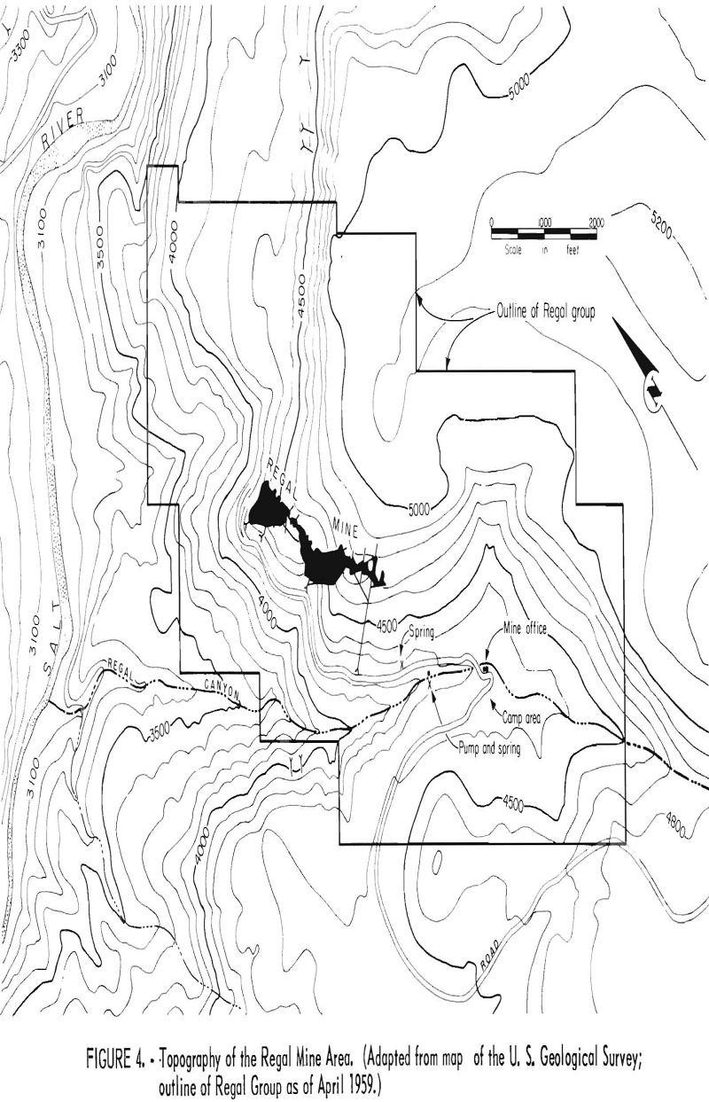
In the vicinity of the Regal mine the three members of the Apache group are exposed.
The asbestos-bearing serpentine zones within the mine area occur at three horizons in the lower limestone member of the Mescal formation. One zone is immediately under the base of the algal member; the other two are 29 and 35 feet lower in the section. The lower two have been the most productive. The lower zone is 19 feet above the top of a concordant diabase sill that is at least 300 feet thick.
A persistent 1- to 3-inch band of impure dark bluish-green serpentine occurs along a bedding plane at 21 feet above the diabase contact. The lower ore band is about 1 foot below and the upper ore zone is 5 feet above this serpentine band. It is locally called the “oscar;’, is found in all parts of the mine and along the surface outcrop, and is a reliable marker that indicates the favorable beds. The location of the ore bands is very important to an understanding of the mining method now in use.
In the mine area, the predominant factor in the concentration of asbestos within the favorable beds has been the shattering and warping of these beds by a belt of thrust faults. The belt has a general course of S. 25° E. Structural deformation has been caused by the underlying diabase intrusion. Asbestos ore is present on the limbs of folds and flanks of domelike structures and occurs in greatest concentration where small thrust faults cut these dipping beds. As the beds flatten, the asbestos content decreases.
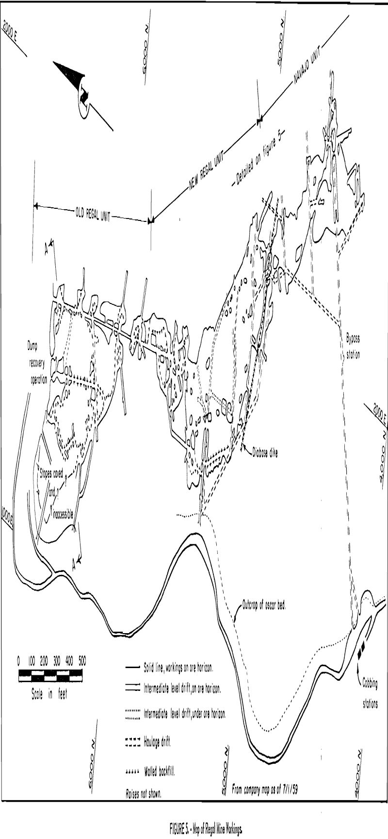
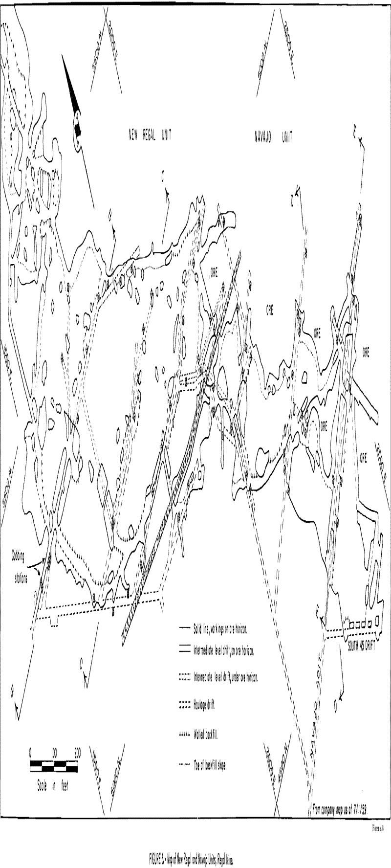
Although the mine workings are continuous along the mineralized Regal fault zone, production has been attained from three interconnected mine units, herein defined as the Old Regal, New Regal, and Navajo workings (figs. 5 and 6).
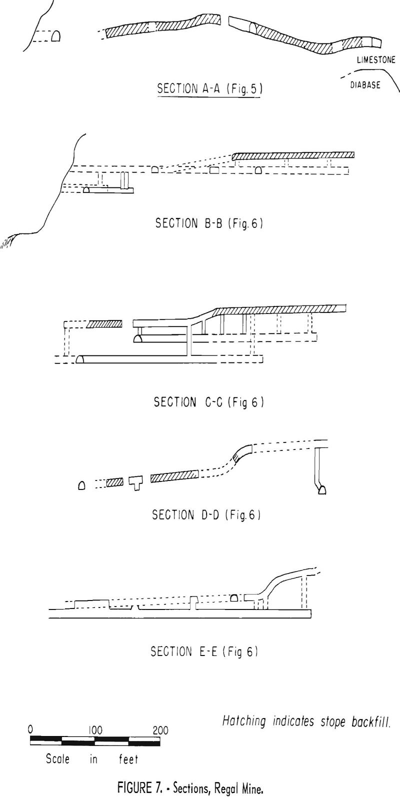
In the Old Regal workings, a network of faults associated with the thrusting formed a domelike structure (sec. A-A, fig. 7). Along the east side of the mine at the north end, the asbestos mineralization terminates when the underlying diabase sill cuts discordantly downward.
In the New Regal workings, the fault pattern consisted of several parallel thrusts that gradually stepped up the ore horizons into a monoclinal structure (sec. B-B, fig. 7). At the south end of the workings a postmineralization 7-foot vertical diabase dike was encountered. It strikes N. 72° W. and cuts the limestone and underlying diabase sill. Buckling of the limestone beds and the development of gouge along the dike walls indicate fault movement, but the slip is only a few inches. The only noticeable effect on the fiber zones is the increased harshness of the asbestos for a few feet on each side of the dike.
In the Navajo workings, an abrupt steepening in the moderately sloping beds is caused by a southeast-trending flexure that places about 20 feet of the ore zones in a nearly vertical attitude (fig. 7, sec. D-D).
Mining has been conducted southward along the course of the mineralized fault zone for 2,500 feet. The stopes at the south end of the mine are approximately 550 feet below the surface. The limestone formation west of the Regal fault zone lies relatively flat, and in the stratigraphic interval in which the mining operations are conducted the thickness of the individual beds varies from 6 inches to 3 or more feet. The limestone is compact, fine grained, and moderately hard, but drills fairly easily and breaks well. No supports are needed in drifts and raises.
The diabase encountered in development drifts and raises below the limestone section is a compact, homogeneous, fine- to medium-grained rock, some-what harder than limestone, but the diabase drills, breaks, and stands about as well as the limestone. Because there are no bedding planes in the diabase, the back holes and lifters need to be drilled closer to the top and bottom of the drift.
The 6- to 12-inch serpentine-asbestos band of the upper ore zone is at the bottom of a 3- to 4-foot limestone bed. It is a competent member that forms an excellent stope back. Openings up to 50 feet wide have been left unsupported during stoping operations, but usually the placing of backfill decreases the unsupported width to about 20 feet. As stoping progresses, the roof gradually flexes downward and settles on the backfill without fracturing. Pillars are left in areas that are intensely fractured.
The approximate weight in place of 1 cubic yard of the serpentine-asbestos material of the ore zones is 4,200 pounds; of limestone and diabase, 4,500 and 5,000 pounds respectively.
The degree of mineralization of the two fiber-bearing bands is not continuous; usually both are minable, but occasionally only one contains commercial asbestos. A peculiarity of the deposit is that if the asbestos content of one of the zones becomes insignificant, the other generally becomes better than average.
Methods of Prospecting and Exploration
The prospecting phase on the Regal ore body was relatively simple, because asbestos-bearing serpentine cropped out in the limestone cliffs on the south rim of Salt River Canyon. The first prospectors soon delineated the 400 feet of asbestos-bearing strata with pits and opencuts and then extended drifts into the better parts of the ore body. Although the favorable beds can be traced nearly a mile along the hillside on the east side of Regal Canyon, the outcrops have no ore, and surface prospecting is useless.
Adits driven to intersect the ore body in advance of the underground workings are considered by the company to be development work rather than exploration work. When these development adits are extended under the ore zones in advance of stoping operations, occasional holes are drilled upward to check the asbestos content of the ore horizon. Holes up to 25 feet long are drilled with the same feed-leg machines used in drifting, except that 3-foot sectional steel is used.
When the diabase dike was encountered at what was then the south end of the mine, there was a question of continuity of the ore deposit south of the dike. Exploration to check the ore horizon in advance of the workings was accomplished by long-hole drilling from several setups. A 4-inch jumbo-mounted drifter drill with an 8-foot chain feed was used. The machine was capable of drilling up to 150 feet at an inclination of 30°. Eight-foot sections of 1-inch hexagonal steel were used with a 2-¼-inch 4-point bit set with tungsten-carbide inserts. Drilling water from a nearby sump was recirculated with a pneumatic 3- by 2- by 3-inch duplex reciprocating piston pump mounted on the jumbo. The average drilling rate of this rig was 150 feet per shift.
At other places in the mine, exploratory drilling had been done with a small pneumatic diamond drill. Its use did not prove satisfactory, as the progress was slow and the asbestos fibers tended to plug the bit.
In 1958 it was decided to test the structure by drilling on the projected strike of the Regal fault zone, about one-half mile southeast of the Navajo
adit site. A pilot road was constructed up the hillside to drilling sites northeast of the camp. A 4-½-inch pneumatic track-mounted drill was employed, using 10-foot sections of 1-¼-inch hexagonal steel with 2-¾-inch 4-point bits and tungsten-carbide inserts on the cutting edges. The limestone was found to be shattered and blocky, and after making several unsuccessful attempts to penetrate the formation this exploration program was discontinued. None of the holes was deep enough to encounter diabase.
Method of Estimation of Tonnage Value
The cutting of face samples in an asbestos mine to determine the percentages of the various grades is considered impracticable. Jaquays has devised a visual method of determining the face value of the headings. He estimates the average cumulative thickness in inches of all fiber veins in the heading and the fractional parts of the vein that represent each of the four crude grades. For proportionate calculations, the value assigned to each inch unit in the discussion that follows is the average market value per ton of that grade: No. 1, $1,500; No. 2, $900; No. 3, $400; No. 4, $200.
As an example, there is an average cumulative thickness of 2 inches of fiber in the working face that has 1 inch of No. 1, ½ inch of No. 2, and ¼ inch each of Nos. 3 and 4. The value per ton of such fiber is quickly estimated on the inch basis: 1 inch of No. 1 = $1,500 x 1 or $1,500; ½ inch of No. 2 = $900 x ½ or $450; ¼ inch of No. 3 = $400 x ¼ or $100; and ¼ inch of No. 4 = $200 x ¼ or $50, a total of $2,100-inches, or a fiber value of $1,050 per ton ($2,100-inches) ÷ (2 inches). Dividing $2,100-inches by 84 (the average height of the working face in inches) gives a value of $25 per ton of rock to be broken, or “face ton” as it is called at this mine.
By experience, Jaquays has determined that the cut-off point for profitable mining is $12 per face ton. He states, “Bands of asbestos totaling only 1-½ to 2 inches of fiber may be mined profitably in a 7-foot-high heading, if at least half of the fiber is No. 2 grade or better.” An example of near-minimum value would be 1-½ inches of fiber showing ¾ inch No. 2 or better (about one-third of the fiber is No. 1), ½ inch of No. 3, and ¼ inch of No. 4. The “dollar-inch” value would be: No. 1, $1,500 x ¼ or $375; No. 2, $900 x ½ or $450; No. 3, $400 x or $200; and No. 4, $200 x ¼ or $50, giving a total of $1,075-inches. The face-ton value then would equal $1,075-inches divided by 84 inches (height of working face) or $12.80. The fiber value in this case would be $1,075-inches ÷ 1.5 inches, or $717 per ton.
In this example, if there was no No. 1 fiber, the face-ton value would be $11, below the cut-off value for profitable mining although the fiber value is $616 per ton.
However, in cases where more than 1-½ inches of fiber shows, a lower dollar value fiber can be mined as long as the face-ton value is over $12 per ton. As an example, 2 inches of $600 fiber or 3 inches of $400 fiber would give $1,200-inches, which is about average for the Regal mine.
Development And Mining (General)
Old Regal Workings
The Regal mine originally was developed by several adits along an outcrop that was exposed for about 400 feet along the cliff face. The adits eventually were connected as stoping progressed. Random pillars were left and as much waste as possible was hand shoveled into the backfill. Three raises were put up to test the ore horizon 30 feet above, but at that horizon only one small area at the north end of the deposit was productive. Except for the adit on the east side of the deposit, the entries have become inaccessible, as has the stoped area near the surface. A description of the mine in 1928 was published by the Arizona Bureau of Mines.
When the Jaquays Mining Corp. purchased the property in 1952, the mining area was about 1,000 feet from the portal of the east adit.
New Regal Workings
In 1953 the New Regal adit was driven from a cliff face west of the ore body to intersect the mineralized area about 350 feet south of the old workings. The adit as situated 65 feet above the road and 2 feet above the oscar bed. Concurrently with this work, a haulage level was driven 20 feet beneath, and waste and ore transfer raises were put up to the adit above.
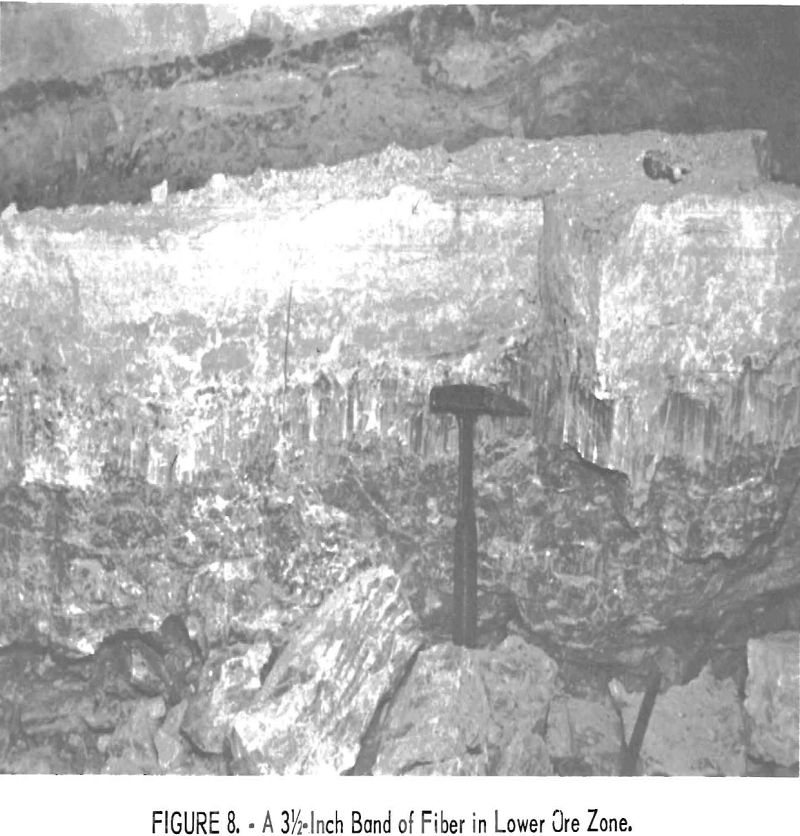
Commercial ore was encountered at floor level, 100 feet from the portal of the New Regal adit. Drift pillars, 75 feet long by 15 feet wide, were left, and stopes were developed north and south of the pillars. Figure 8 shows a block of ore that has been pried from the face. It represents the full thickness of the lower ore zone, the top of which is a 3-½-inch band of fiber. The oscar marker bed that overlies the ore zone can be seen in the wall.
Owing to the gradual rise of the ore horizon as the adit level progressed eastward on a tramming grade, the adit passed under the ore zone, and stope drifts were required to open the stope panels. Raises became necessary to transfer the ore from the stopes to the adit level, which in effect now had become an intermediate level and will be so-called hereafter (fig. 7, sec. C-C). A cobbing grizzly had been installed over a two-compartment raise, 50 feet inside the portal, and later it became necessary to install a second
similar cobbing station nearby. From separate chutes on the haulage level below, the waste and the cobbed ore were trammed to the surface.
The haulage level was extended beneath the southwest fringe of the ore body, and laterals were extended eastward under the area to be mined. Raises were driven to the ore horizon for disposal of waste from the mining operations. Because the cobbing stations were situated on the intermediate level, tramming of ore necessarily was confined to that level.
When driving the intermediate and haulage drifts, the muck was loaded into cars by means of portable ramp loaders, on which were mounted double-drum, air-driven slusher hoists.
Navajo Workings
In order to develop extensions of the ore body indicated in the advanced workings of the New Regal mine, the Navajo adit was started early in 1957. It was situated 1,200 feet farther to the south and driven on a bearing to intersect the mineralized area about 500 feet in advance of the New Regal workings. The elevation of the portal track was calculated to meet the interior grade of the New Regal haulage level. Fortuitously, this elevation was 8 feet below the marker bed, and, except for minor fluctuations, the bed was the back of the adit for 850 feet, at which point commercial ore was encountered.
On the assumption that the attitude of the ore horizon would be similar to that encountered in the New Regal workings, a more economical mining method was designed. The main drift was to serve for both waste and ore haulage; the latter was accomplished by placing the cobbing station outside the portal. When the ore horizon inclined above the haulage level, it was developed from raises and stope drifts, thus eliminating the intermediate level.
All drift and stope drilling is done with a 2-5/8-inch bore air-leg drill with a 3-foot feed, using one-piece, 7/8-inch hexagon steel with a 1-5/8-inch chisel bit set with tungsten-carbide inserts. Raising usually is done with the same type of drill, but it has a 3-foot telescopic feed lift. The operator stated that this particular combination of drilling equipment was selected after considerable experimentation.
Only 6- and 8-foot lengths of drill steel are purchased. Usable shorter lengths accumulate from steel breakage. When the break occurs near the shank end, the steel is re-shanked; if it occurs near the bit end the steel is upset and threaded for use with screw-type detachable bits, or tapered in the company shops for one-pass carbide bits. Any one of these repairs costs $2.25 each. Both chisel and 4-point detachable tungsten-carbide insert bits are available at the mine. The latter, attached to short steel, generally are used for drilling 1-foot pinholes for sheave anchors. For longer holes, the operator uses the chisel bit, which drills rock faster because of more efficient chip clearance and is superior to 4-point cross bits when drilling in fiber-bearing serpentine. The 1-5/8-inch hole provides ample room for the 1-1/8- by 8-inch dynamite cartridges.
Repair costs have been low, although 200 to 300 feet of drilling per machine is done each day. Chucks and water tubes require replacement approximately every 30 days, at a cost of not over 68 cents per operating shift. The average total life of the drills is not known; the oldest ones have been in use only 5 years.
In drilling with feed-leg machines, no steel changes are necessary; the hole is started and finished with one piece. The only bit sharpening done is touching up the cutting edges on a small pneumatic grinder.
When drilling the bottom ore holes at floor level, some miners prefer to use a conventional jackhammer. Two paving breakers also are available for hitch cutting in raises and for breaking pieces of ore too large to handle at the stope face; however, most of the ore sorters prefer sledging the pieces, as the ore is easily broken along planes of stratification.
All mine rail in the Navajo workings is 16-pound; the two older mines used 12-pound rails.
Development Details
The Navajo adit was driven 125 feet on company account. After the portal sets had been installed, a mucking machine was used. Timbering was required for the first 50 feet because of the shattered, near-surface rock conditions.
The timbered section has a minimum width of 6 feet and a clearance of 7 feet above track level. In solid rock the minimum cross section is 6 by 8 feet. Standard 18-inch gage track, using 16-pound rails on 4- by 6-inch ties spaced at 36 inches, was laid on a 0.75-percent grade. Previous experience had shown this to be the optimum grade for hand-tramming 20- and 30-cubic-foot mine cars.
Beginning at 125 feet from the portal, where the bearing of the adit was to be changed, the work was contracted. The contractor worked 2 shifts daily and, according to company policy, on a 12-day-on and 2-day-off basis. Six-foot rounds were drilled, using a one-piece, 6-foot drill steel and a 3-foot feed leg.
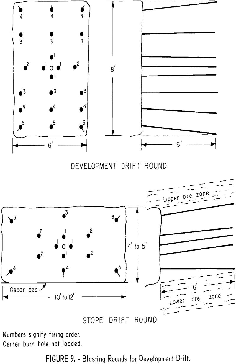
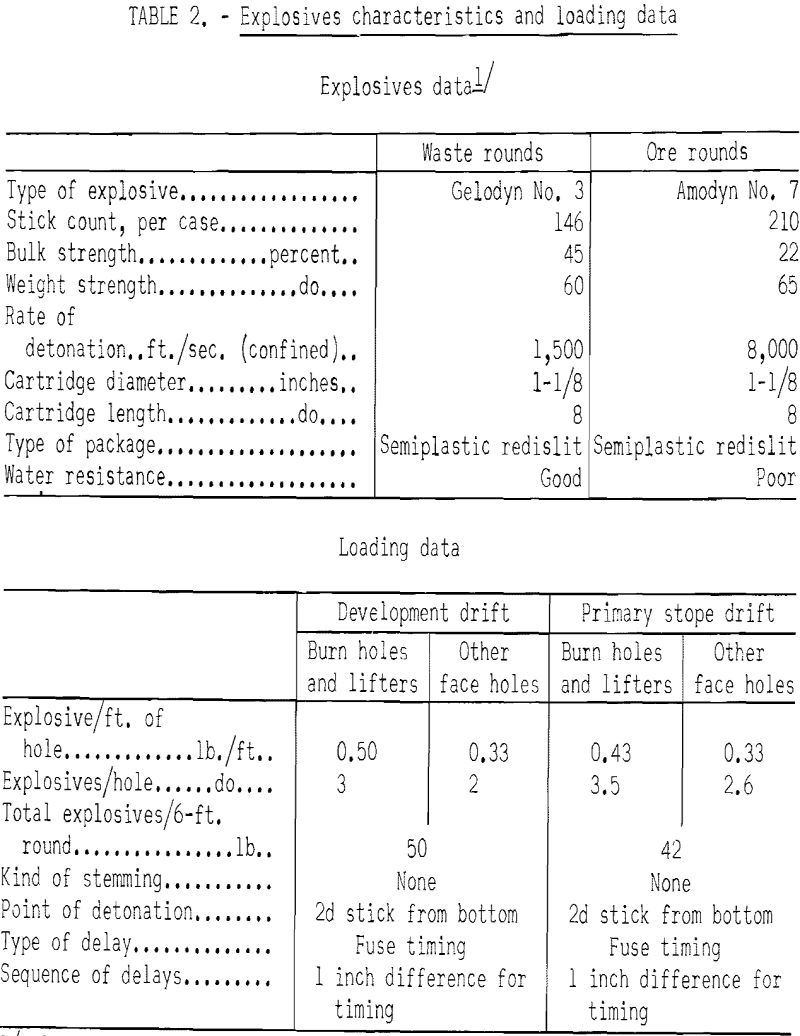
A standard development round, consisting of a total of 22 holes with a five-hole box-burn cut at the center, was used (see fig. 9). In this round the center burn hole is not loaded. Normally, the other four burn holes and the lifters are loaded with eight or nine sticks and the remainder each with six sticks of powder, all without stemming. Gelodyn No. 3, 45 percent semi-gelatin, redislit, 1-1/8- by 8-inch cartridges are used, detonated with fused No. 6 blasting caps ignited by a hot-wire fuse lighter; each round requires about a 50-pound box of powder. The round usually breaks to the bottom of the holes.
Electric blasting caps were used when driving through the water-saturated fold described under “Mine Drainage.” With only one heading, two men were employed on each shift, the miner doubled as mucking-machine operator and driller and the other man as trammer and helper. The first half of the shift was devoted to cleaning the heading of muck from the previous blast, usually loading 15 or 16 30-cubic foot cars and laying track, air, and water lines. Drilling, loading, and blasting required an average of 3 hours 45 minutes; minimum time was 1 hour less. The night shift, coming on 3 hours later, repeated the same sequence of operations. No timbering was required.
As development proceeded, and two or more headings became available, the crew of each shift was increased to two miners, a mucking-machine operator, and two trammers.
Soon after passing under the uptilted ore body, the development drifts entered diabase. The drilling time, rate of advance, and amount of dynamite used were virtually unchanged. The only variation to the standard drilling pattern employed in limestone was to drill the top holes and lifters closer to the back and floor. The variation was due to rock structure; limestone easily breaks to bedding planes, but diabase is homogeneous.
The development-drift contract was continued until the north drift was connected with the New Regal workings and the main adit and a lateral were well under the ore body. The main adit then was extended to the surface from the bend near the portal, a distance of 135 feet. After the first 60 feet, timbering was required and the company completed drifting to surface. With this second entrance in operation, surface disposal of waste was independent of the ore-delivery trackage.
The contract work then was shifted to certain stope drifts that would extend the stope faces that had been opened by the company concurrently with the later contract development drifting.
Contract work in stope drifts was confined to removal of barren limestone between the two ore zones. Stope drifts, restricted to the height of the waste band (4 to 5 feet), were driven 10 to 12 feet wide, following the inclination of the limestone bedding. A 6-foot round was blasted and slusher scraped to the nearest raise. After two rounds had been driven, the ore from both ore zones was removed by company miners as described elsewhere in this paper.
From this clean face, now 6 or 7 feet high, the primary stope drift operation was repeated. Payment for contract work of this type was on a cubic-foot basis, as were slabbing rounds in the development drifts for turnouts or widening for track curves in the development drifts.
A typical 15-hole drill round for removal of barren limestone in a stope drift is shown in figure 9. The holes, drilled parallel to the stratification, are placed so that the oscar bed will be the floor and the bottom of the upper ore zone will be the back of the primary drift.
The average loading was one stick of dynamite per foot of hole, with two additional sticks in each of the four burn holes and the three lifters, or a total of 42 pounds of Gelodyn.
After development had produced several headings and sufficient stope faces, contracting was discontinued, but the company continued a decelerated development program. In July of 1959 one miner was employed exclusively on extending development drifts and putting up raises. He started his shift at noon and occasionally drilled and blasted two faces daily. A mucking machine operator devoted the first half of a regular day shift to clearing development waste ahead of the afternoon driller.
The lateral development drifts are driven parallel to the main adit and spaced at 200-foot intervals. Raises normally are 65 feet apart, except where the attitude and irregularities of the ore body require closer spacing.
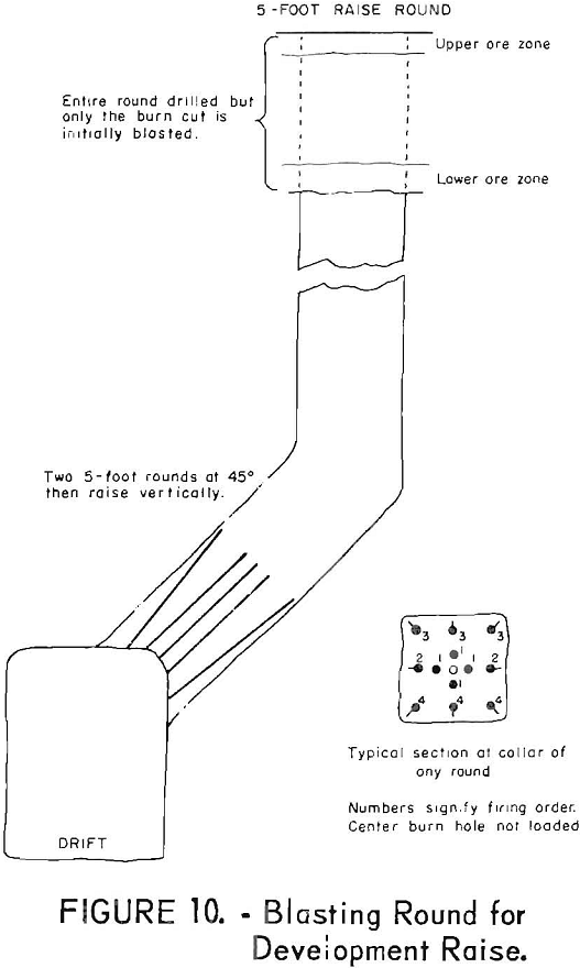
Raises with a minimum cross section of 4 by 4 feet are centered in the side of the drift at roof elevation (fig. 10). The raises are driven two 5-foot rounds at an inclination of 45°, then vertically to the bottom ore band. A 13-hole box-burn minature drift round is used. The center burn hole is not loaded. The other four burn holes are loaded with eight sticks each and the remainder of the holes with six sticks each, or a total of approximately 30 pounds of Gelodyn No. 3. When the bottom of the lower ore horizon is reached, an additional round is drilled and only the burn cuts are blasted. This serves as a visual check on the ore zones without wasting the fiber that would have been broken by a complete raise round. The remainder of the round is blasted after provisions have been made to recover the ore. Raise drilling is done either with the same machine that is used in drifting or with a telescopic leg machine.
A second driller is used to drive the stope and fringe drifts utilized in stope preparation. Although the drifting is confined to the ore horizon and some production is made therefrom, it is considered as development work.
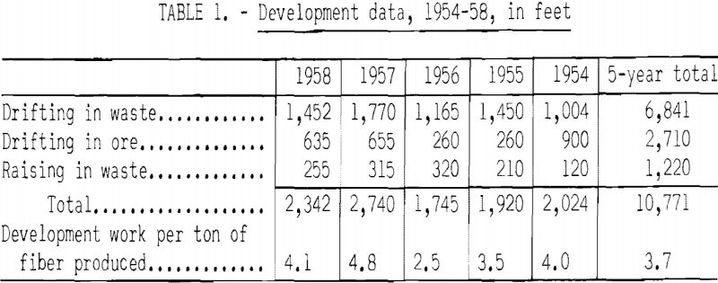
The amount of annual development work achieved is shown in table 1.
The characteristics of the explosives used and the loading data are summarized in table 2.
Stope Mining
A stope is prepared for full-scale mining by driving stope drifts 10 to 12 feet wide along the sides of the block to be removed and across the fringe or outer limit of commercial ore. The width of the block is determined by the alinement of raises from the haulage drifts, which usually are 200 feet apart. The method of driving the stope drift in the waste strata between the ore zones has been described. After two rounds of waste material have been removed, the asbestos-bearing bands are lightly shot and the broken material hand-sorted. The tenor of the ore in the two zones usually differs; therefore, blasting the upper and lower bands in separate operations allows the better ore to be sorted without excess dilution.
The lower ore zone usually is thicker and contains more fiber. Three 8-foot holes are drilled close to the bottom of the serpentine zone, spaced one at the center and one at each side of the drift about a foot from the wall. Some miners use the feed-leg machine, but others prefer the old “Finnish setup”, which is drilling with a conventional jackhammer that slides on a board on the floor. Each of the holes is loaded with three sticks of 22 percent Amodyn No. 7, merely enough to shatter the serpentine without fine fragmentation. After the ore is hand-sorted to separate waste and ore, the top ore band is blasted with three similarly spaced 8-foot holes drilled close to the back. Two sticks of the same low-strength dynamite are used in each top hole.
After the stope has been prepared for full-scale mining, the working face is nearly 200 feet long. Slushers are set at each end of the face, usually mucking into raises by scraping parallel to the face. If the stope is at haulage level, slusher ramps are used.
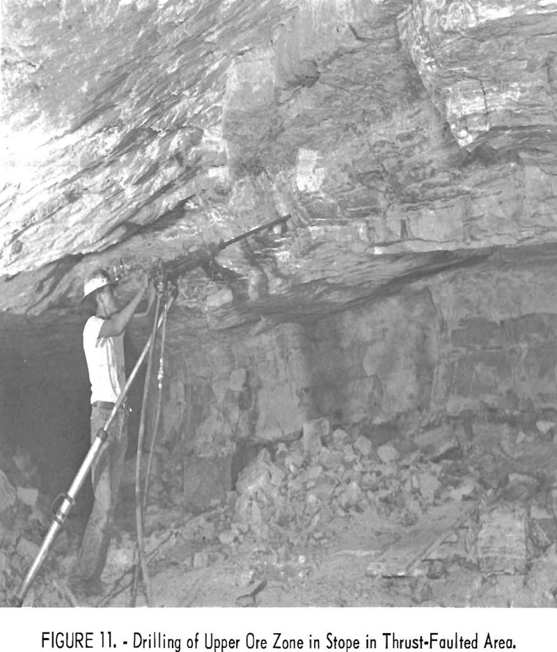
Stoping is conducted up-dip along one side of the stope drift (fig. 11), following the same sequence of operations described in stope drifting. Until there is space for backfill, much of the muck must be scraped into raises in order to clear a 5-foot-wide working space against the face. As the stope face advances, the material from the waste band is blasted into the backfill by proper hole spacing and pointing. Experience has shown that a burden of 2 feet on a blasthole gives the best breaking and propulsion combination for placement in the backfill 20 or 30 feet away.
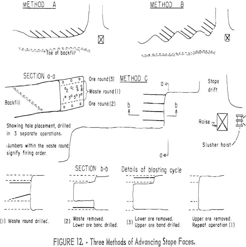
Three methods of face drilling have been employed, as shown in figure 12. In each case, two rows of 6- to 8-foot holes are drilled. The upper row is 12 inches below the bottom of the upper ore zone and parallel to the bedding. The lower row is drilled 18 inches above the oscar and is pointed downward so that the end of the holes is within a few inches of that bed. Method A is a continuous series of holes along the face. Usually, eight pairs of holes are
blasted at a time. This method is considered the least efficient, as it gives poor return on hole footage and requires at least another drilling and blasting operation to clear a sufficient bench width for economical fiber removal.
In method B, the holes are drilled into a serrated stope face. The principal objection is that the re-entrants cannot be cleaned with the scraper.
Method C is the preferred method of stope advancement. The drill holes in the waste band are parallel to the gob pile, and the blast packs the backfill more efficiently than angle holes. Each round creates enough room for efficient fiber removal.
Each hole of the lower row in the waste band is loaded with eight sticks of 45 percent Geolodyn. This heavy charge blasts the waste tightly into the backfill. The upper row of holes are loaded with six sticks of the same dynamite and are timed to follow the hole immediately below it. Thus, much of the material broken by the upper holes is blasted into the backfill by the succeeding explosion in the lower so-called wiper hole.
A unit crew consists of one driller, one slusher operator, two ore pickers, and a trammer. The waste close to the working face is slushed with a
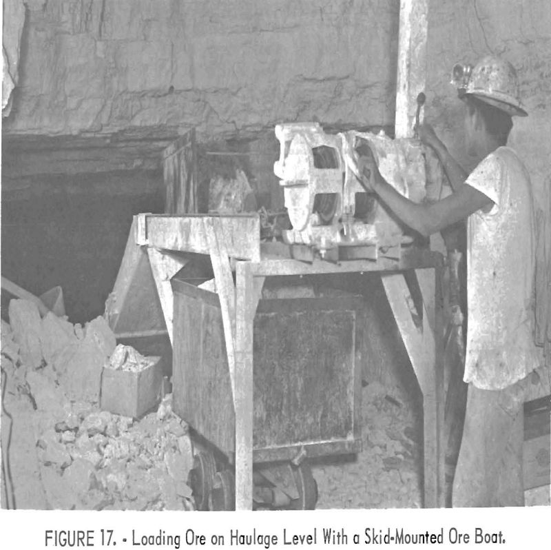
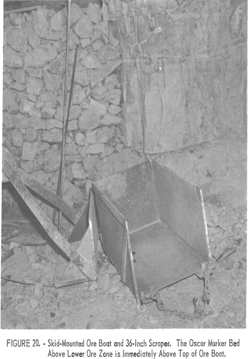
reversible hoe-type scraper. When loading ore, the scraper is removed and a skid-mounted ½-ton car (ore boat) is attached to the slusher cable. The ore pickers hand load the ore boat with fiber-bearing material, sorting out limestone and barren serpentine without resorting to cobbing, sledging only those pieces too large to be handled easily. The ore boat is pulled to the raise or to a slusher ramp for loading into regular mine cars.
Roof support in the Navajo and New Regal workings is accomplished primarily by tight backfilling. Pillars are necessary to support fractured areas where the roof is unstable and to protect the haulage drift where it is within the ore horizon. A pillar 30 feet wide also is left above the haulage drift when it passes below the ore zone. Pillars are not left where there is 15 or 20 feet of rock between the drift and the stope level.
Pillars near the haulage level are to be robbed on the retreat during the last stage of mining operations.
Random pillars are left where the ore tenor is submarginal. If these pillars are relatively small and are situated over haulage drifts, they are drilled for possible future blasting when signs of transmitted roof pressure become apparent in the drift below.
The limestone stratum overlying the ore horizon is relatively thick bedded and competent, but in time it tends to flex downward uniformly, adjusting the weight on the backfill. In general, pillars less than 10 or 12 feet in diameter are a detriment because they not only tend to be crushed, but also the resultant pressure that builds up around the periphery of the pillar cracks the overlying roof stratum. When the bed is broken, the roof in the immediate area becomes unstable and is apt to cave.
Although there are open stopes in the Regal mine up to 50 feet wide, supported only by posts, it is the present practice to keep the backfill within about 20 feet of the long-wall face.
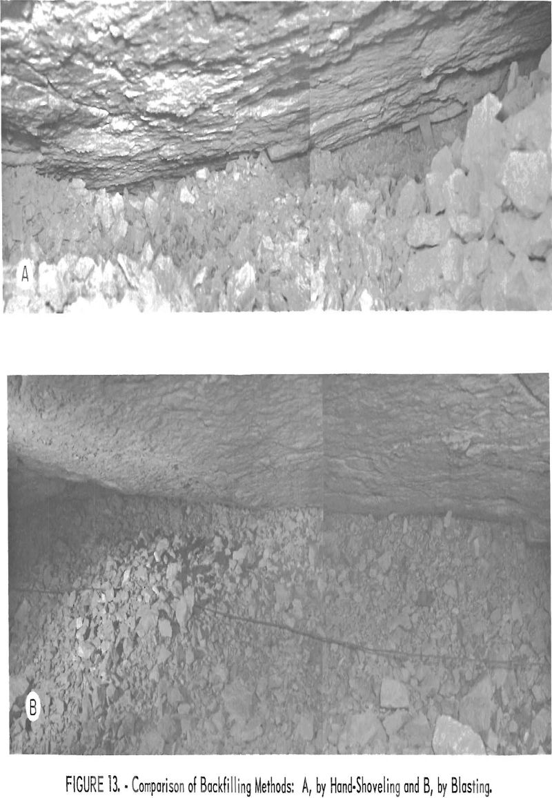
As indicated previously, backfilling is accomplished by a method of properly spacing, pointing, and blasting the drill holes in the waste band. The blasting operation not only compacts the waste but tightly packs the material against the back of the open stope. Manual or mechanical backfilling leaves an irregular surface that is not in contact with the stope back. See figure 13 for a comparison of the two methods.
The management estimates that 50 percent of the material broken in the mining operation remains in the backfill. This retention of waste in the mine is higher than that of similar asbestos mines where the waste is placed in the backfill by scraper or hand shoveling.
A detailed study of the percentage of waste remaining as backfill at the El Dorado mine of the Arizona Asbestos Association was made by the author in 1931. Random carloads of waste were weighed to determine the average car loading. Hand cobbing of the crude Nos. 1 and 2 grades was done in the stopes, and only the sacked crudes of these grades and the excess waste were removed from the mine. Detailed stope surveys to determine the volume of rock broken were made of the advancing stopes, and cars of waste trammed to the surface dump were counted. Waste was hand shoveled into the backfill, gobbed as tightly as possible, but the top of the gob pile was always ½ to 1 foot from the back. Over a period of 4 months, in which more than 11,000 tons of rock was broken, 45.2 percent was backfilled. Thus, the estimated 50-percent retention of waste in the Navajo and New Regal workings is conservative.
Dry walls occasionally are built to maintain necessary passageways through or around backfilled areas. The walls are not intended for support but merely keep the waste from spilling into the passageways.
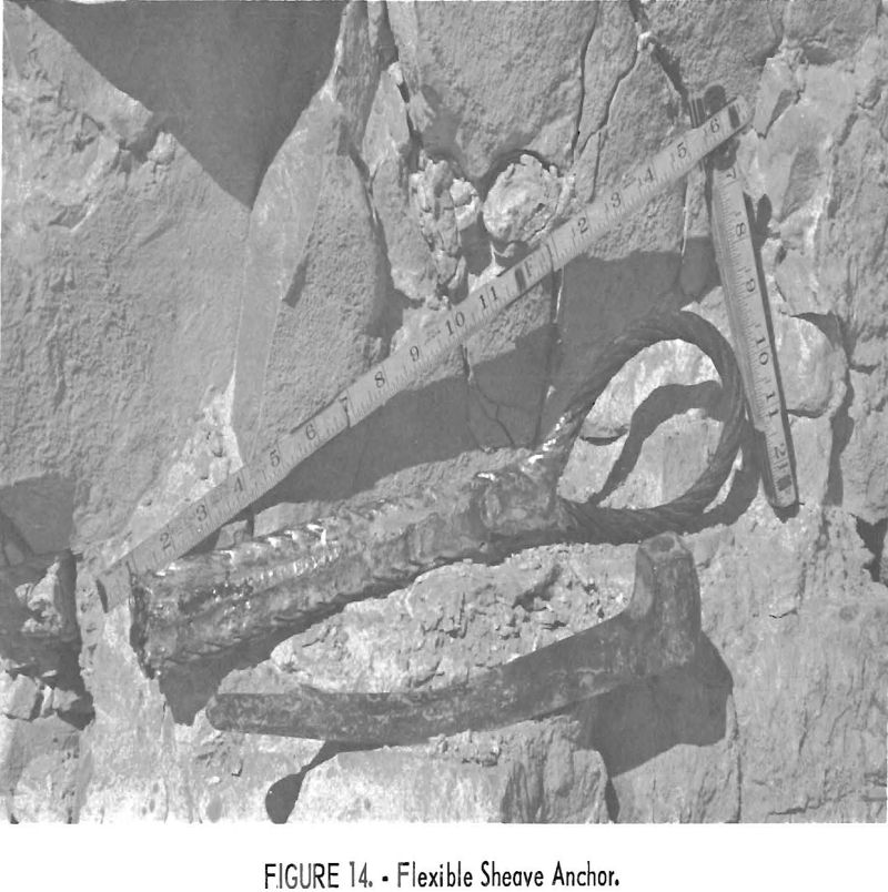
Because only double-drum slusher hoists are used, the direction of pull on the sheave anchors is variable and tends to crystallize the steel. After two near accidents due to broken anchors, the management decided to make its own sheave anchors. Each end of a 3-foot loop of 9/16-inch steel cable is brazed to a narrow 9-inch steel wedge (see fig. 14). When wedged, the semi-flexible corrugations of the cable and the brazed strips seat firmly against the sides of the pinhole, resisting loosening by vibration. The cable loop, which extends from the pinhole, flexes with the load.
Underground Transportation
The first operation involved in the transportation of ore and excess waste from the initial breaking point in the stope is movement by means of slusher hoists, regardless of whether the ore horizon is at or above the haulage level. If the ore horizon is at or within slushing distance (about 100 feet) of a haulage drift, mine cars are loaded from a ramp set over the track.
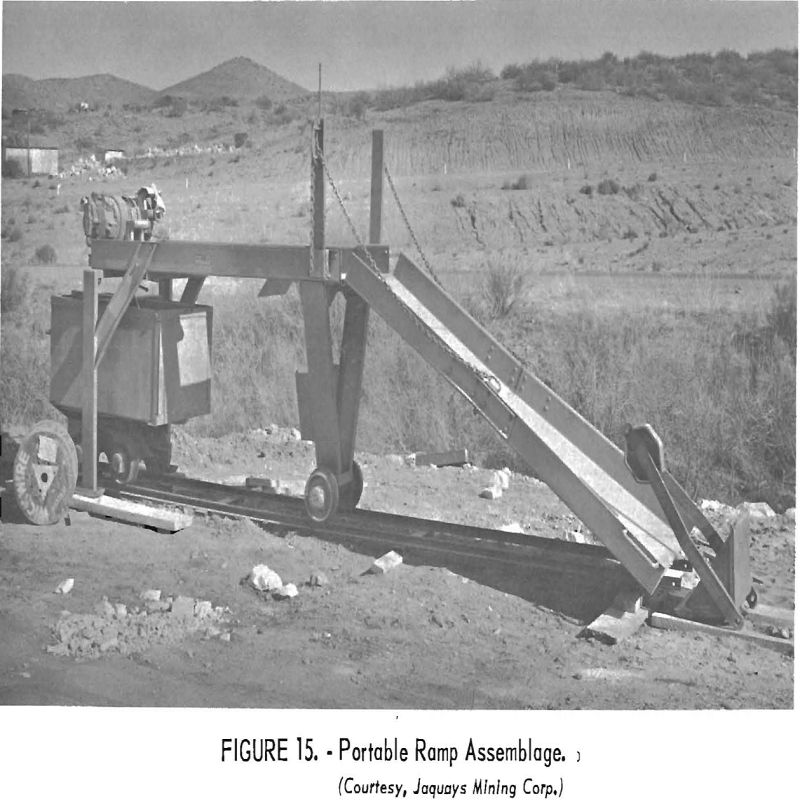
The portable ramp used is standard equipment at the Regal mine and is custom-built in the Phoenix shop of D. W. Jaquays & Co. at a cost of approximately $400. The entire ramp assemblage is illustrated in figure 15. Mobility is attained by supporting the rear end of the ramp on a mine car with a so-called spider that consists of 4-inch channel iron members welded in a right-angled cross and notched to fit the top of the car. The rear end of the ramp is lifted clear of the floor with a small screw jack built into the spider. The ramp then can be trammed to any desired place in the mine. The spider and jack are shown in place in figure 15.
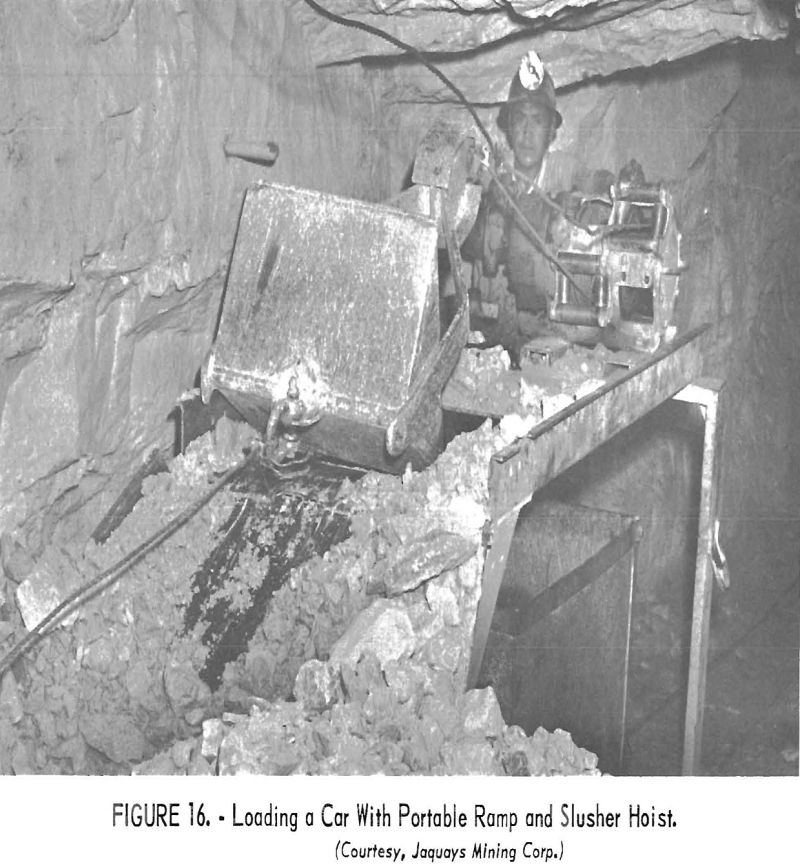
Figure 16 shows the method of loading waste with a scraper, and figure 17 shows a skid-mounted ore boat ready to dump.
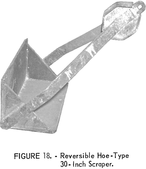
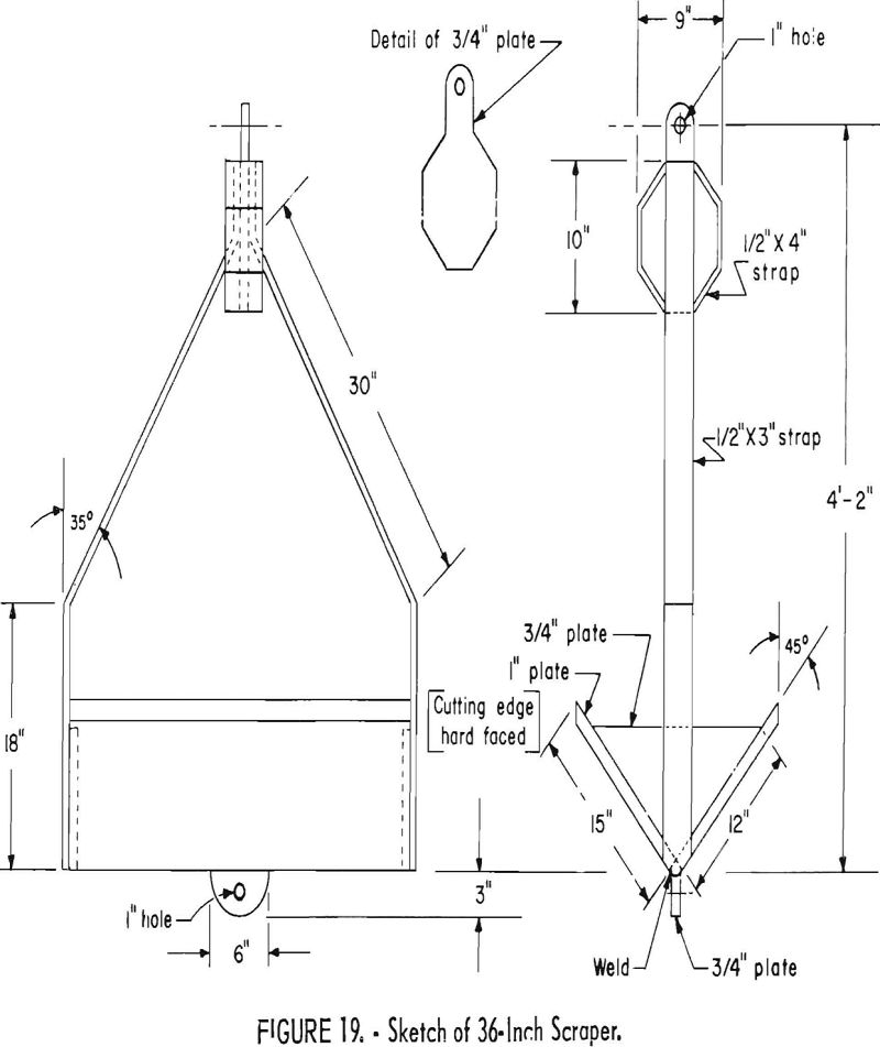
The reversible hoe-type scrapers are 30 or 36 inches wide. This type of scraper has been chosen for several reasons: (1) Its simple design makes it relatively cheap to build; (2) in case the scraper flips over, there is no lost time in manually righting the bucket as the opposite blade digs equally well; (3) it was especially designed to use most efficiently with available
slusher motors; (4) it loses none of its load while sliding up the inclined ramp. Experiments to determine the optimum performance of the scraper were conducted by varying the weight of the bucket. One-inch plate construction gave the most efficient performance
Figure 18 shows a 30-inch scraper, and figure 19 details the measurements of a 36-inch scraper.
The skid-mounted ore boats originally were made by removing the truck assemblage and door from old 20-cubic-foot mine cars., cutting down the sides to a height of 18 inches, and attaching a chain bridle to the upturned ends of two 4-inch channel-iron skids welded to the bottom. Now, ore boats are constructed in the shop with reinforced bodies of 3/16-inch steel plate (fig. 20)
From the stopes above the haulage level, the ore and waste goes into separate raises or into the same raise in different cycles. The ore or waste is loaded into end-dump mine cars by the underground trammer and pushed to the bypass station, some 600 feet inside the portal. This station is double tracked for about 70 feet to accommodate 12 loaded cars on the main line and 12 empties on the switching track. Spring switches keep the loaded cars on the mam track and bypass the incoming empty cars onto the switching track. On a plank between the tracks, 18-inch chains are attached at one end and can be kicked across one rail to keep the cars from rolling forward.
The underground trammer hangs a yellow metal tag on each car that contains ore, takes an empty, and returns for another load. The surface trammer kicks out the chain stop and pushes the car to the portal. Ore or waste cars are routed to their proper destination by a manually operated switch. Ore cars are either dumped onto the cobbing grizzly or sidetracked on the approach trestle for dumping as needed. As an ore car is dumped, the tag is taken off and placed on a spindle to be counted and recorded daily by the mine superintendent.
The waste cars are trammed over the other track to the dump. The trammer manually trips a car-counting meter installed inside the portal.
A car-retaining bumper that engages all four wheels is fastened to the end of each of the dumping tracks to prevent accidental derailment or loss of a car during dumping.
Chute construction is standardized in the Navajo workings. The chute floor is inclined about 40°, the overall width is 36 inches, and the chute lip is in line with and 50 inches above the inside rail of the track. Minimum clearance between posts and each side of the track is 12 inches, and the caps are at least 7 feet above the track level.
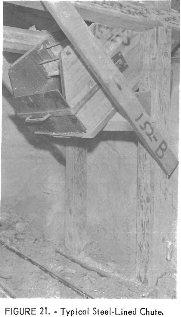
Because the users of asbestos products are becoming more critical of even small amounts of wood fiber in the milled asbestos, the operator uses steel-lined chutes. Prefabricated sectional steel liners and steel gates are placed in all new chutes; the old chutes are being relined with prefabricated steel sections as rapidly as possible. Rock flow is controlled with a modified over-cutting arc gate and checked by two “drop boards” that are channel-iron members sliding between welded guides. Figure 21 shows a typical lined chute, and figure 22 gives the construction details. The slotted bolt holes in side and bottom plates allow for variation of chute width.
The gate arm originally was attached parallel to the chute floor. The rocks of the first load dumped into an empty chute had the tendency to bounce the chute gate open. Raising the pivot point of the gate arm 1 inch eliminated the trouble.
Normally, the smooth side of the channel-iron drop board is placed against the material in the chute for easier raising. However, when a chute is used intermittently and drawn empty, the impact of rocks against the drop boards
often bounce them out of the guides. This is overcome by reversing the channels so that the flange side faces inward.
Auxiliary Operations
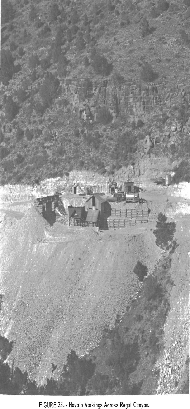
The surface layout of the Navajo workings is shown in figures 23 and 24. Minor equipment repairs are made at the portal where spare parts and small tools are available at the tool shed. Major repairs are made in the machine shop at the mill in Globe, or at the Phoenix plant of D. W. Jaquays & Co. in their large machine shop. At the Phoenix shop, the ore bins, belt conveyors, mine cars, slusher buckets, sectional steel chute liners, and other equipment are fabricated.
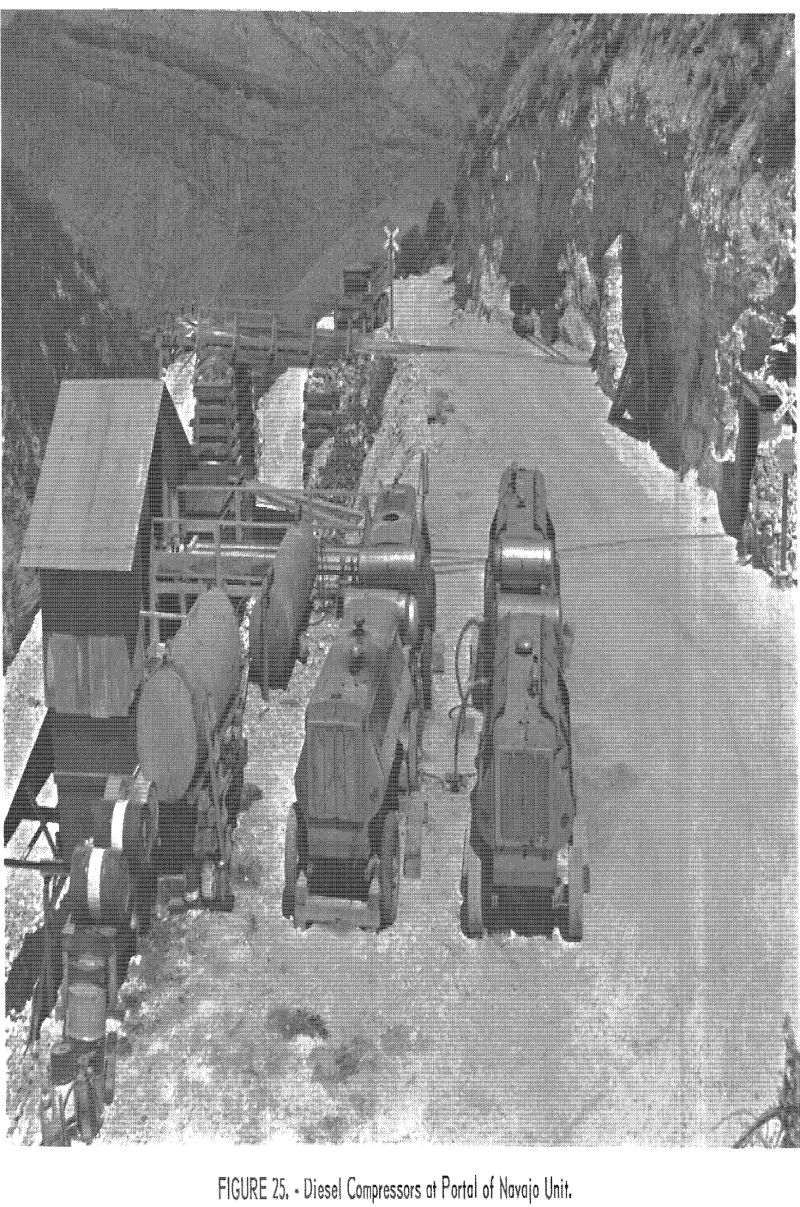
Compressed air is furnished by diesel-powered portable compressors. Three 500-c.f.m. and one 600-c.f.m. units are outside the Navajo portal and one 500-c.f.m. unit is at the New Regal portal. The four compressors at the Navajo workings are arranged in two tiers, back to back, directly connected to a 1,000-gallon fuel tank.
Each of these four compressors is connected to a 4-inch air line feeding into a 3-½- by 14-foot receiver (fig. 25). From the receiver, a 4-inch air line on the side of the drift floor goes 850 feet along the main adit, branching to a 3-inch line in the south 45 fringe drift. Wherever necessary, 2-inch lines carry air to the working faces. One of these 2-inch lines is connected through the mine workings to the portal of the New Regal adit where the fifth compressor and a 3- by 5-foot receiver are located. Two or three of the compressors are operated as needed during the shift; the others are on a stand-by basis. No 1-inch air lines are used in the mine.
The compressors are set to deliver air to the receiver at 100 to 105 pounds, or approximately 90 pounds at the working faces.
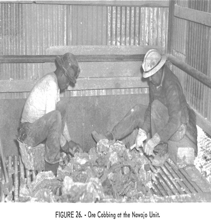
The cobbing platform, 8 feet wide by 20 feet long, consists of a longitudinal grizzly constructed of 12-pound mine rail set base up with ½-inch clearance between adjacent rails. A transverse 2-foot high V-shaped steel deflector divides the grizzly into two cobbing compartments, under each of which is a 10-ton bin. The whole assembly, constructed of steel, sets over a lower service road on the mine dump. The grizzly is 4 feet below the ore-haulage track and is covered with roof and siding of corrugated sheet iron (fig. 26).
The fines pass through the grizzly and the cobbed material is tossed through a 12-inch-wide aperture at the outer end of the grizzly rails into the bin below. Waste material is thrown or shoveled out of a slot in the side of the shed, and as it piles up occasionally is pushed off the dump.
A second and somewhat larger cobbing structure, now being installed, will be used for cobbing ore that is lime-free, the fiber of which will be used for specialized filtration products.
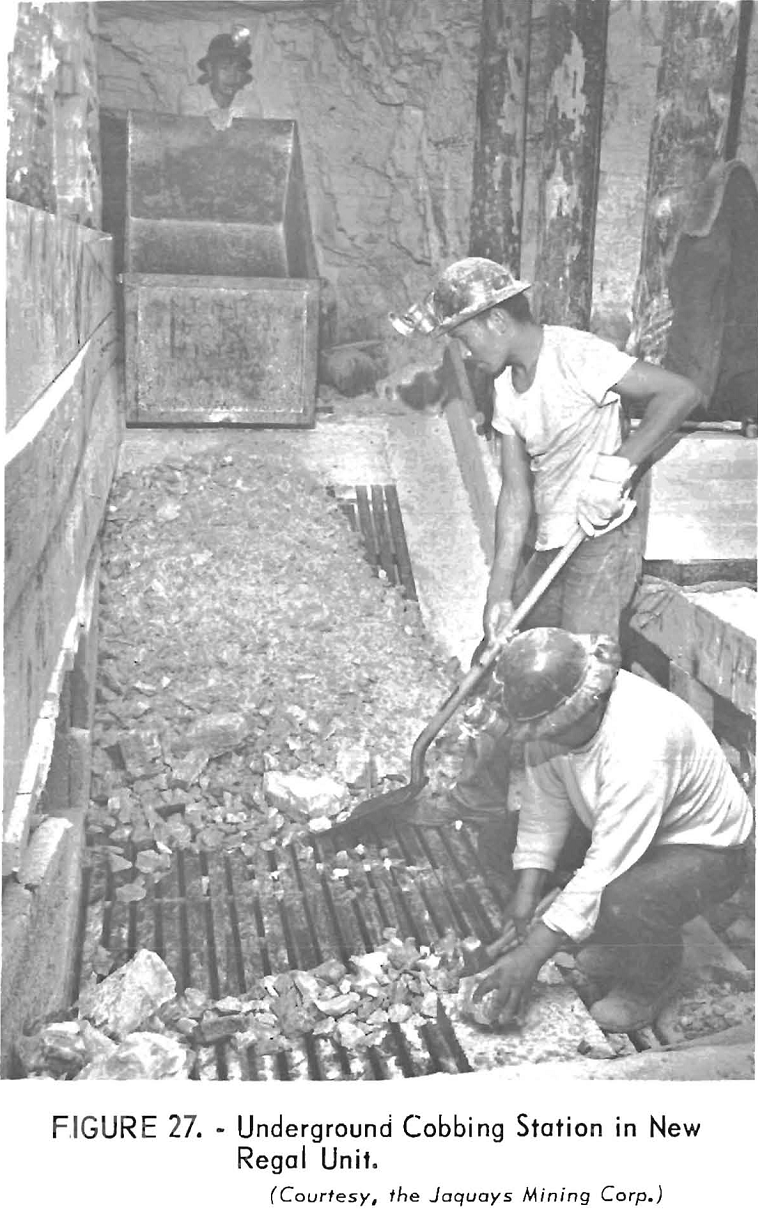
Prior to the start of the Navajo operations the cobbing facilities at the New Regal workings were underground, near the portal of the intermediate level. Adjacent to and lower than the track, two separate 3 by 12-foot grizzlies each were placed over a two-compartment raise. Ore cars were dumped onto each grizzly from a short spur track. One of these installations is shown in figure 27, Cobbed ore and resultant waste were tossed into the respective chutes to be drawn and trammed on the haulage level below. The cobbed ore (mill rock) was dumped into a bin in the portal trestle, and the waste was dumped into a chute at the end of the trestle (fig. 28). Activity has virtually ceased in these workings, and the remainder of this section deals only with the operations at the Navajo unit.
A 10-cubic-yard, 10-wheel dump truck hauls the mill rock to Globe, usually making one trip per day. An 8-cubic-yard standby truck stationed at the mine is used for ore haulage if necessary.
The two entrances to the Navajo mine permit having separate tracks for ore and waste haulage at the surface. The waste is trammed across a trestle


over the lower service road and dumped into the canyon. Fine material for road surfacing can be emptied into a truck through a trapdoor on the trestle. It is planned to place a 10-ton storage bin under the trestle.
A 2,000-gallon water tank on the hillside near the mine portal and a 2,000-gallon tank at the camp are filled when necessary from a perennial spring in the canyon by a 1-½- by 2-inch duplex, single-action pump with a gasoline motor. The water supply is augmented by a small flow piped from another spring on the roadside above.
Water for mine use is piped from the supply tank to the mine sump in the adit. Two fountains along this pipeline provide the men with drinking water. A pneumatic 3- by 2- by 3-inch duplex reciprocating pump at the sump supplies drilling water to the working faces through 1-inch pipes.
A pneumatic timber saw is used In the mine to frame timbers at the chute locations.
There is no electric power at the mine, but a small Kohler plant located at the camp furnishes light and power for the two staff houses.
Explosives are bought in lots of 10 tons (400 cases) and are trucked to the mine and stored in an isolated underground magazine. Daily requirements of explosives are issued from the magazine and carried to the working places
by a powderman. Caps and fuse are stored in a separate magazine, and no more than 1,000 caps are on hand at any one time. No explosives are stored in the mine.
Construction of the new Highway 70 mill, with its increased capacity, established the possibility of reclaiming short fiber from the upper part of the Old Regal dump. This part of the dump was built up on a bench below a vertical diabase cliff during the early mining operations, when only the hand-cobbed Nos. 1 and 2 grades of fiber were recovered.
Consequently, equipment has been placed to reclaim the dump material. A trommel, 3 feet 8 inches in diameter and 8 feet long has been constructed, lined longitudinally with 12-pound rails. The openings between the rails, which are fastened bases inward, form ¾-inch slots.
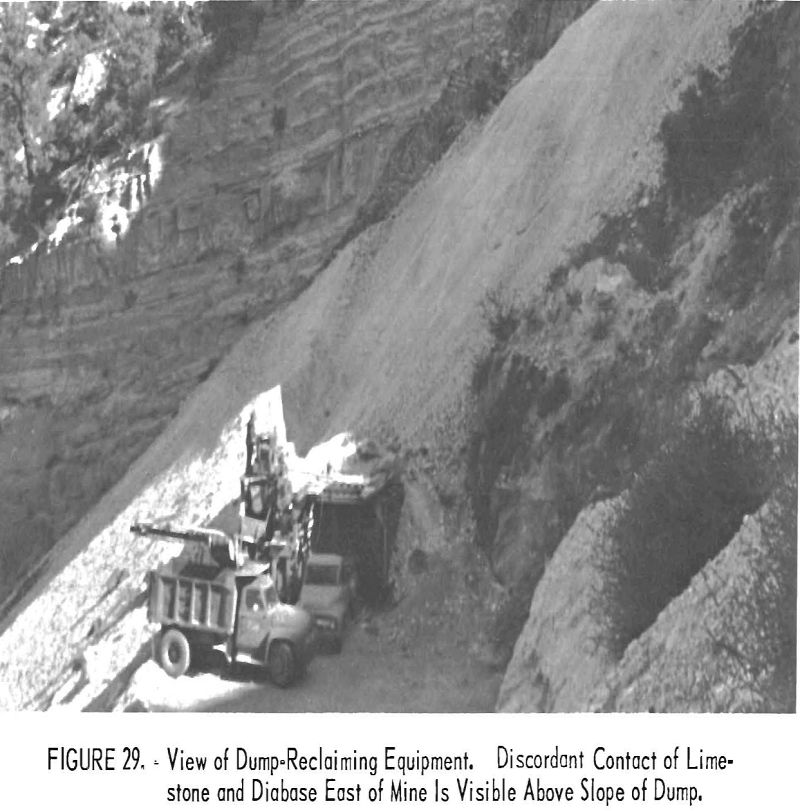
A gasoline-powered slusher with a 24-inch scraper drags the dump material to the trommel bin. Oversize material, passing through the trommel, is rejected on a transverse 17-foot by 18-inch belt conveyor. The undersize material drops onto a 30-foot by 20-inch belt conveyor, which loads an 8-cubic-yard truck (fig. 29). The trommel and waste conveyor are driven by a gasoline-powered 4-cylinder engine through a gear reduction box. The other conveyor is driven by a smaller engine.
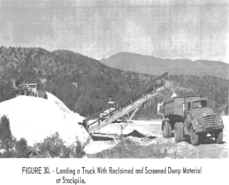
The undersize material is transported about 2 miles to a stockpile beside the main access road A bulldozer pushes the stockpiled material to a ramp, under which is a bin that feeds a 40-foot by 24-inch belt conveyor. The conveyor belt loads an end-dump semitrailer (fig. 30). The material is hauled to Globe where it is stockpiled for future treatment at the Highway 70 mill being constructed.
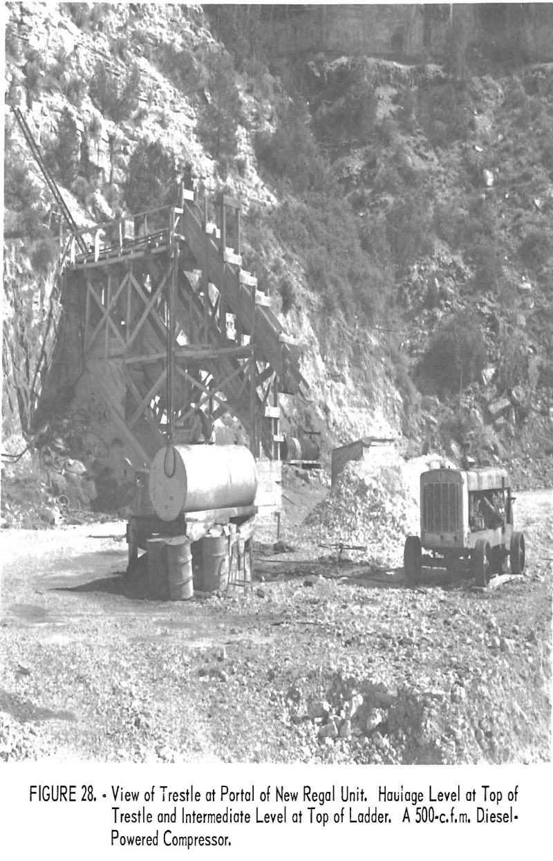
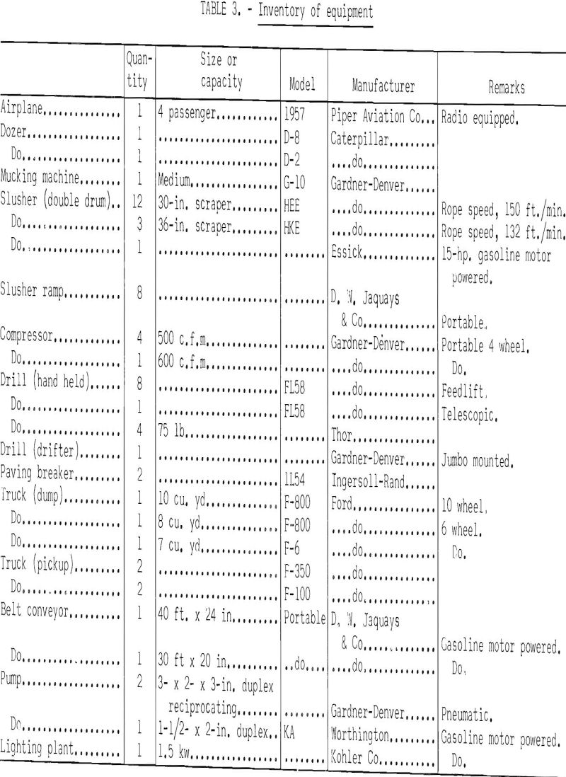
Table 3 lists the major equipment used at the Regal mine.
Percent Extraction and Production Rates
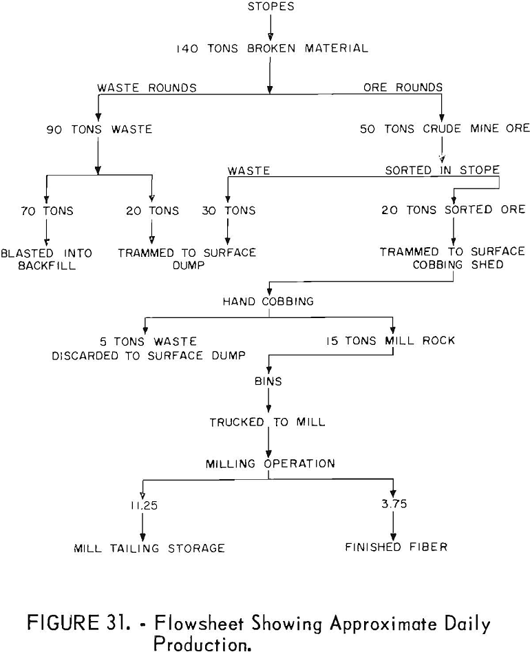
Figure 31 is a flowsheet, representing the complete cycle of average daily ore production. Fifty percent of the material broken remains in the backfill or “gob pile”, as it is termed locally. The backfilling method has been described previously.
A breakdown of production by tons per man shift during the first half of 1959 is shown in table 4.
Ventilation
Ventilation of the Regal mine presents no problem because throughout its length there are many openings to the surface. Natural flow of air through the main connecting passages is deflected by canvas brattices into the desired circulation pattern in the fringe workings.
Prior to connection with the interior workings, ventilation of the primary development drifts of the New Regal and Navajo units was accomplished by airflow from the end of the air line at the drift face.
Mine Drainage
While driving the Navajo adit, water was encountered 480 feet from the portal, where it flowed freely from the drill holes. A reservoir had been formed by a troughlike fold of the limestone bedding, some 200 feet in breadth with maximum depth of 6 feet. By the time the adit was driven across the breadth of the fold, the accumulated water had drained off. A pumping station and a sump were cut near the outside switch of the bypass station. A trench cut across the drift diverts any nine water into the sump.
Normally, this source of water for mining operations is inadequate and must be supplemented by additional water drawn from the tank at the portal.
Supervision and Labor Distribution
Under the supervision of the president-general manager, the general superintendent directs the activities of the mines and mills.
The Regal mining operation is supervised closely by the mine superintendent, who lives at the nearby camp. The mine is operated on a one-shift basis, 12 days on and 2 days off. The regular shift runs from 7 a.m. to 3.30 p.m. with a lunch break of 1 hour. A few men work on an overlapping afternoon shift, 11 a.m. to 7 p.m.
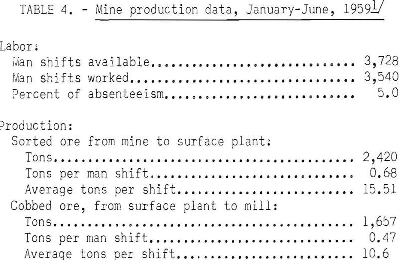
Assuming the normal 5.5 cobbing man shifts per day, each man hand-cobs 2.82 tons of stope-sorted ore to produce 1.93 tons of mill rock per shift. The waste-car counter, in use during the second quarter of this period, indicates that for each ton of hand-cobbed mill rock that was produced 2.6 tons of waste was removed from the mine.
The average number of mine employees is 24, distributed according to the following classifications:
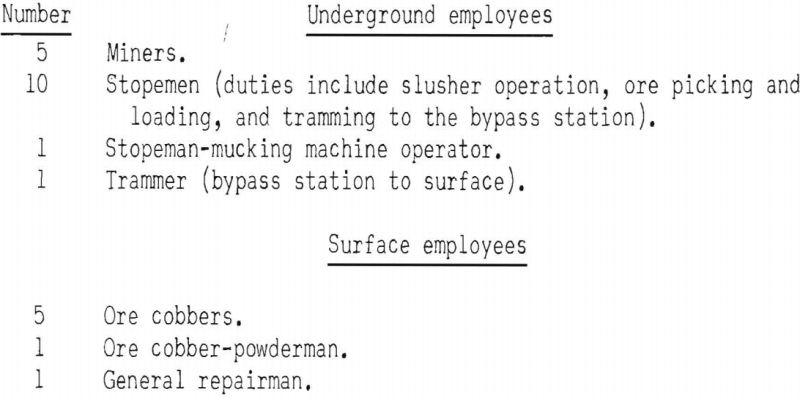
The five miners are distributed as follows:

The combination stopeman-mucking machine operator spends the first half of the shift loading out waste from the development headings, and the remainder of the shift in the stope.
Four of the cobbers are on the day shift and two are on the afternoon shift. If there is not enough ore for the afternoon cobbers to work on during their shift, they go underground and draw more from an ore chute, or recover ore from the stope. If a compressor should not be running, there is enough air remaining in the receivers and 4-inch pipeline to operate a slusher for a limited time.
Three cobbers and one stopeman work on the 2 days that the other miners have off, in order that enough mill ore will be available to keep the trucks in use the morning after the general lay-off period. The repairman, who lives at the camp, also is on duty during this weekend and acts as supervisor.
The usual duties of repairman are varied; he is the handyman, mechanic, truckdriver around the mine area, pipeman, timberman, and bulldozer operator, as required. Occasionally he hauls ore to the mill and when necessary he spreads road ballast of fine waste on the access road.
The combination ore cobber-powderman works the first half of his shift in the cobbing shed. At noon he checks with each miner to see what caps, fuse, and powder he needs. He then makes up and delivers the supplies to the miners at the working faces.
Indian labor is used exclusively and is satisfactory. Ninety percent of the labor turnover occurs within a group of 25 percent of the employees; turnover decreased in 1959. Absenteeism during the first half was 5.0 percent.
The mine workers have a camp 0.6 mile from the Navajo unit and are transported to and from work in a truck. Living accommodations in concrete block houses and frame buildings, supplemented by tent houses and house trailers, are furnished by the company. Water is available from a nearby 2,000-gallon tank, and a company truck can be utilized for hauling wood.
There are two well-constructed frame houses for use of the resident staff employees.
The operation at the Chrysotile mines is supervised by a resident mine superintendent. Because of the recent acquisition of the property (May 1, 1959), only rehabilitation work is being done by the crew of eight Indian employees.
Eight men are employed at the Globe mill, supervised by a mill foreman. The plant operates on a one-shift basis, 6 days a week.
Wage Contract Rates
The Regal mine normally has operated on a straight wage and salary basis at the prevailing rate paid in the local asbestos industry.
In 1957, a labor contract was given to expedite development of the Navajo unit, concurrently with company mining operations in the New Regal unit. The company furnished all equipment and supplies, and the contractor was paid $10.00 per foot of advance in the development haulage drifts and $8.00 per foot for raises. Cost of supplies and equipment was estimated at $10.50 per foot of advance.
The contractor was paid an additional 28.4 cents per cubic foot for slabbing rounds to widen drifts for switch turnouts and track curves and for primary stope-drift work.
Safety Practices
Supervisors of the mine are very safety conscious because both the general manager and the mine superintendent have been safety engineers. Safety suggestions of the State mine inspector are complied with at all times.
During 6 years of operation there have been no fatal accidents and very few lost-time accidents. Minor injuries can be treated at the portal, where first-aid facilities are available. Except for portal sets and chutes, virtually no timber is used, hence fire hazard is negligible.
Several of the drifts that serve for ventilation could be used for secondary exits from the mine in case of emergency. The haulage drifts that connect the three mine portals are periodically checked to insure unobstructed passage to the surface, and numerous other escape routes are available through the stopes.
The Chrysotile Mines
Aquisition of the Chrysotile mines by the Jaquays Mining Corp. has been so recent that no information about the operation is available. Considerable rehabilitation and exploratory work will be necessary before production can be attained from extensions of the old workings or from adjacent areas.
In general, the underlying diabase sill is in contact with a horizon of the lower member of the Mescal formation, approximately 40 to 60 feet below the base of the algal limestone. Asbestos-bearing zones occur in the bedding of the lower member at three constant intervals, The topmost zone is immediately under the base of the algal limestone, and two other zones occur 33 and 39 feet lower in the section. Thus the ore horizons are virtually in the same position as at the Regal mine The oscar marker bed likewise is present in much of the area.
Historical Data on Methods and Costs
The following discussion is historical in character but is included here to show operational costs at a large mine about 30 years ago.
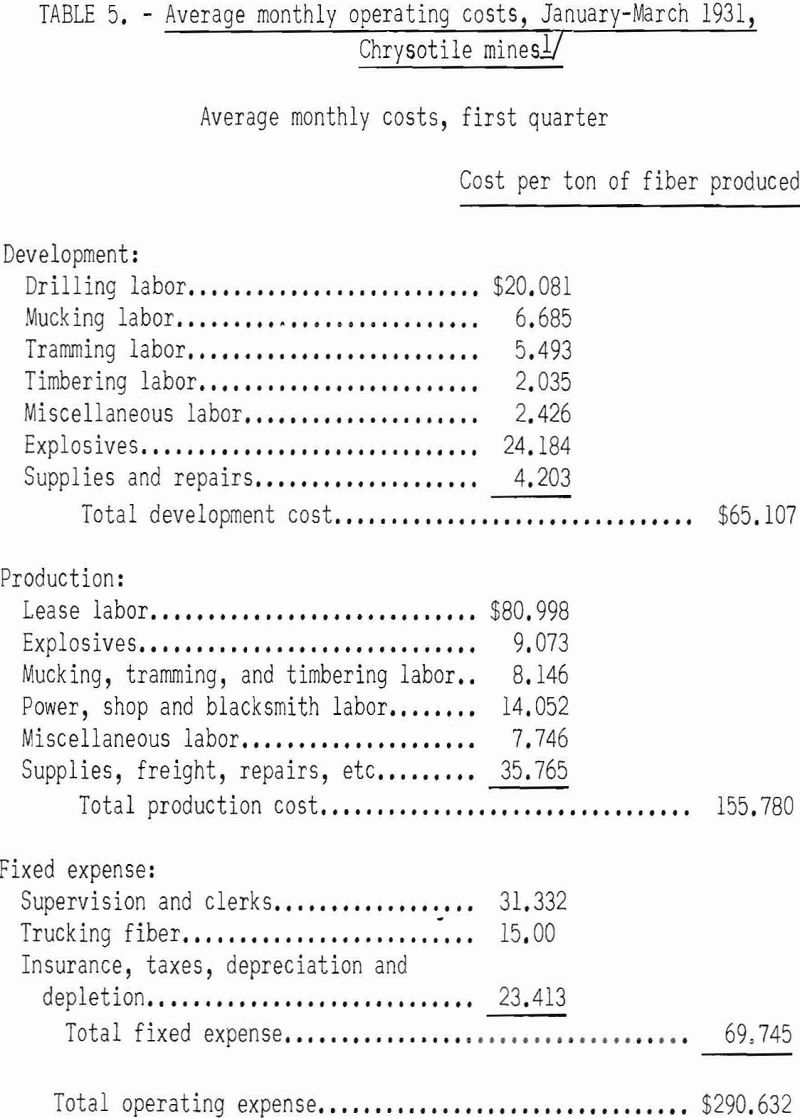
The mining operations at the Victory mine of the Arizona Asbestos Association (a Johns-Manville subsidiary after 1916) began in 1914. A small experimental mill, which had a capacity of approximately 5 tons of mill feed per 8 hours, was built. Four grades of mill fiber were produced in addition to the Nos. 1 and 2 crude grades. Because the efficiency of the mill was unsatisfactory, it was closed in 1921 and the operator reverted to hand-cobbing the two longer fiber grades. This method of recovery was continued until the operation was stopped in May 1931. Intensive production from the El Dorado mine was started early in 1929. A breakdown of the average monthly operating costs during the first quarter of 1931 is shown in table 5.
Production was accomplished under a so-called leaser system. The drifting and raising was done on company account, but the fiber was mined under the company’s direction by lessees who were furnished all equipment and supplies and were paid by the pound.
After blasting the ore round, the lessees carefully sorted the rock and hammer-cobbed and graded the crude Nos. 1 and 2 fibers. Waste in excess of that required for backfilling was moved by wheelbarrows to the nearest raise to be trammed to surface on company account.
At semimonthly intervals the cobbed fiber of each lessee was moved to the warehouse where it was inspected, check graded, and weighed. It was then resacked into 102-pound units for shipment.
During 1930, an average of 36 lessees was employed, who produced approximately 75 pounds of fiber per leaser shift. Payment at the rate of 5 and 7 cents per pound for No. 1 and No. 2 grades respectively later was raised to 7 and 10 cents.
Most of the development work was done in the diabase under the ore horizon. Development drifts, with a minimum cross section of 5 by 7 feet, were drilled with drifters mounted on the arm of a 32-inch column, using 1-¼-inch steel. A conventional 10-hole, 6-foot round was drilled using 2-¼-inch starters and finishing the hole with 1½-inch steel. The holes were loaded with 7- by 1-1/8-inch, 60 percent dynamite, using stemming. Raises of 4- by 5-foot cross section, inclined at 50°, were drilled with self-rotating stopers.
In 1930-31, the daily wage for development drillers was $4.75 and for muckers and trammers, $3.50.
During April 1931, the average advance for drifting and raising was approximately 4 and 3 feet per round, respectively. Development costs for the first 4 months of 1931 are given in table 6 for total footage of 1,744 (drifts 986.5, raises 757.5).
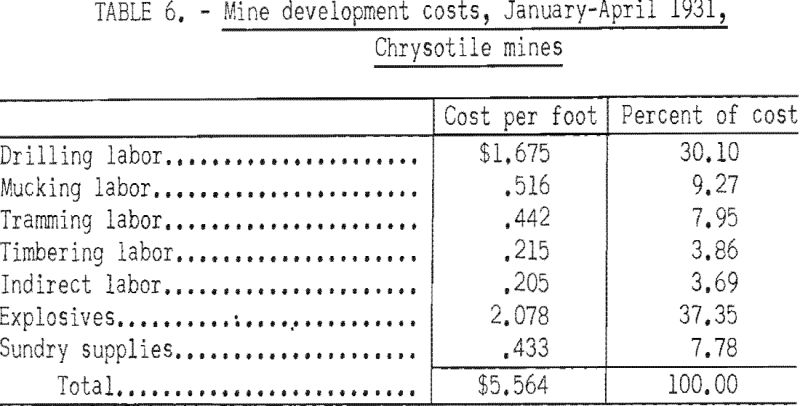
Number of tons of asbestos produced was 161.685 at a total cost of $61.05 per ton of fiber. A detailed cost check of 675 feet of drifting and 345 feet of raising indicated that raising cost was approximately 18 cents per foot more than drifting.
Tramming at the El Dorado mine was done by hand; in the Victory mine a small storage battery-type locomotive was used. Comparative tramming costs are given in table 7.
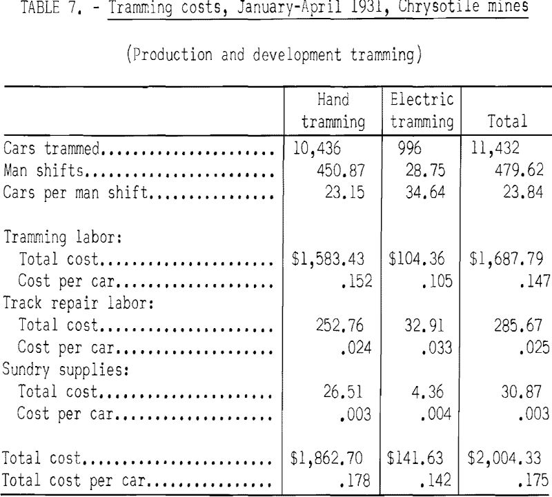
A total of 161.685 tons of asbestos was produced, and the tramming cost per ton of asbestos was $12.40.
The blacksmith shop had an electric-blown oil forge and a drill sharpener. During the first 4 months of 1931, 4,184 drills were sharpened and 261 were shanked, at a cost of 11.9 cents per drill steel.
In the powerplant were two diesel compressors with a capacity of 350 cubic feet per minute each, one semidiesel of 310-cubic foot capacity, and a 110- volt 60-cycle generator. During the 4-month period in 1931 the average cost of producing electricity and compressed air was 90.5 cents per operating hour.
To the early 1930’s access to the property from Globe was by way of Rice (now San Carlos), a distance of 64 miles on dirt and gravel road. The sacked crude asbestos was transported by truck under contract at $15.00 per ton to the railroad at Rice, a distance of 42 miles. In the 1940’s, when the Johns-Manville Products Co. resumed operations, paved U.S. Highway No. 60 had been completed and the distance to Globe had been reduced to 35 miles. The company, with their own trucks, reportedly could haul the fiber to Globe for $3.50 per ton.
Milling and Grading
Chrysotile is the fibrous form of serpentine, and in Arizona it is always associated with bands of massive serpentine. The ore-concentration process is unique in that it involves separation of a fibrous mineral from a massive form of the same mineral. Neither chemical composition nor specific gravity can therefore be used as a basis of separation. The property that makes mechanical separation possible is the fibrous structure. The gangue of the ore is serpentine and limestone. Because limestone is deleterious to the milling operation and to the ultimate uses of the fiber products, elimination of limestone in the millfeed is essential. This is done by hand-sorting and hand-cobbing at the mine.
The chrysotile asbestos of some of the Arizona deposits is soft, flexible, and of excellent quality; in others the fibers are semisoft; and in some mines the fibers are harsh. Most of the asbestos produced by the Regal mine has been of soft and semisoft quality, exhibiting high tensile strength. Fairly harsh fiber occasionally is encountered. All fiber now being mined is white and of soft quality.
Asbestos fibers fall into two main groups – crude and mill fibers. In the Regal mine, four crude grades have been established according to fiber length.

The material that is fiberized-that is, mill fiber is graded according to the Canadian classification, determined by tests made with the Canadian standard testing machine. Briefly, this machine consists of three screens (½-inch-mesh, 4-mesh, and 10-mesh) and a box for the shortest material. The four figures in the designation of the grade indicate the number of ounces fr om a total of 16 that is retained in each of the four receptacles. Thus a fiber designated 2-8-4-2 signifies that of the 16 ounces, 2 ounces remained on the top screen, 8 on the second, and 4 on the third, and 2 ounces passed through all the screens into the box.
Originally, the two longer crude grades were produced by hand-cobbing, that is, hammering off the rock adhering to fiber bundles. This method later was replaced by mechanical cobbing, which consists essentially of passing the ore through a jaw crusher and a set of rolls, then over a single-deck screening unit composed of three segments, each covered with screen of proper mesh size to produce the four crude grades. The flow of material over the screen was accomplished by longitudinal shaking or by bumping.
The crude asbestos produced by this separation method retains more or less of the natural solid form in which it occurs in the veins. The spinning-grade products, Nos. 1 and 2 lengths, require more processing to separate and to open the fibers. This processing is done at the textile manufacturing plants.
In order to market the shorter grades of Arizona fiber more complex mills, designed to recover and process these grades further, gradually evolved. Recrushing in stages is followed by screening and air separation of the fiber from the rock.
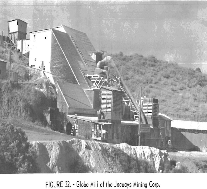
At the Jaquays Mining Corp.’s Globe mill (fig. 32), the reject from the cruding section is fed to hammer mills where the shorts are fiberized or opened into a fluffy form. The enclosing rock, mostly brittle serpentine, pulverizes easily and is separated from the fiberized asbestos by fine-mesh shaking screens. The fiberized material is then air lifted from the screens and transferred as a finished product to the bagging room.
The fineness of the final fiberized product can be controlled by adjusting the fineness of the mill rock that is fed to the hammer mill, or by adjusting the retention period in the mill. These adjustments are made in order to furnish the particular grade desired by various customers.
The flowsheet of the Globe mill is shown in figure 33. The capacity of the plant for producing crude grades is 1-½ to 2 tons of mill rock per hour. The capacity of the fiberization equipment depends upon the grade of the product desired. For instance, the triple A (a blended grade) can be produced at
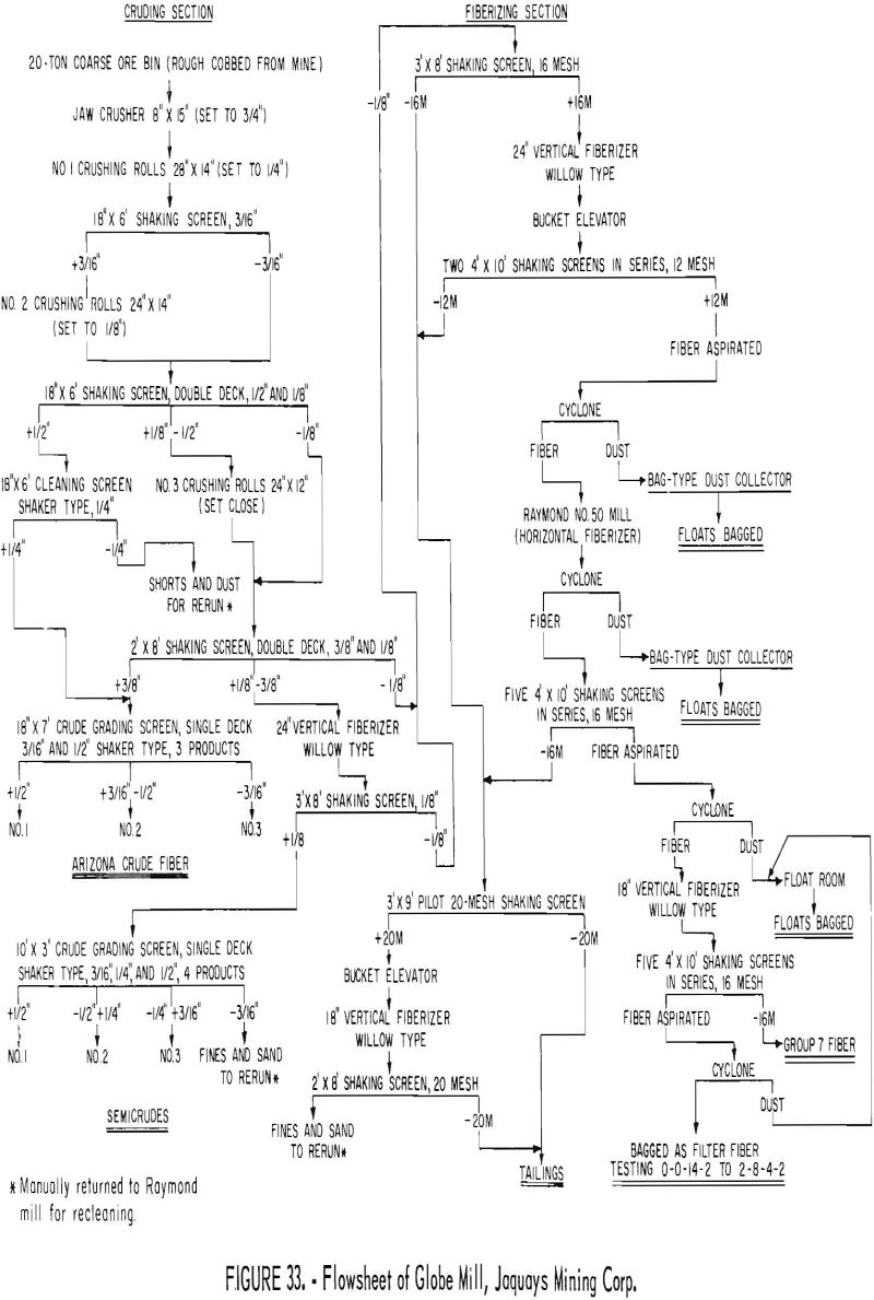
the rate of 1 ton per day; other filter fibers can be processed at the rate of 2 or 3 tons per day. One 8-hour shift per day suffices for efficient and balanced operation of both the mine and mill.
Each piece of equipment in the mill is driven by an individual 220-volt motor, ranging in size from 1 to 80 horsepower. The combined horsepower rating of the various motors totals 293, but the electrical consumption records indicate that an average of only 180 horsepower of electrical energy is consumed in the milling operations.
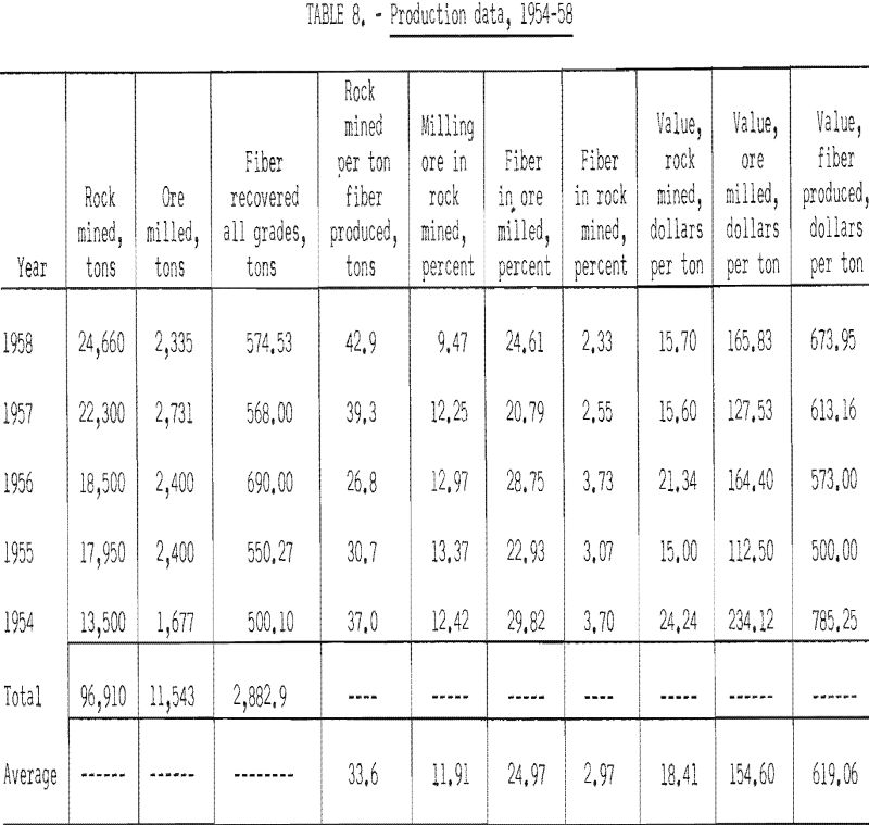
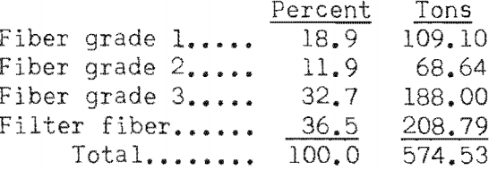
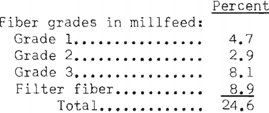
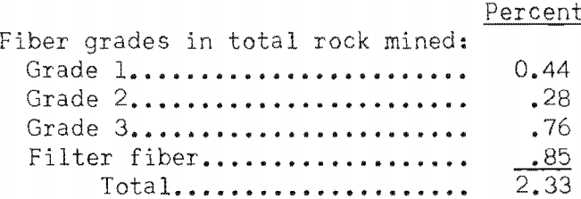
The production rate of the mine and mill for the 5-year period 1954-58 is shown in table 8. Also shown for 1958 are the percentages of crude grades and filter fiber in the total asbestos production, in the mill feed, and in the total rock mined.
During the period of 1952 through 1958 the General Services Administration, acting for the Defense Minerals Procurement Agency, authorized the establishment of an asbestos-purchasing depot at Globe for procuring the strategic grades of fiber. The Government purchase prices for the three crude grades were as follows: No. 1, $1,500; No. 2, $900; and No. 3, $400.
The purchase prices of the various grades of filter fiber are determined by negotiation between the buyer and seller, as are those of the crude grades, since the close of the Government purchase depot. The various fiber products are purchased by the spinning, wine, brewing, edible oils, electrical, and chemical industries.
The mill tailings are marketable to a west coast firm that processes the tailings into stucco material, water paint base, etc.
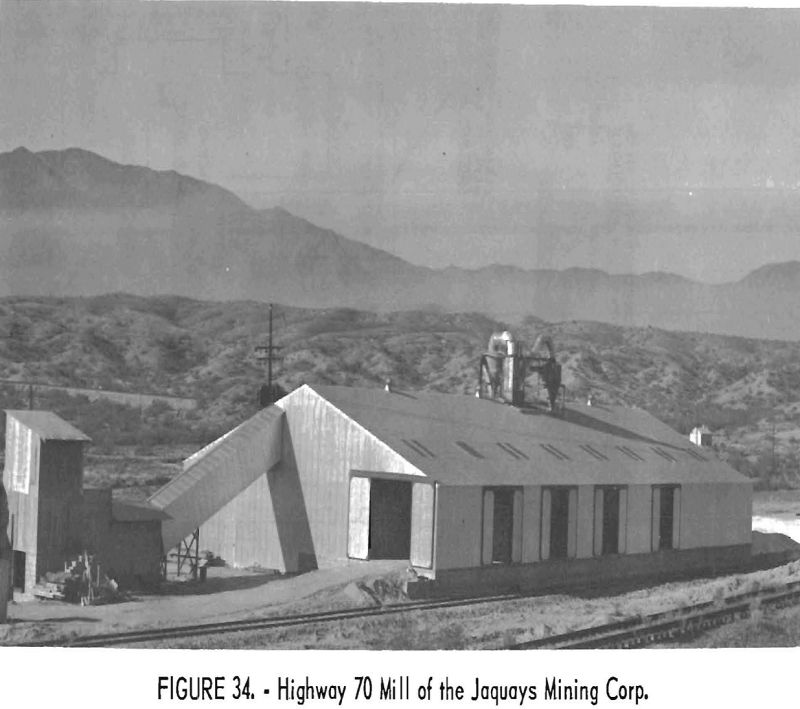
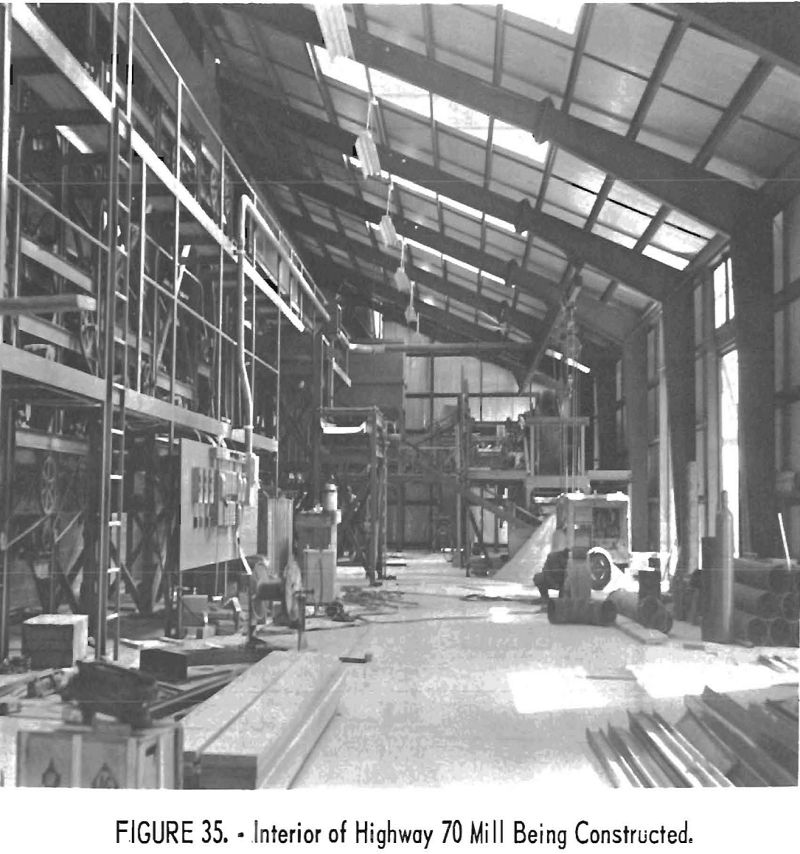
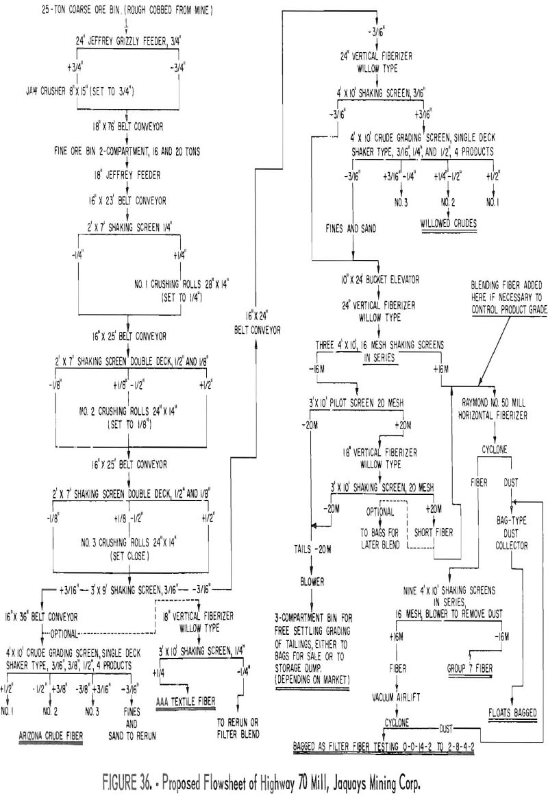
The Highway 70 mill, in construction in mid-1959 (fig. 34), will have a somewhat different flowsheet than the Globe mill, which it will replace. Figure 35 shows the construction phase of part of the mill. At the left is a bank of screens, beyond which is part of the cruding section. Its hourly production rate is expected to be double that of the Globe mill. The proposed flowsheet, shown in figure 36, provides for the use of more screens for elimination of dust from the fiber and for closer sizing of the products.
The company plans to install an acid-treatment unit in the new mill in order to eliminate calcium from its various grades of filter fiber. The unit is to be designed to handle about 2 tons of filter fiber a day.
Arizona is the only domestic source of natural low-iron chrysotile, which has great importance for electric insulation products, such as electrical tapes and cable covers. An iron analysis was made on several milled fiber samples that were available to the author. In the following tabulation, the Fe2O3 represents Fe dissolved by boiling HCl. The FeO is the Fe remaining in the asbestos after this treatment. Magnetic iron content was not determined.
The breakdown of the grades of fiber produced in 1958 follows:

The Arizona sample was from the Regal mine; the low iron content is typical of the fiber from mines in the district.
Cost for Year of 1957
The cost breakdown on a percentage basis for the year 1957 was:

