Table of Contents
Flotation circuit designs are also being influenced by operating philosophies possible with computer automation. It has been pointed out that flotation flowsheets tend to be simplified through use of online control. Logical control capability can reduce the necessity for recirculating streams, bringing circuits into open circuit mode with little or no metallurgical losses.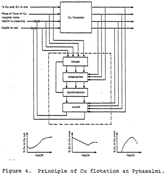
Control techniques for automation of flotation circuits, in sequence of progressively greater sophistication, are
- feedforward and feedback reagent control
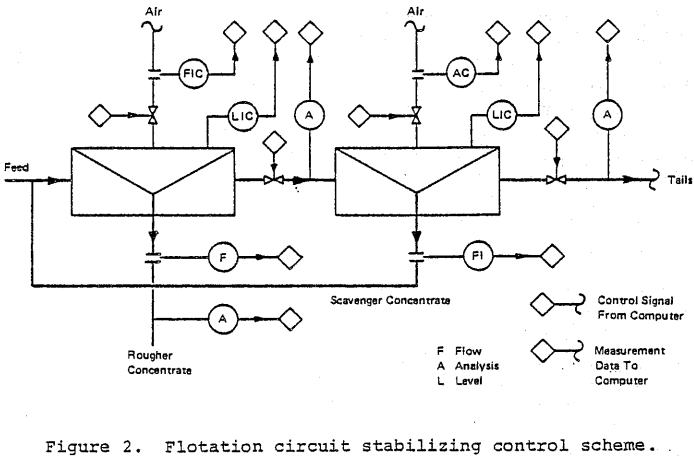
- flotation circuit stabilization, to control the tendency for circulating streams to fluctuate in volume
- control of flotation variables according to criteria established through mathematical models of flotation circuits
- optimizing control, in determining the most favorable economic conditions of flotation circuit operation.
Most flotation control systems in practice employ control methods in various combinations of the above. Applications at several representative concentrators are summarized in case historied following a general description of control procedures.
An effective strategy for online computer control is to first apply stabilizing control for flotation circuit operation. Stabilization is achieved by selecting feedforward and feedback loops to act in response to disturbances arising because of changing mineralogy and mechanical, influences. Extension of control through more complex schemes can follow when stabilizing control is established. Development of mathematical models to increase the scope of control is usually specific to conditions of application, as compared to stabilizing control based on more general principles.
FLOTATION CONTROL TECHNIQUES
The control system function is to achieve prescribed objectives for operation of the circuit while the influence of various process disturbances cause deviations from the objectives. Mineral flotation characteristics are changing because of the disturbances occuring as a result of natural processes in addition to flotation effects influenced by processing ore through grinding. Many disturbances to the flotation circuit can be measured, but these variables are generally not possible to manipulate directly to offset their effects on flotation performance. Typical measured disturbances are
- ore feed rate
- feed slurry pulp density
- assay of feed
- particle size distribution of feed slurry
When an integrated control system for concentrator operation can account for these variables, they no longer are considered disturbances but may assume the role of controlled variables.
Un-measurable disturbances to flotation characteristics also enter consideration under varied conditions of ore preparation, reagent qualities, and preconditioning. Examples are
- flotation rates as influenced by mineralogical composition
- mechanical condition of the cells in terms of aeration efficiency of the mechanisms, froth overflow-weirs, and pulp distribution effects
- characteristics of the minerals in terms of grain size, sliming or other mechanical blocking factors, and surface conditions as may result from oxidation and chemical poisoning
- the degree of mineral liberation during grinding.
Control Flotation by Feed-forward
Control strategies based on feed-forward imply regulation of control variables derived from the measurement of significant variables in the ore feed. Representative measurements are
- flotation feed ore tonnage rates
- assays of flotation feed
- properties of flotation feed including pH, conductivity, and redox potential.
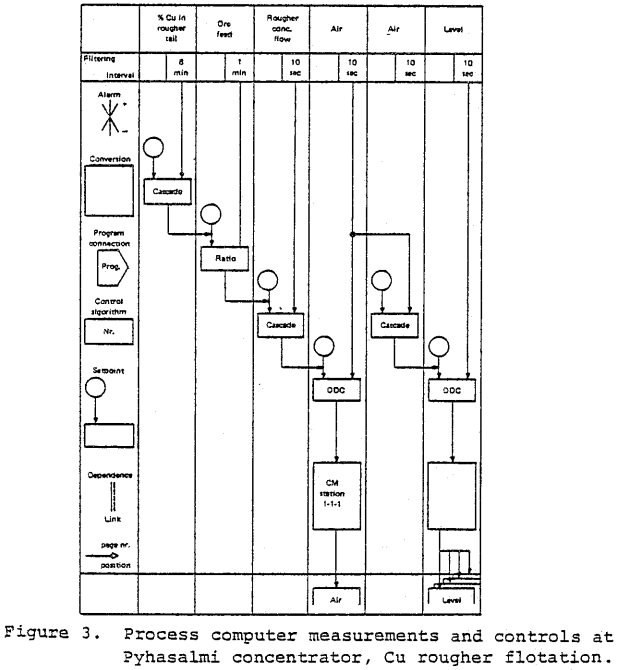
Feedforward control in simplest form centers on regulating reagent feed rates, based on a linear ratio to assays or tonnage measurements. Feedforward control in a more developed mode can employ mathematical models of circuit operation linking several process parameters.
Feedback Control for Stabilising Circuit Operation
Although feed forward control provides a degree of stability in circuit operation, stabilization is more readily attained by use of feedback as well as feed forward methods. Three control functions fundamental to stabilizing flotation circuits are
- adjusting ore feed tonnage to maintain an objective tails assay while ore feed assays are changing
- maintaining stability of concentrate flows as periodic cyclic changes in circulating loads arise in closed circuit flotation because of ore grade changes
- balancing proportions of circulating flows to meet control objectives of recovery and grade as variations in flows are propagated as result of ore feed grade changes and other disturbances.
Flotation control to obtain stability of circulating loads imparts a discipline to circuit operation by comparison to manual control. Operating personnel, given the opportunity, tend to adjust circuit operation according to individual. initiative. This practice frequently causes circulating loads to vary shift-to-shift according to the individual operator’s practice. Unmanaged variations in circulating streams lead to metallurgical losses as loads are generated and dumped from one shift to the next.
Stabilized cell production is achieved by regulating cell overflow products through control of the froth level (height of froth on the pulp), or controlling air flow, as well as combining the two control modes when practical. Measurements for feedback control are cell overlow products, cell levels, and air flows, as well as tails and concentrate assays.
Regulation of reagent rates by feedback control is carried out, for example, by control of collector based on tails assay. Similarly, control of frother feed rate can be made from the measurement of concentrate flow. However, response characteristics of reagent feedback control loops tend to be irregular due to influences of such disturbances as mineral flotation rates which, usually are poorly predicted.
Controlling Circulating Loads in Flotation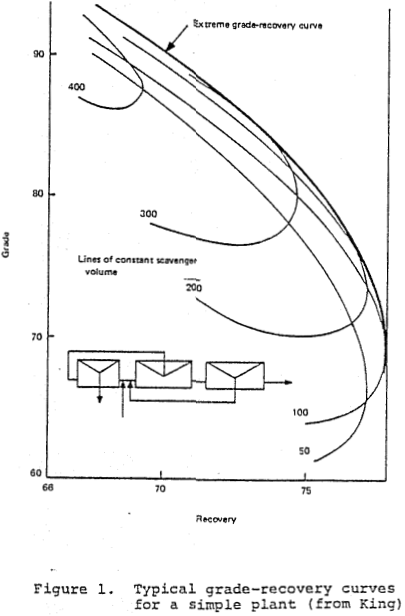
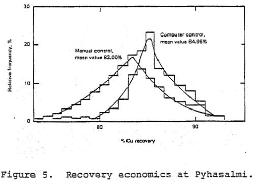
Controlling flotation by stabilizing circulating loads can greatly influence economics of operation. Simulation studies of circuit operation illustrate the influence of circulation in the cell bank on metallurgical performance.
Noting parameters of circulation rates influencing the grade recovery curves, it is seen that a feedback control system provides an opportunity to maintain cell bank operation at circulation rates suitable to each case of mineral flotation characteristics. The operating setpoint for aeration can be limited by the constraint of maximum aeration rate considering overall air blower capacity available for the flotation system. Typically, the volumetric air rate used is the maximum, as limited by blower capacity at any instant of time. It is necessary to monitor total air flow demand to insure the available air is distributed on a controlled basis to each cell bank.
Cell level can be adjusted to increase or decrease pulp overflow, thus performing the function of aeration control. But the dynamics of the control loop are often unfavorable because of the time lags in response and cell level changes imposed through control propagate within a flotation circuit consisting of a series of cell banks. It is occasionally necessary to employ level control when overflow products is a highly stable froth. Reliable flow measurement with a magnetic flow meter is impractical if the concentrate is frothy, and level control is the only practical control method then available.
Stability control is dependent on measuring circulating loads. Mass flow of solids is the variable of direct interest, and volumetric flow is suitable if per cent solids is relatively constant. Mass flow determination requires, in addition to flow, a density measurement. Reliable density and volumetric flow measurements to determine mass flow makes necessary the increased attention to maintain and calibrate two sensors, instead of only one for volumetric flow alone. Considering the potential for compounded error, the control requirement has been shown to be adequately met by volumetric measurement alone.
Selection of a Computer Control System
Several factors led to the decision to start with computer control of the flotation process instead of the grinding circuits. These were –
- The complex nature of the flotation process.
- A more thorough understanding of the flotation process.
- Greater ease of installation of process control equipment for flotation control.
- Unreliability of particle size measurement, which is the most important control variable for Brunswick’s grinding circuits.
- Existence of an on-stream x-ray analyser since 1973.
It was believed that even the simplest form of flotation control would give an improvement in flotation results. Reductions in reagent consumptions of 10% and a Pb recovery increase of 1% were therefore forecast. The No.12 Cu-Pb circuit was selected as the first section of the flotation plant to be placed under computer control.
The Proscon 103/105 process control system from Outokumpu Oy was selected for the following reasons –
- Outokumpu’s expertise with computer control equipment in the mineral industry.
- The ease and relative speed with which the controls could be expanded to the rest of the plant, (i.e., crushing, grinding).
- The ease with which metallurgical staff, having minimum programming experience or knowledge of process control theory could implement their own control loops.
The Proscon system seemed to meet these demands. Another factor influencing the decision was Brunswick’s experience in dealing with Outokumpu since the acquisition of the courier 300 x-ray analyser,
On-Stream X-Ray Analysis
One of the most important requirements of any type of flotation control is the frequent availability of reasonably accurate assays of critical process streams. A 28 stream Courier 300 x-ray analyser was installed in 1973 to meet this requirement. The present unit analyses sampled streams from the No.12 CuPb and Zn circuits. Twelve of these streams are withdrawn from the Cu Pb circuit, six for each line.
Primary sampling is performed with sample thiefs on pump discharges or with 5 cm air activated Weldon diaphragm pumps at tail box locations. Horizontally mounted Outokumpu slot cutters sample concentrate streams from process piping. Approximately 200 liters/min. of primary sample are withdrawn.
The 28 process streams are pumped to 14 secondary samplers mounted behind a centrally located analyzer room. Pairs of adjacent primary samples are multiplexed between each sampler, which withdraws 20 liters/min. into the sample cell. All samples are returned to the flotation circuit.
Each sample is analyzed by a moving x-ray head for twenty, seconds. Concentrations of Fe, Cu, Zn, Pb and slurry density, are calculated by the software. The second sample is introduced into the secondary sampler when a sample measurement cycle has been completed and the x-ray head moves on to the next sample cell. This procedure therefore eliminates the need of flushing each sample cell with water.
A Digital Equipment Corporation PDP11-34 computer containing 32 k of core memory is used for computation of elemental analysis and co-ordination of hardware activity. In addition to slurry density, calculation of element contents can also take into account interelemental effects. The form of the equation is as follows.

Each “q” parameter is determined from sets of calibration data using a multivariable linear regression program. The accuracy of each model is checked three times a week and appropriate changes to the intercept “qo” can be easily made.
Earlier versions of the Courier 300 software did not consider interelement effects, but only that of the element in question and slurry density. This earlier version gave unreliable estimates of low Pb content (i.e. 1-3% Pb) slurries. Recent calibrations using the interelement model have shown that the Pb content of these streams can be more accurately estimated when only Pb and Zn pulses are considered. The effects of slurry density for these streams are non-existant because of the very slight variation in slurry densities, a requirement of the flotation process. Significant deviations of the estimates can still be experienced. These deviations are related to major variations in grind, a variable not explicitly considered in the calibration model.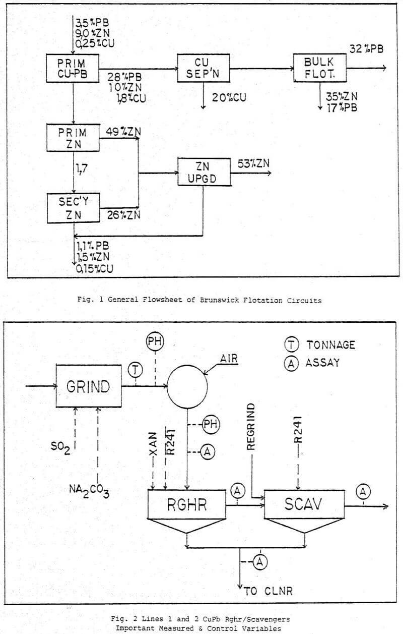
One operator per shift is given the responsibility of ensuring that all samplers are working properly and that samples are flowing freely. The availability of the system is 95%. Major causes for slurry downtime have been mechanical breakdowns to primary sample transport pumps of to pumps returning the samples to the flotation process.
Analyzer results are displayed every 10 minutes on a printer located in the flotation control room. Measurement data is transferred to the Proscon 103 computer on an interrupt basis, upon completion of every sample measurement. Measurements in an alarm state (i.e., low slurry density, sample cell plugged, etc.) are not accepted by the Proscon.
