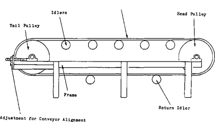
 Idlers: Due to the efforts of the Conveyor Equipment Manufacturers Association, the basic idler elements—idler roll wall thickness, bearing sizes and shaft sizes—have been standardized into classes. There is also a substantial dimensional commonality as well.
Belting: Again, the rubber manufacturers have standardized, either by agreement through industry associations, or by following the leader and providing competition.
Smaller belt conveyors within the plant will be overbelted to match the belts used on larger conveyors and thus reduce the variations that must be stocked for emergency replacement.
Pulleys: The most commonly used conveyor pulley is the standard welded steel pulley, which is manufactured in a wide range of sizes. The “American Standard Welded Steel Conveyor Pulley” standard applies to a certain pulley construction, its load rating, and establishes dimensional guidelines.
Accessories: Zero-speed switches and other safety devices, scrapers, plows, and guards have been standardized by our company and most other engineering organizations. They are available also as purchased elements from equipment suppliers.
Idler stringers, chutes and skirting: As with accessories, we and most other engineering companies have standard designs that define the construction of these elements and minimize the need for additional design on each project.
As noted in the previous section, many of the major conveyor components are already standardized by industry.
The following items are left for the standardization program:
- Drives.
- Pulley assemblies including shafts and bearings.
- Structural supports for terminals, take-ups and intermediate sections.
This does not include major structures such as long-span trusses, truss galleries, tube galleries or support bents. These are semi-standardized as part of our ongoing structural development and are continually being refined.
Elements That Cannot Be Standardized
- Drives: We could not find sufficient cost justification, or a rational commonality pattern to include drives in our standardization program. However, we continue to look at this possibility.
- Conveyors Under 24 Inches in Width: According to our experience, these are not sufficiently used by the mining industry to make any standardization worthwhile.
- Conveyor Over 60 Inches in Width: Originally, we felt these larger belts deserved the critical and careful analysis that results from individual design, and they were not included. Later experience, however, has shown the advantage of some standardization of these larger conveyors and they are now being included in our programs.
By employing the standards, the designer uses the maximum belt tension and selected belt carcass as the starting point or criterion. Charts and tables then give him optimum head pulley and bearing sizes, and frame and pulley geometry for any given angle of conveyor inclination, as well as bearing center dimensions. Once the head pulley is sized, all other pulleys in the conveyor are derived from the following relationships :
- Drive snub pulley—Two diameters smaller than drive pulley.
- Bend pulley—Two diameters smaller than drive pulley.
- Tail pulley—One diameter smaller than drive pulley.
- Take-up pulley—One diameter smaller than drive pulley.
- Tail snub pulley—Two or three diameters smaller than drive pulley.
Our charts and tables for pulley terminals were developed to satisfy the following:
- Pulley sizes are based on allowable belt ply and carcass stress so as not to overstress the belt carcass.
- The maximum allowable resultant force assumed for each size pulley shaft is the vector addition of T1, T2, plus the weight of the pulley. This T1 force determines the belt selection parameter.
- Bearing centers for each shaft size were established to provide adequate belt pulley widths and safe allowances for the belt to steel clearances.
- Pulley support steel framing members were sized to the expected pulley forces.
- The geometry of the pulley terminals was pre-established to provide for proper clearance and, belt alignments for the belt return.
- For inclined belts, those from level to 17 degrees, the belt geometry and steel clearances were precalculated and tabulated.

Do’s and Don’t’s on Belt Conveyor Maintenance
Belt conveying is a method of transportation that requires proper servicing and maintenance if completely economical results are to be obtained from the system.
When a conveyor system is installed, the manufacturers of the equipment and belt will furnish adequate operating and maintenance information and bulletins or drawings, listing component parts, accessories, etc. Too often, however, this information is filed in the purchasing or engineering offices and the maintenance men are left with nothing of real value to help them with their work. One belt man properly equipped can patrol a belt line of 1½ to 2 miles to lubricate idlers and drives, maintain belt and conveyor frame alignment, detect sticking idlers, and maintain an unobstructed right-of-way.

Where a long or steeply inclined belt is installed, with design data indicating the need for a 75-hp motor, it is not playing safe to install a 150-hp drive and motor. It is the most unsafe thing to do, as this


overload starting power will certainly not help the belt. A high tension belt should not be started with across-the-line control.
Only use dual pulley drives or tandem pulley drives where they are required to reduce belt tension and thereby permit the use of a more economical belt carcass. Dual or tandem pulley drives should never be used without being properly lagged, preferably with grooved rubber lagging. If there is a wet or frosty condition, the grooved lagging will definitely help eliminate belt slippage at the drive.

