
The Speed Reducer eliminates unnecessary transmission equipment, thus providing compact drives, and assures positive performance. It is made with speed reduction ratios up to 4,000 to 1 and with right angle (vertical or horizontal), or parallel shafts for either light or heavy duty. The information which follows gives applications and other pertinent data on the various general types.
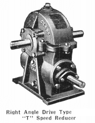
Right Angle Drive Type “T” Speed Reducers are manufactured with reduction ratios ranging from 10 to 1 up to 100 to 1. These units are equipped with hardened steel, ground thread worms and phosphor-bronze gears, producing the smoothest possible transmission contact. The worm is located on the bottom or underneath the worm gear. Timken bearings are standard equipment on all these units. Five sizes are available. Special shaft extensions can be furnished.
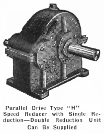
Parallel Drive Type “H” Speed Reducers (for single reduction with wide faced helical gears) are designed for continuous duty and long life. Reduction ratios of from 3 to 1 up to 12 to 1 are available with these units, and double reduction with this type, i.e., type “HK,” gives ratios from 10 to 1 up to 84 to 1. No dirt can interfere with the smooth operation of these units. Each part is self-lubricated. Slight end thrust is absorbed by Timken bearings which are used throughout to ensure continuous, efficient operation.
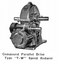
Compound Parallel Drive Type “T-W” Speed Reducers are equipped with Timken bearings and are primarily for low speed applications requiring large turning effort. Speed ratios of from 73 to 1 up to 4,000 to 1 are available with these units. All units are equipped with two sets of phosphor-bronze worm gears and hardened steel worms which have their threads ground and polished.
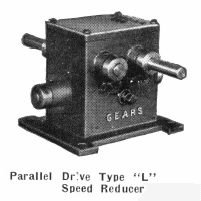
Parallel Drive Types “LA,” “LB,” and “LD” Speed Reducers have two worm and gear reductions, making a light drive unit of high ratio. Type “LA” will give reduction ratios from 25 to 1 up to 900 to 1, type “LB” ratios are from 16 to 1 up to 900 to 1, and type “LD” ratios range from 37 to 1 up to 1,740 to 1. These units are designed for the operation of light revolving apparatus.
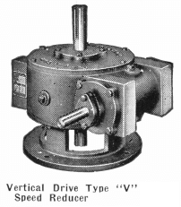
Vertical Drive Type “V” Speed Reducers have single reduction gears which are identical with those used in Right Angle Drive Type “T” Speed Reducers. They are available in the same speed reduction ratios and are for the same general type of use. These units are Timken bearing equipped throughout and give smoothest possible transmission contact and reduction.
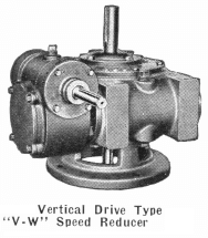
Vertical Drive Type “V-W” Speed Reducers have compound reduction and are designed primarily for low speed applications requiring high torque. Speed reduction ratios for these units range from 146 to 1 up to 3,200 to 1. Each unit is Timken bearing equipped throughout for greatest efficiency and durability.
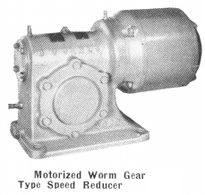
Motorized Speed Reducers are available in three types:
- planetary gear type with the drive parallel to the motor shaft,
- worm gear type with drive perpendicular to the motor shaft in a horizontal plane, and
- spiral bevel gear type with drive perpendicular to the motor shaft in a vertical plane.
The worms are of case hardened, chrome-nickel steel; gears of alloy bronze; and over-sized gear shafts are ground alloy steel. A perfect oil seal prevents oil from traveling along the shaft and thus onto the motor windings where severe damage would be the result.
A wide selection of horsepowers are available in Motorized Speed Reducers. Fractional horsepowers available are 1/6, ¼, 1/3, ½ and ¾ with output speeds varying from 680 R.P.M. to as low as 10 R.P.M. These units are obtainable for operation on practically all variations of current characteristics. Integral horsepower units are available from 1 up to and including 50 H.P. Output speeds range from 780 R.P.M. to as low as 13.5 R.P.M.
The types and sizes of Speed Reducers and Motorized Speed Reducers available are too numerous to list here, but recommendations for the proper unit to meet your specific requirements will gladly be made. Data to enable our engineers to make the correct selection of a unit to meet your needs should include: for speed reducers— speed reduction ratio desired, horsepower and speed of prime mover (if the latter data is not available, substitute torque in inch-pounds and output speed desired), and class of service, i.e., continuous or intermittent and with or without shock load; for motorized speed reducers—data provided should be the same as that required above plus as complete data as is available on current characteristics.
Source: This article is a reproduction of an excerpt of “In the Public Domain” documents held in 911Metallurgy Corp’s private library.