The Alimak Raise Method, using the Alimak Climber, has proven to be a new, fast, economical method of driving raises at the Iron King Branch of Shattuck Denn Mining Corporation, Humboldt, Arizona.
In order to fully understand the advantages of the Alimak Raise Climber, it is necessary first to describe the basic machine; second, a complete cycle of a raise round; and third, the comparative speed and economy afforded the Iron King operation by using this new method of raise driving:
The raise climber consists of a drilling platform that is raised and lowered by two 6.2 HP compressed air motors that drive, through roller chains and sprockets, three worm gears connected in series. These worm gears drive pinions which grip the guide rail rack. The worm gears are fitted with spring-loaded couplings so that a small rock or grit in the rack is passed over without disturbing the mesh between the rack and the other pinions.
The rack is incorporated into the right side of the guide rail just behind the front steel plate. The rack consists of 19mm diameter pins set 27 pins to the meter. Between each pin a hole is cut in the front plate to facilitate cleaning.
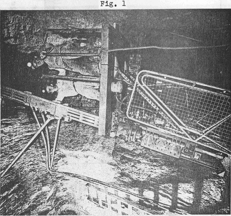
The standard guide rail is made up of 4 steel pipes 1-¼” in diameter banded to the front steel plate and to rear anchor brackets, and weighs 27 pounds per foot. The guide rail comes in lengths of 20 inches, 3 ft. 3 inches, and 6 ft. 7 inches. The four pipes are grooved at the end plates and “O” ring seals are placed between the sections of guide rail, sealing the pipe connections. The guide rail forms a track which, when rock-bolted to the raise wall, forms a means of lifting the drilling platform to the desired height. (See Fig. 1)
The support structure for the drilling platform consists of a heavy steel frame with four sets of guide rollers that fit around the front section of the guide rail track. From the top of this vertical support structure a drilling platform is hinged and supported by two adjustable legs. These legs can be set so the platform is level regardless of the angle of the guide rail track. The track angle can be set from vertical to 55 degrees.
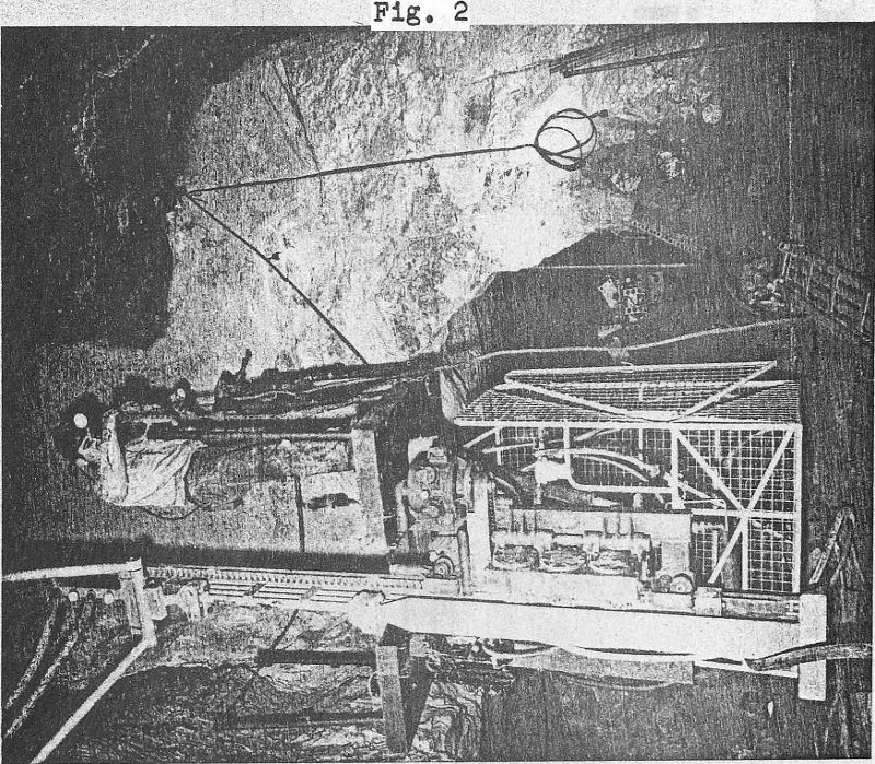
If you will look at (Fig. 2) you will see the man cage that is attached below the platform. The cage will accommodate two men, is entirely enclosed with wire mesh, and has a gate door on the side. This cage is the operating center for raising and lowering the Climber. The operating handle and safety brakes are located within the compartment and this is a very safe position for the men during the raising and lowering operation as the heavy drilling platform acts as over-head protection. Within the drilling platform, and directly above the cage, is a hinged section that can be pushed up and forms a passage from the cage to, the drilling platform.
Located within the cage compartment is the air and water manifold. The manifold has connections for the drilling machines and for the supply. The oilers are incorporated into the manifold and feed oil to the raising and lowering air motors or to the air drills. The oilers are filled each shift, or oftener, from a ten gallon oil reservoir that actually is a hollow section within the drilling platform. A small hose is used to fill the oilers. It should be noted that, one of the main modifications made to the machine by the Iron-King Shops was the rearrangement of the oiling system. Our miners were not familiar with the Swedish Oilers and did not find them easy to adjust, so a large oil-reservoir was placed in the center of the manifold, balanced with air pressure, and oil fed through; Ingersoll-Rand oil feeding valves to all machine connections. This arrangement has been very satisfactory.
Although Alimaks now being delivered in the United States are equipped with Standard U. S. pipe thread nipples and couplings, our first machine was supplied with Swedish threaded pips connections. They use a straight threaded pipe that requires wicking, so the other modification changed all nipples and couplings to those with Standard American tapered pipe threads.
One other basic construction feature of the drilling platform should be noted: The outer two feet of the platform is hinged so it can be raised during the time men are barring down the back to allow material to pass the Climber’s platform and fall to the bottom of the raise.
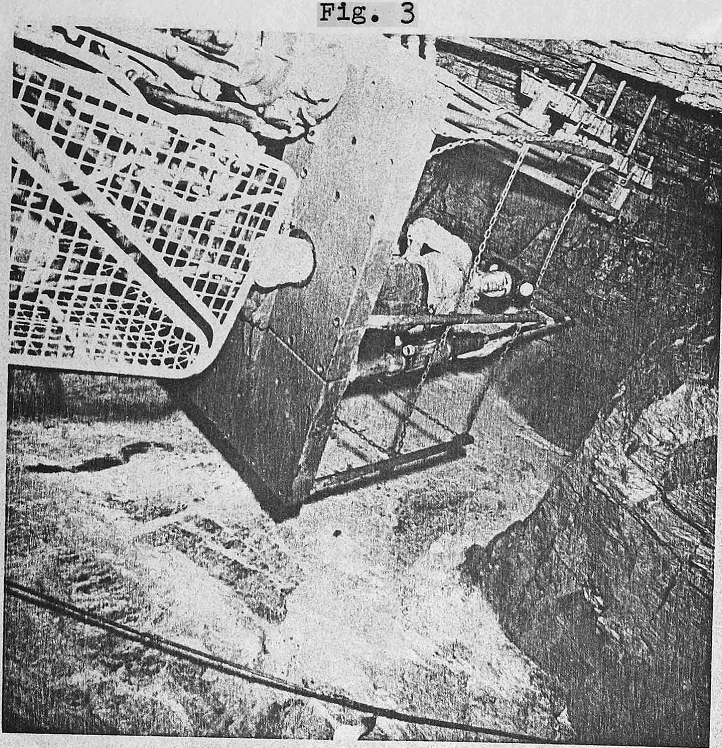
Additional features of the machine include a drum brake, of large braking capacity and positive action that operates on the drive sprocket between the top air motor and the worm gear housing. On the side of the main frame is a safety brake that consists of a spring-loaded eccentric operating directly on the guide rail. These two brakes will hold the, Climber for all normal operations, but as an added safety feature, and for strength, a hook and chain is supplied that attaches to the guide rail and to the platform and is placed in position and set during drilling. The two raising and lowering air motors are an additional safety feature, in that both motors normally operate the climber, but if a motor, freezes up or becomes inoperative the roller chain can be removed and the Climber lowered on one motor. Other auxiliary safety features include a reel of bell wire that can be used to lower messages to the bottom of the raise or pull up small spare parts two sets of climbing shoes and safety clamps that can be used to climb up or down the guide rail in cases of emergency a small protective hood constructed of steel plate that can be plated in various positions on the platform and forms a protective hood over the head of a man scaling down the back seven rail posts and chains that can be placed around the platform (See Fig. 3) and an Atlas Copco TGB41 air-powered floodlight. This floodlight is mounted in the drilling platform and is the only faulty design, feature found in the machine. The light is very susceptible to breakage.
A small rock from the back put the light out of operation during the first drilling shift, and no further attempt was made to keep it in operation. If this light was portable in nature, and could be hooked to the guide rail at a convenient height and moved about at the miners discretion, it would have been of more value to our particular operation.
One of the new features of the Climber that can be supplied, but is not needed at the Iron King, is a special protective over-head support. This support is used in bad ground. The Climber is run to a height where this support fits tight against the back. Barring and drilling can be done through the openings in the support, but large slabs or broken ground is held in place protecting the miners.
The guide rail described earlier was the standard section. Two special sections of guide rail are necessary to operate the Climber by the Alimak method of raise driving a hinged section of track that has inlet pipe connections to the four pipes that form part of the guide rail, and an extra heavy rail section that has four rear anchor brackets instead of the usual one.
Three auxiliary pieces of equipment used to complete the raise method will be described as their function becomes clear.
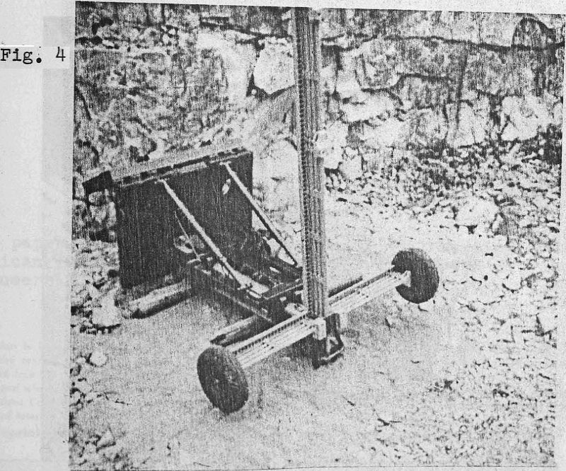
Initially, certain space requirements and preliminary work must be done at the raise site. For a 6×6 ft. raise, a compartment ten feet wide, 20 feet long and twelve to thirteen feet high must be shot out, and at one corner of the compartment the 6×6 raise driven ten feet above the compartment back. With the area cleaned out, the raise climber is ready for installation. An erecting base is built up by bolting three sections of guide rail into a special bracket forming a “T”. The Climber is brought in on its guide rail section, laid with the guide rail section down, and blocked up about one foot above the floor. The center of the “T” erecting base with its special bracket is attached to the bottom of the guide rail that contains the Climber. The long end of the ”T” erecting base is raised until it is standing vertical and the final bolts of the.special bracket are attached to the Climber guide rail. (See Fig. 4) Now, with about four good men pulling down on the long end of the “T”, the base becomes horizontal and the Climber and its guide rail become vertical and are supported by the base. Special wheels are supplied that fit in the outer end of the erecting base “T” if it is desired to move the upright Climber any distance. At the Iron King, the, wheels are not used, as the erecting base is placed on lagging and the Climber, when erected, is within a few inches of its desired location. Any minor adjustment is done with a bar. The Climber is adjusted for position and is tilted for inclination by adjusting bolts in the special bracket.
Using the Climber, platform, sections of guide rail are bolted on, with the special hinged section of guide rail positioned approximately two feet below the back of the large compartment. The special heavy duty rail section is placed on top of the hinged section and the Climber is run up to the desired height to bolt this section into the wall of the raise with eight bolts. The type of bolt used consists of an expansion pipe with a cone bolt inside the pipe, a nut, washer, and a U washer. After drilling a hole, the bolt with nut, washer and expansion pipe is placed through the anchor bracket of the guide rail until the threads of the bolt are seen behind the anchor bracket. The bolt is set by placing the U washer over the threads behind the bracket, and with the hook of the ratchet wrench (provided), the nut is jerked out. The nut can then be tightened with the ratchet wrench without deflecting the anchor bracket, thus the guide rail stays in alignment.
With the guide rail bolted to the raise wall, the Climber is run down and the erecting base dismantled.
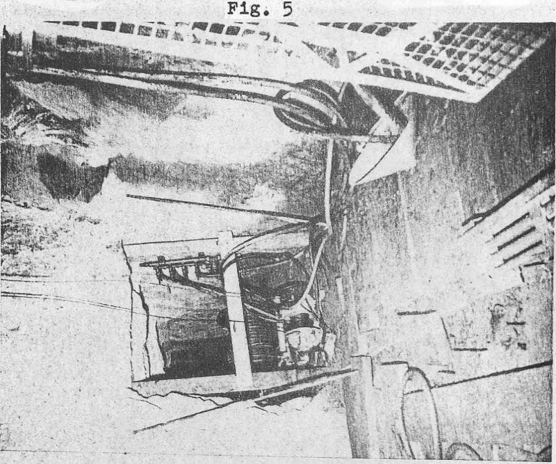
To run the Climber up and down, an air supply to the air motors on the Climber is needed, and one of the auxiliary pieces of equipment supplied is a motor-driven hose reel. This reel has a capacity of 600 feet of hose, and the hose plays out under a control arm. The arm is raised up as the hose is pulled from the reel and the reel is in neutral. When the hose slacks off, the control arm lowers and the six-tenths of a horsepower air motor begins to wind up the hose. (See Fig. 5) This hose reel is placed in the compartment on the wall farthest from the raise. The Climber can now be run to any height. A special air and water remote control manifold is provided with the Climber and is mounted in a safe place near the hose reel in the base compartment. A supply of air and water is hooked to the manifold and hoses are run from the manifold to the guide rail inlet connections just above the hinge.”
A complete raise round has the following sequence: Starting with a round blasted on the previous shift, the position of guide rail is some 10 feet below the blasted back, and has a heavy blasting plate bolted to the top. This plate has a series of drilled holes in it.
The miner first cleans up the blasted round, by mucking machine, or in the case of the Iron King operation, by slushing the muck up an inclined ramp into cars. He then turns on the air and water at the remote control manifold, and air and water is sprayed through the top blasting plate, thoroughly washing down and ventilating the raise. The men lower the Climber from its safe position and run the Climber up the raise. They bar down the back and determine the length of guide rail needed. They then run the Climber down the track and load the proper length of guide rail onto the Climber. A clamp is placed on the new section of guide rail and the rail clamp fits into a lifting pipe boot that keeps the new section parallel to the track. The Climber is run up to the top of the guide rail and positioned with the bottom of the new rail section just above the top of the track. The blasting plate is removed and the new section of jail is rotated 180 degrees, in the pipe boot, thus bringing the new section directly over the guide rail track. The Climber is lowered and the new section bolted into place. Now the Climber is run up the new section and using a jackleg the holes are drilled through the anchor bracket and the rock bolts placed and tightened. The Climber is then run to the bottom of the raise.
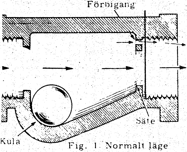
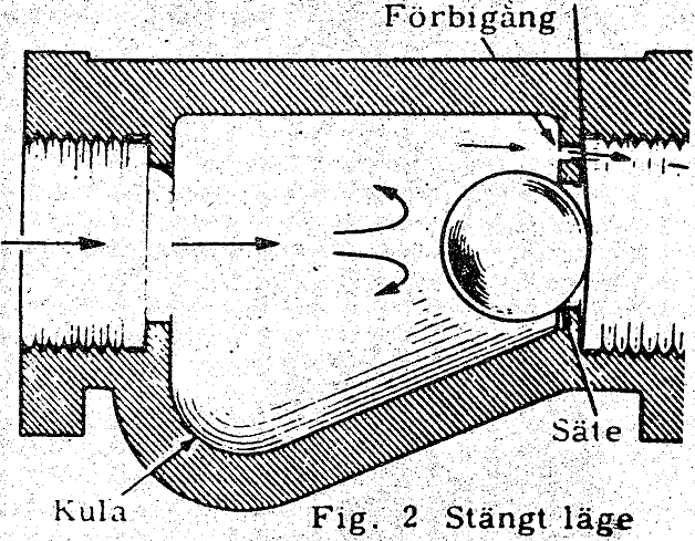
The water and air are turned on at the base remote control manifold; the valve in this manifold is shown in Fig. 6. When the shut-off valve is opened rapidly, the ball rolls up the incline, shutting off the air or water. You will notice in the drawing of the valve a small by-pass at the top which allows a small amount of air or water to pass continually. When either the water or air is turned on, the valve shuts off the water or air up the guide rail as the top is open. Now the Climber is run up with the stopers loaded on the drilling platform. A plate with valves and hose connections is placed on the top of the guide rail and bolted down. The valves are left open until the plate is secure and then turned off. The small amount of air and water coming through the by-pass now builds up pressure against the closed valve at the top of the guide rail. When the pressure is equalized, the ball rolls down the incline and the valve at the top of the guide rail can be turned on slowly, not disturbing the ball in the remote control manifold, and a full flow of air or water will now flow to the drilling machine manifold in the Climer.
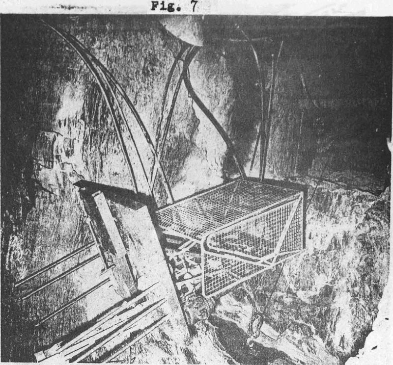
After the round is drilled out, the hoses are unhooked, and when the valves on top of the guide rail are opened quickly, the tall shut-off valve at the remote, control manifold at the base of the Climber cuts off the flow of air and water, and the blasting plate is installed. The Climber is now run to the bottom of the raise. The shut-off valves are turned off. The Climber is uhloaded and then loaded with powder. The Climber is run up, the holes charged, and the round wired. The Climber is run down while the lead wire is played out. A small tugger hoist with cable run through a sheave in the roof of the large compartment is hooked to the bottom of the guide rail (See Fig. 7). The tugger pulls the Climber up under the brow; the round is then fired electrically.
The climbing speed of the Alimak is 40 feet per minute; the lowering speed is 60 feet per minute, and the Climber will lift a load of 1100 lbs. The largest piece when dismantled is 4′ 10″ by 2′ 7″ by 1′ 3″, and the complete weight of the Climber is 1500 lbs.
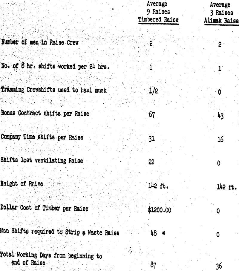
A comparison of the Alimak Method can best be shown by tabulating results of our previous raise method with the Alimak Method. The Iron King Branch of Shattuck Denn Mining Corporation has been driving a three-compartment timbered raise using a center manway and two chutes for fourteen years. However, for the purpose of this paper, the 1959-60 average of nine raises will be compared to three raises driven by the Alimak Method.
From the tabulated results it is quite obvious that many savings have resulted. The tramming crew formerly needed to pull the raise chutes is eliminated, as the Alimak crew handles their own tramming.
The bonus contract shifts required to complete a raise under the Alimak , Method is 64% of the shifts necessary to complete a timbered raise. The Company time shifts have been practically cut in half. Twelve hundred dollars worth of timber is saved in each raise, ventilating time is eliminated, and raises are completed 2.4 times faster.
The Alimak Raise Climber, essentially a track climbing drill platform, has proven its claims at the Iron King Branch of the Shattuck Denn Mining Corporation with the completion of only three raises.
