A laboratory trial to first prove the concept was followed by full scale plant trials to prove the efficacy of the design compared to a current market leader rotor/stator supplier.
LABORATORY TRIAL
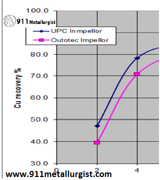
The laboratory trial was carried out at the AMML laboratory in Gosford by Graeme Sheldon on a copper ore from Queensland. This trial was purely to establish if the design was heading in the right direction and would in fact improve flotation performance of a cell. Samples were taken in 2 minute intervals and the recoveries measured. At the 6 minute mark recoveries of the F1 rotor were 8% better than that of the competitor rotor.
PLANT TRIAL
The trials were conducted at a platinum group metals concentrator which has two banks of 9 rougher/scavenger flotation cells of 50 & 75 m³. In total the mine has 76 flotation cells.
Part 1. – The initial trial consisted of installing a rotor into the last cell of one of the rougher cell banks. The Outotec and the UPC F1 rotors were swapped on occasions to ensure the results were rotor dependent rather than any extraneous factor. An increase in recovery of 3% in this one cell was achieved by the F1 rotor when compared to the Outotec rotor.
Part 2. – Following the initial trial the mine management decided to convert the complete bank to the F1 rotor/stator system for comparison purposes. The retrofitting was done in stages to gauge the impact of the F1 rotor when compared to the existing rotors. Each stage consisted of converting 3 cells at a time until all the cells had been converted.
The Chart below compares the recoveries with the type and number of installed rotor/stators. The first point is where all 9 cells were fitted with Outotec rotors and stators. The second point is where 3 cells were converted to the F1 rotor and stator. The third point with 6 and the fourth point with all 9 being converted. The last point on the chart shows that despite being worn the recoveries were still significantly better than the original rotors.
All the other variables such as liberation, reagent suite, power etc. were kept constant only the rotors and stators were changed.
There were no other costs involved in the conversion the rotor and stator are designed to simply bolt into place.
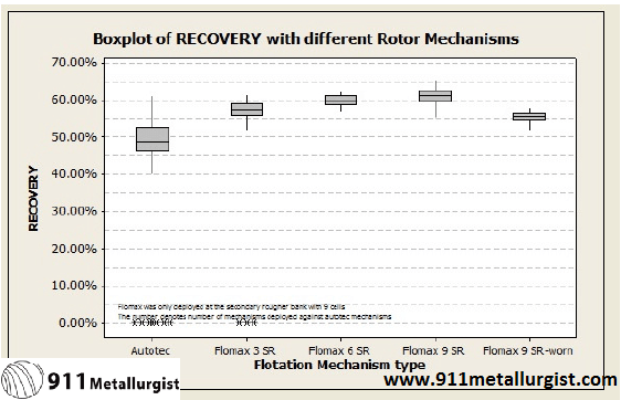
Starting from such a low base the improvements have been dramatic (13%) and exceeded the mines expectations. Such an increase in recovery would not be expected where the recoveries are already in the nineties. However, significant improvements would still be expected in recovery as well as secondary benefits such as operating stability, power and maintenance cost reductions.
Rotor Design
The F1 rotor was developed from our understanding and use of modern day fluid dynamics. Considering that the current rotor design is based on a 70 year old concept, when there was little understanding of fluid dynamics, it is no wonder a modern rotor such as the F1 rotor outperforms these older machines.
The F1 rotor specifically improves on 3 critical areas of performance;
- solids suspension
- air dispersion
- in tank circulation
These features typically lead to the following benefits;
- improved recoveries
- more stable operating conditions
- lower reagent consumption
- better recovery of fines
- lower power consumption
The rotor and stator costs are similar to current market costs so there is no downside for the concentrator operator. Further no modifications are required to fit the F1 rotor and stator.
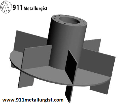
F1 FLOTATION ROTOR
Below is a summary of how the UPC rotor works and some of the potential benefits that can be expected from this new rotor on your flotation machines.
One of the most obvious benefits will be the full utilisation of each flotation tank.
Figures 1 and 2 explain this by comparing the respective flow patterns.
In figure 1 the green shaded areas indicate the inactive zones where there is little or no flow of slurry.
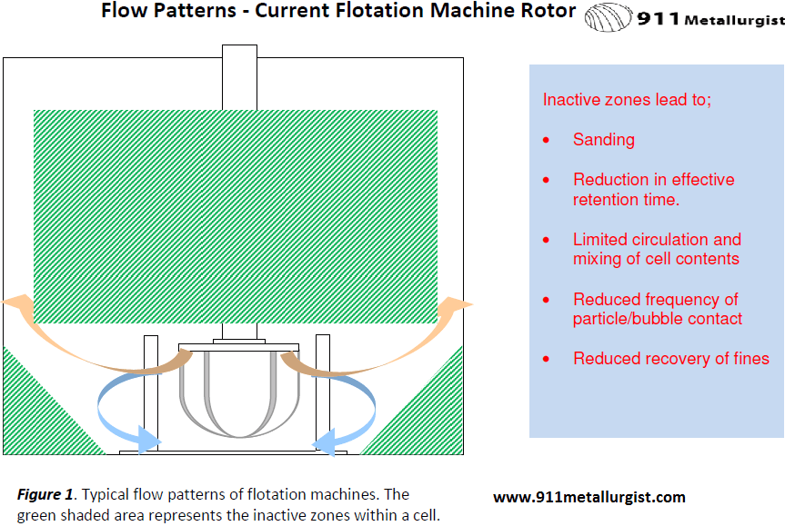
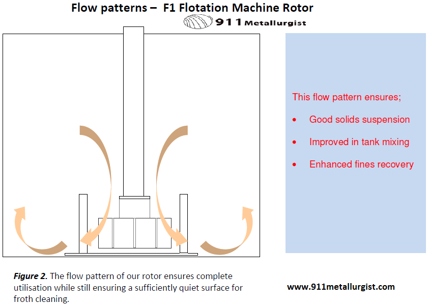
SOLIDS SUSPENSION – the flow pattern of the F1 rotor will eliminate ANY solids settling and stratification that occurs as a result. Please note that the quiescent zone just below the froth is still maintained by our rotor.
FULL UTILISATION – The immediate benefits would be, reduced number of machines required. This would represent cost savings in power, maintenance and capital expenditure. In an existing plant you would benefit from increased recoveries.
AIR DISPERSION – A further feature of our F1 design is the way all the air meets the slurry in a high shear zone. This results in better air dispersion and uniform bubble sizes and hence improved recoveries.
POWER SAVING – Because of our improved design the flow through the rotor is greater (no short circuiting) it is, therefore, likely that the mechanisms can be slowed down by 10 – 20%. This translates into a power saving of between 30 – 50%.
Trials conducted on a Platinum Plant in both 50 and 75m³ cells have shown marked improvements in recovery.
To summarise, the benefits you could expect would be;
- Lower capital costs
- Faster and improved recovery
- Lower power consumption
- Longer wear life
- Less expensive wear components
- No conversion costs – our rotors simply bolt on as your existing rotors do
Certainly coarser particles will not be a problem as they will be suspended and report to the air dispersion zone. However, the biggest area of improvement is probably the flotation of fine particles.
With the current rotors there is minimal top to bottom circulation and so the coarse particles will report to the bottom regions and displace the finer particles which will sit in the large volume above the rotor – well away from the high shear zone.
Our rotor has a different flow pattern which ensures good top to bottom circulation and so this stratification is nullified and the fines particles will flow through the high shear zone several times.
