Fouling of carbon with associated deactivation is fairly rapid in CIP circuits. Acid washing and elution only partially reactivate carbon and so for its repeated use, thermal reactivation after each loading is essential.
Reactivation kilns are basically of two types; rotary kilns and vertical kilns. The use of rotary kilns is widespread but generally they have proved to be more expensive in terms , of capital and maintenance costs and also they offer low thermal efficiency, when compared with the more recently developed vertical kilns.
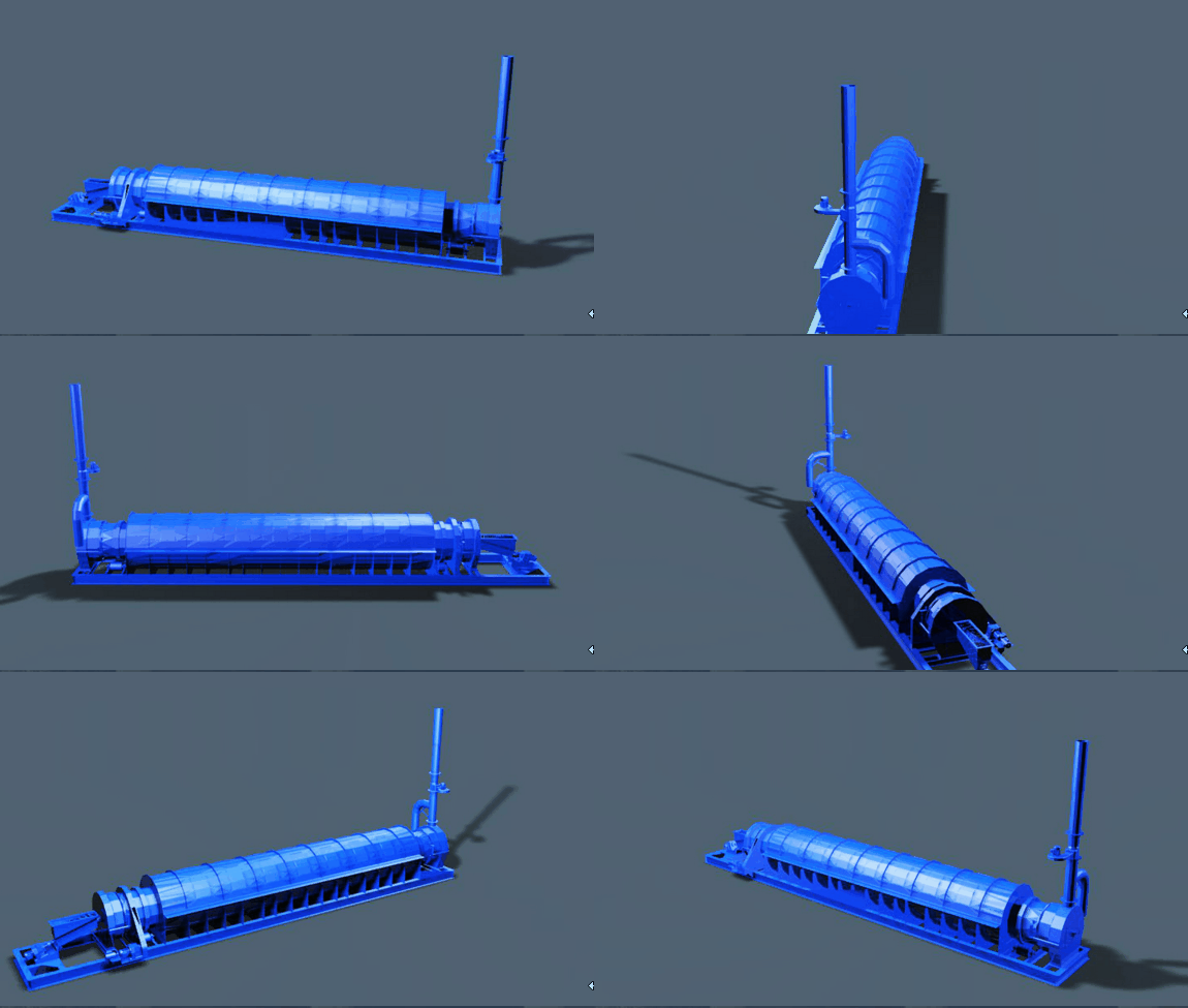
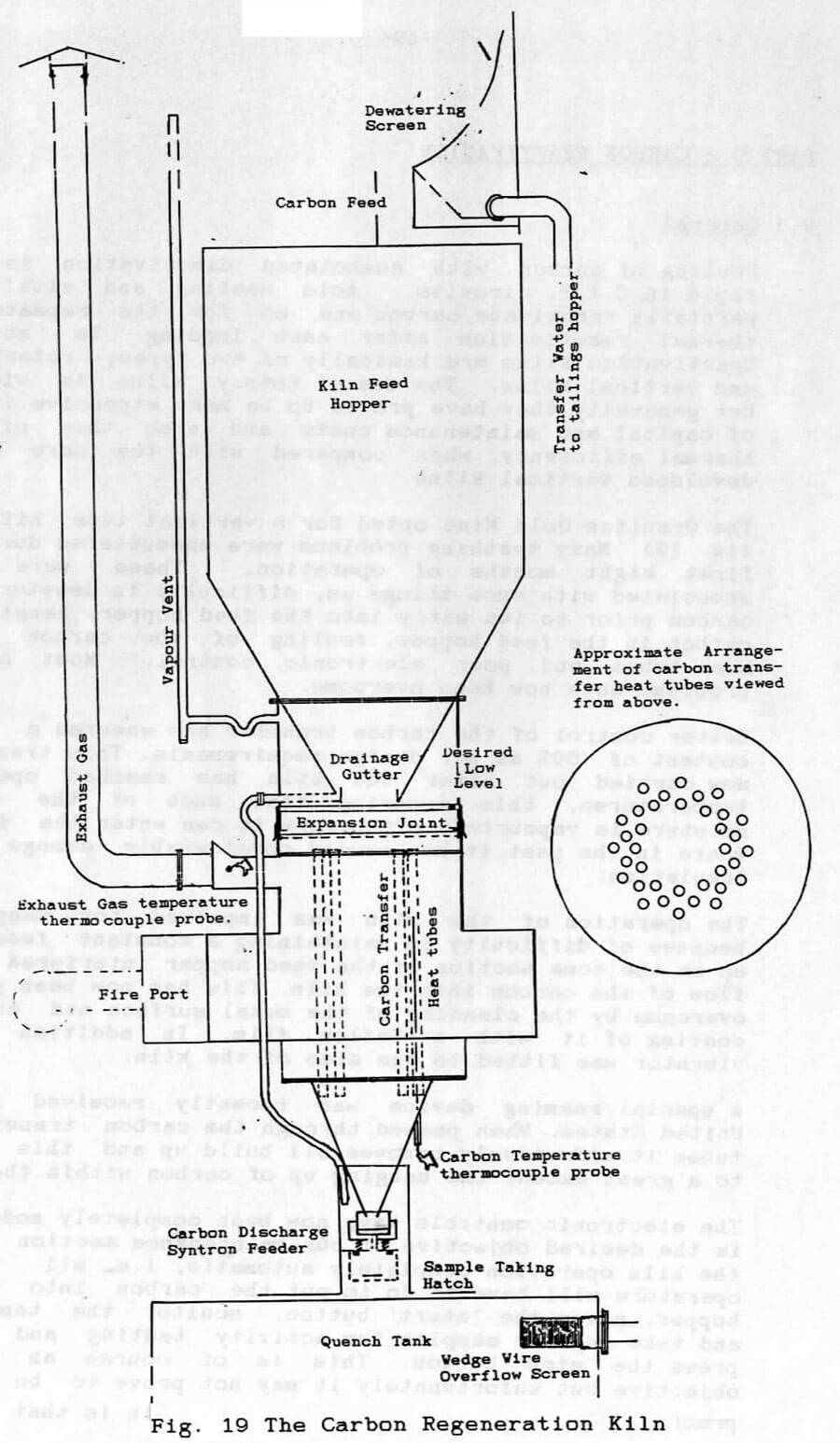
Our example is on of a vertical type kiln. (See fig. 19) Many teething problems were encountered during its first eight months of operation. These were mainly associated with such things as, difficulty in dewatering the carbon prior to its entry into the feed hopper, hanging up of carbon in the feed hopper, fouling of the carbon transfer heat tubes and poor electronic control. Most of these problems have now been overcome.
Better control of the carbon transfer has ensured a moisture content of <50% as per design requirements. This transfer is now carried out after the kiln has reached operational temperatures, this ensuring that much of the residual moisture is vapourized off before it can enter the fire box where in the past it has caused considerable damage to the insulation.
The operation of the kiln was impaired for many months because of difficulty in maintaining a constant feed. Build up on the cone section of the feed hopper interfered with the flow of the carbon into the kiln. This has now been partially overcome by the cleaning of the metal surface and subsequent coating of it with a Teflon film. In addition a small vibrator was fitted to the side of the kiln.
A special reaming device was recently received from The United States. When passed through the carbon transfer heat tubes it effectively removes all build up and this prevents to a great extent the hanging up of carbon within the tubes.
The electronic controls have now been completely modified. It is the desired objective of our maintenance section to make the kiln operation completely automatic, i.e. all that the operators will have to do is put the carbon into the feed hopper, press the ‘start’ button, monitor the temperatures and take regular samples for activity testing and finally, press the ‘stop’ button. This is of course an admirable objective but unfortunately it may not prove to be entirely practicable. A feature of this type of kiln is that the rate of carbon movement through it does tend to vary, especially during the early hours of each reactivation. During this period it is desirable that adjustments be made to the discharge feeder setting and/or to the exhaust gas setting. With the present system of controls a change in the discharge feeder setting can upset the controls completely. It is therefore essential that the operators fully understand exactly what each readout display represents and what each control does so that they are completely aware of the consequences of making any adjustment.
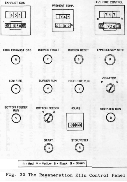
Start Up Procedure (See Fig. 20)
- If starting from cold, i.e. a new regeneration:
(i) Make sure that the feeder switch (on the side of the kiln control panel) is in the ‘on’ position and that feeder setting is on 5.25.
(ii) Press the “start’ button.
- b. If starting after a “high exhaust gas’ temperature fault light indicates:
(i) Press the black “burner reset’ button.
(ii) Press the “start’ button.
(iii) Check to see that there is a carbon discharge.
- c. If starting after a “burner fault’ light indicates:
(i) Reset the black box controller – on the back of the burner unit.
(ii) Press the “start1 button.
(iii) Check to see that there is a carbon discharge.
LED Readouts
High Exhaust Gas
This is a safety device working off the exhaust gas thermocouple probe. When the exhaust gas temperature reaches the upper limit of the setting, e.g. as illustrated on fig.20 450 + 99~, the “high exhaust gas’ temperature light will come on and the kiln will shut down. Restart as per 9.2b above.
Preheat Temperature Readout
This is a safety device designed to protect the kiln from the impact of sudden heating. The burner will operate on “low fire’ until the preheat setting, e.g. lOO Deg C as illustrated in fig. 20, is reached. During this period the green light has been reached this light will change to red and:
- The discharge feeder will start.
- The ‘high’ fire will come on.
- The vibrator will operate intermittently as per a preset cycle.
High/Low Fire Control
If the carbon temperature falls below the set point, e.g. as illustrated 720<=,C, the “high’ flame will come on. When the , temperature reaches the upper limit (720 + lO^’C) , the “high* fire will go out. The light by the readout will be red when the high fire is off and green when it is on.
Shutting; Down the Kiln
- For normal ‘end of regeneration* press the red “stop/reset* button at the bottom of the panel. The fan only will continue to run for two hours.
- For emergencies only, press the large red ’emergency stop’ button. Everything including the fan, will stop. (Emergency stop buttons will shortly be installed in two positions a safe distance from the kiln. The use of these buttons for anything: other than an emergency will cause unnecessary damage to the kiln and burner unit.)
Adjustment of the Rate of Carbon Discharge
- Switch the ‘bottom feeder* switch to ‘manual*. The feeder will then run continuously.
- Adjust the feeder control setting on the box on the side of the kiln control panel. Confirm the rate of discharge by taking a physical sample over 15 seconds and multiplying its weight by 0.24 to obtain kgs./hour The ideal discharge should be at least 85 kgs./hour and no more than 110 kgs./hour.
- Switch the ‘bottom feeder* switch back to ‘auto*.
Adjustment of Vibrator Intensity
- Switch the (vibrator) switch to ‘manual*. The vibrator will then run continuously.
- Adjust the vibrator control setting on the box on the side of the control panel.
- Switch the ‘vibrator’ switch back to ‘auto*.
Points to Watch
- The rate of carbon discharge setting is critical to the automatic control mode. A sudden increase in the rate of discharge will prompt the ‘high* fire to come on and stay on as it is governed by a probe in one of the carbon transfer heat tubes. This will cause a rapid increase in the ‘exhaust gas* temperature and could result in a ‘high exhaust gas* temperature shut down.
- When the exhaust gas temperature readout is very high slow the feeder down and monitor the temperature continuously. Should it be constantly too high with a normal carbon temperature (around 720,=,C> and likewise a normal discharge rate, it may be necessary to get the electricians to increase the exhaust gas setting. The readout plus the upper limit should never go above 580°C.
- Should it be suspected that the carbon is sticking up in the tubes it is permissible to turn up the discharge feeder, e.g. from 5.25 to 5.5, until such time as the carbon runs more freely.
- Monitor the kiln regularly. Take hourly samples and label the combined sample: “REGEN. NO. _ STRIP NO. _ DATE _ Activity”
- Fill in the regeneration log sheet every hour.
- Do not let the kiln run empty as is is necessary to have carbon in the tubes for the next start up. The regeneration should be stopped when the carbon in the feed hopper is just above the drainage gutter. (See fig. 19) It is not advisable to leave the cone section covered with carbon as this may result in a build up on the metal surface and subsequent impediment of carbon flow into the kiln. It is hoped to have a low level cut out fitted to the kiln feed hopper soon.

