Cone Crusher SPIDER CAP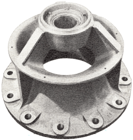
The cast steel spider cap has been designed to serve as a feed distribution plate for coarse materials. It is recessed on the 22, 30, 36 and 48-in. crushers. For fine materials, the wobble plate feeder — a more effective means of distributing the feed — is recommended.
TOP SHELL AND SPIDER
The annealed cast steel top shell and spider are made in one piece. The spider is of the three arm type, equipped with a self-aligning, Scor-Proof plastic ball and socket bearing in crusher sizes 22 to 48-in., and with an hourglass type bearing in sizes above 48-in. The lubricant is sealed in with a garter type oil seal. Bearings can be lubricated from outside the topshell on the 51, 60 and 84-in. crushers through oil holes in spider caps of the four smaller sizes.
Cone Crusher MAINSHAFT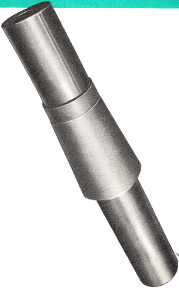
The mainshaft is of high grade forged steel, annealed for stress relief. It is tapered to gauge for head center fit. The bottom of the shaft is fitted with a polished bronze step bearing. The journal for the spider bearing is formed by a sleeve shrunk on the shaft on the 51, 60 and 84-in. crushers. Short, heavy mainshaft design results in long life.
HEAD CENTER
The mainshaft is fitted with a steel head center which bored and turned to gauge for shaft and mantle fit.
Cone Crusher STEP BEARING
The step bearing consists of a bronze mainshaft step, a bronze piston wearing plate, and an alloy steel washer between the two. The washer is drilled for oil cooling and lubrication. Both the mainshaft step and the piston wearing plate are made of high lead bronze, selected to give the best bearing surface. The washer and plate are pinned in place, and the bearing surfaces are grooved to permit distribution of the lubricating oil.
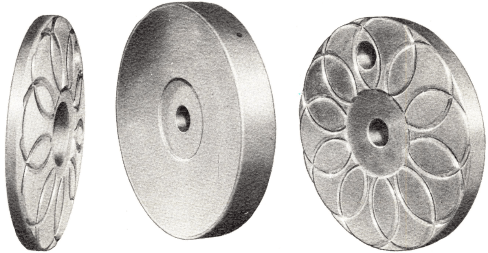
Cone Crusher MANTLE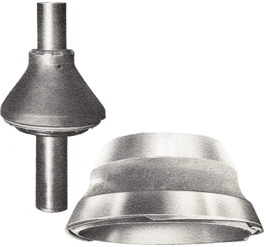
The Mantalloy head mantle of this cone crusher is a replaceable wearing surface. It is made of alloyed manganese steel, and is held in place with a self-tightening head nut. On the 51-in. Hydrocone crushers and larger, the bottom portion of the mantle is ground to gauge to fit the head center, and the top portion is zinced. For crushers smaller than 51-in., the entire inner surface of the mantle is ground to gauge and no zincing is required.
Cone Crusher CONCAVE RING
The Mantalloy concave ring, or the stationary crushing surface, is available in three standard types, coarse, intermediate and fine. Helices, cast into the bottom of the concave ring, engage similar helices on the top of a cast steel concave support ring. The support ring is held by a key to the top shell to facilitate assembly, after which it is supported on the bottom shell. The helical surfaces make the concave ring self-tightening; no zincing is required.
Cone Crusher DUST SEAL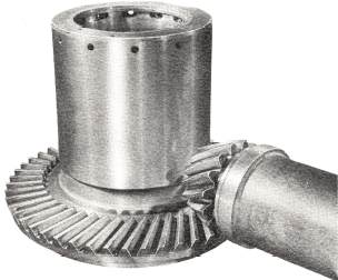
The dust seal is a plastic ring suspended in a housing from the head center and encircling the dust collar. It is designed to accommodate the vertical adjustment and the gyrating and rotating motion of the head. All wearing parts are replaceable. The crusher is fitted with a connection for introducing low pressure air inside the seal for additional dust protection.
Cone Crusher Eccentric, Gears, Pinion-shaft
The eccentric is made of high carbon cast steel and fitted with a bronze inner wearing sleeve. The eccentric turns in a bronze bottom shell bushing. Both sleeve and bushing are replaceable. The eccentric throw can be changed in the field by installing a different sleeve.
The alloy steel gear, keyed to the eccentric, is a bevel spur gear in Hydrocone crusher sizes 22 to 48-in., and spiral bevel in crusher sizes above 48-in.
The alloy steel pinion is mounted on a turned shaft. The cast steel pinionshaft housing is bolted to the machined opening in the bottom shell. It is equipped with anti-friction bearings sealed inside and out, and has separate pool lubrication in all sizes except the 36 and 48-inch machi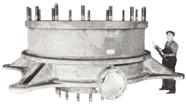 nes. The 36 and 48-inch Hydrocone crushers have sleeve type counter-shaft bearings which are lubricated by the external oiling system.
Cone Crusher BOTTOM SHELL
The annealed cast steel bottom shell is of the three arm, open discharge type, bored to gauge for the top shell and eccentric bushing. It is bored and faced for the bottom plate, pinionshaft bearing and dust collar.
Cone Crusher External Oiling System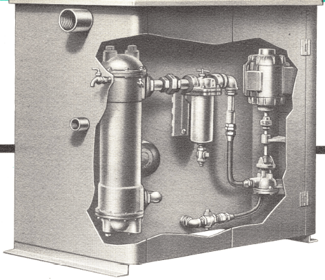
The external oil conditioning system furnished with Hydrocone crushers consists of a large oil storage tank on which are mounted a condenser type cooler, pressure type filter, motor, and a pump which pumps the lubricant to the crusher automatically. These units both cool and filter the oil. The accumulator and tank for the Automatic Reset are mounted separately from the oil storage tank.
All oil conditioning systems are equipped with oil flow and temperature safety switches which are adjusted to open the motor circuit and stop the crusher if the temperature becomes too high or if there is not a sufficient flow of oil. Flexible hose connects the lubricating unit to the crushers, greatly reducing the number of pipe fittings required and simplifying the installation.
Oil for the tank is pumped through the filter and cooler to the step bearing and up the inner eccentric bearing. It flows down the outer eccentric bearing, lubricates the gear and pinion, then returns to the tank. Tank capacities vary from 30 gallons for the 22-in. Hydrocone crusher to 240 gallons for the 84-in. machine.

REPLACEMENT PARTS FOR CONE CRUSHER
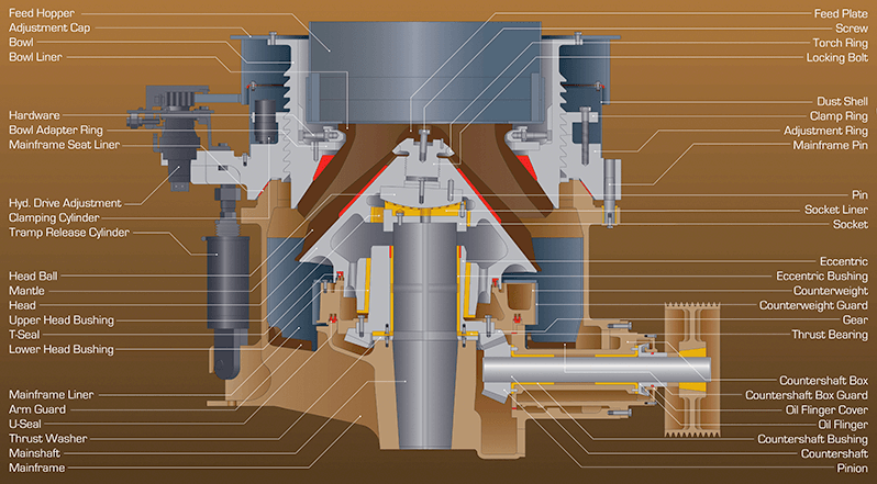
| 1. Feed Hopper 2. Adjustment Cap 3. Bowl 4. Bowl Liner 5. Hardware 6. Bowl Adapter Ring 7. Mainframe Seat Liner 8. Hyd. Drive Adjustment 9. Clamping Cylinder 10. Tramp Release Cylinder 11. Head Ball 12. Mantle 13. Head 14. Upper Head Bushing 15. T-Seal 16. Lower Head Bushing 17. Mainframe Liner 18. Arm Guard 19. U-Seal 20. Thrust Washer 21. Mainshaft 22. Mainframe |
23. Feed Plate |
Cone Crusher Components & Parts
SLEEVE TYPE SPIDER BEARING on larger size Hydrocone crushers is readily replaceable, greatly simplifies maintenance.
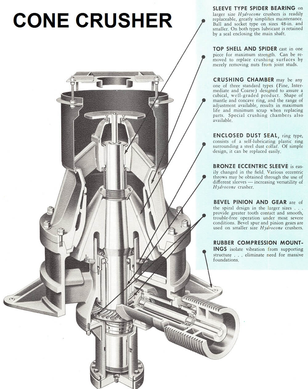
Ball and socket type on sizes 48-in. and smaller. On both types lubricant is retained by a seal enclosing the main shaft.
TOP SHELL AND SPIDER cast in one piece for maximum strength. Can be removed to replace crushing surfaces by merely removing nuts from joint studs.
CRUSHING CHAMBER may be any one of three standard types (Fine, Intermediate and Coarse) designed to assure a cubical, well-graded product. Shape of mantle and concave ring, and the range of adjustment available, results in maximum life and minimum scrap when replacing parts. Special crushing chambers also available.
ENCLOSED DUST SEAL, ring type, consists of a self-lubricating plastic ring surrounding a steel dust collar. Of simple design, it can be replaced easily.
BRONZE ECCENTRIC SLEEVE is easily changed in the field. Various eccentric throws may be obtained through the use of different sleeves — increasing versatility of Hydrocone crusher.
BEVEL PINION AND GEAR are of the spiral design in the larger sizes provide greater tooth contact and smooth, trouble-free operation under most severe conditions. Bevel spur and pinion gears are used on smaller size Hydrocone crushers.
RUBBER COMPRESSION MOUNTINGS isolate vibration from supporting structure eliminate need for massive foundations.
FORGED CRUSHER SHAFT is short and heavy designed to withstand most severe crushing stresses.
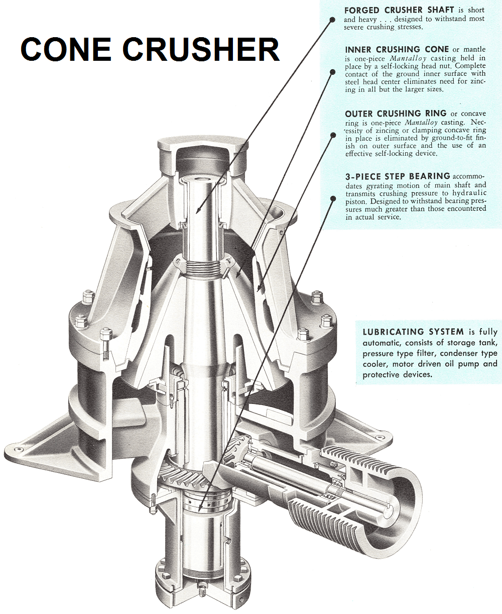
INNER CRUSHING CONE or mantle is one-piece Mantalloy casting held in place by a self-locking head nut. Complete contact of the ground inner surface with steel head center eliminates need for zincing in all but the larger sizes.
OUTER CRUSHING RING or concave ring is one-piece Mantalloy casting. Necessity of zincing or clamping concave ring in place is eliminated by ground-to-fit finish on outer surface and the use of an effective self-locking device.
3-PIECE STEP BEARING accommodates gyrating motion of main shaft and transmits crushing pressure to hydraulic piston. Designed to withstand bearing pressures much greater than those encountered in actual service.
LUBRICATING SYSTEM is fully automatic, consists of storage tank, pressure type filter, condenser type cooler, motor driven oil pump and protective devices.
Adjustment Ring
While it is one of the major parts in the machine, there are few essential differences between the adjustment ring in the 10 ft. crusher and in the smaller machines, except as to size. Material of the ring which weighs 70,000 pounds is cast steel. Rigidity of the adjustment ring cross-section is essential. In this case, increased section thickness, with ordinary carbon steels, results in a reduction in deflection.
Bowl
This part, which is screwed into the adjustment ring, is the means of setting of the machine. Adjustment is performed by rotating the bowl relative to the adjustment ring. In the 10 ft. machine provision has been made to adjust the setting during crushing. This increases the availability of the crusher substantially. Past practice had been to stop feed to the crusher during adjustment.
Clamp Ring
During crushing the position of the bowl and adjustment ring is maintained on the slant flank of the threads by means of the crushing force. The slant flank helps in centering the two elements. The clamp ring acts somewhat like a locking device to take up clearances. Ideally, the clamping cylinders do not have to have any greater capacity than is necessary to overcome the weight of the bowl. Practically, the clamp ring capacity is many times higher to withstand tramp passage.
Adjustment System
To adjust the setting of the machine, hydraulic rams are used to rotate or counter-rotate the bowl in the adjustment ring. The seal between the adjustment cap and hopper is a simple, continuous, tightly fitting flap which allows free, relative rotation but prevents intrusion of dust into the thread area. The lower end of the thread connection between bowl and adjustment ring is also sealed. The hopper assembly, which is actually a part of the bowl assembly, including the hopper, hopper liner and cap closure, comprises the section in which the feed is introduced. It includes a dead bed, reducing wear and shock from the fall of the feed from the feeder above.
The adjustment rams are pressurized hydraulically and provide a setting adjustment. For normal adjustment of setting due to wear, installation and removal of the bowl is made through a swivel sheave and a cable turn applied around the adjustment cap. The bowl is then rotated by use of the maintenance crane.
Head-Main Shaft Assembly
The crushing head, similar in section to that of the 7 ft. machine, had three-dimensional photoelastic studies made using the technique of freezing stresses into a loaded plastic model, sectioning the model and examining the slices under polarized light. As a result of these techniques, stresses have been reduced. The core of the head consists of six massive ribs to support the crushing forces on the surface of the head. The head is cast steel.
The main shaft is of turbine rotor steel of high quality and refinement, the chemistry of which is low carbon to reduce the possibility of heat checking. It includes chrome nickel additions for deep hardening, notch toughness and resistance to fatigue. The shaft extension is provided to reduce the relative strain between the head and shaft and thereby reduce fretting in the fit, which has a heavy press. The shaft diameter is 50 percent greater than the 7 ft. crusher shaft. As a result, the shaft operates at lower values of bending stress and deflection. Reduced deflection produces distinct benefits in bearing behavior because of uniformity of oil film under load. Reduced stresses assure longer life and resistance to overloads.
Socket Assembly
The head-shaft assembly is supported by the socket and socket liner which is, in essence, a spherical thrust bearing. The function is to carry the vertical component of the crushing force while allowing the head to oscillate around the theoretical center of rotation.
The socket of carbon steel is of dowelled design. The forces between the head and the socket are normal to the spherical surface of the head and pass through the theoretical center. The line of action of these forces is such that practically pure compression is applied to the socket and liner, reducing deflection and stress to a minimum and promoting good bearing performance.
Inner and Outer Bearing Design
The force distribution throughout the crusher is based on a vector diagram of the cavity forces during crushing and the reactions at various associated loading points in the crusher. The vector diagram establishes their relative magnitude, direction and points of application. The actual magnitude of these forces is established by the crushing force necessary to lift the adjustment ring off the frame seat. This condition represents the maximum allowable force for normal crushing.
During tramp passage, bearing forces increase, but this condition prevails for brief periods which are not maintained long enough to overheat the bearing and destroy the hydrodynamic oil film.
Seal Assembly
A baffle ring attached to the head is sub-merged around its entire periphery in a water trough resting on the socket. Dust tends to settle into the trough and must be continuously removed to prevent caking. For this reason, water is continuously fed through specially designed nozzles which scour the trough. Overflow water is carried off by internal piping and passages. The seal chamber is vented to atmosphere to prevent “siphoning” which may cause oil contamination of the water or vice versa.
Main Drive Gears
The gears are straight tooth bevel gears and are designed to AGMA standards using a computerized program which, upon input of the basic information, such as DP, diameters, gear ratio, material properties, tooth type, provides a complete printout of the rated power on the basis of tooth strength and surface durability of the gear. The factor of safety on the gear is in excess of three on the strength basis and in excess of two on the durability basis.