The Problem with Designing a Conveyor System
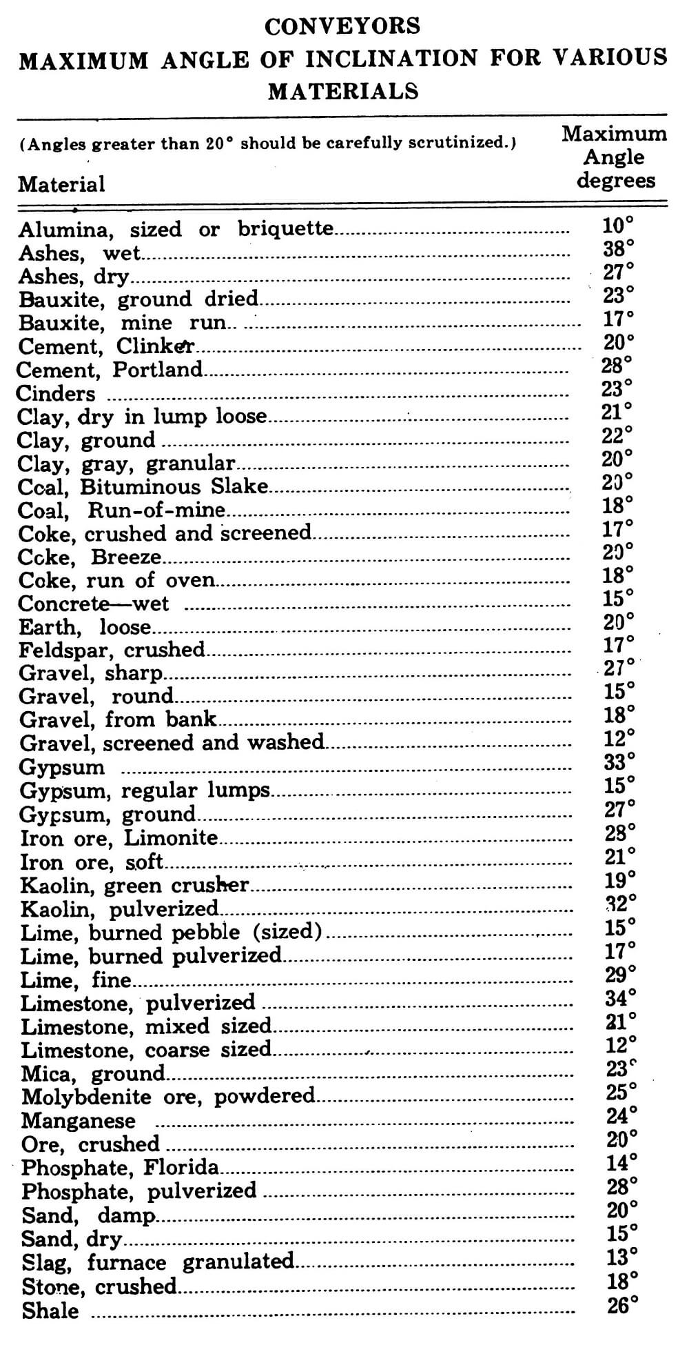
The designer of belt conveyors is often faced with problems of determining the proper belt speeds, belt widths, number of plies in the belt, and idler spacing for conveyors employed in various parts of a mill. Equipment Company offers the following data and tables, based upon many years of experience in designing all types of mills, to assist others concerned with mill design in engineering conveying systems.
Graphs shown on the next page show belt conveyor capacities and horsepower requirements for various conditions.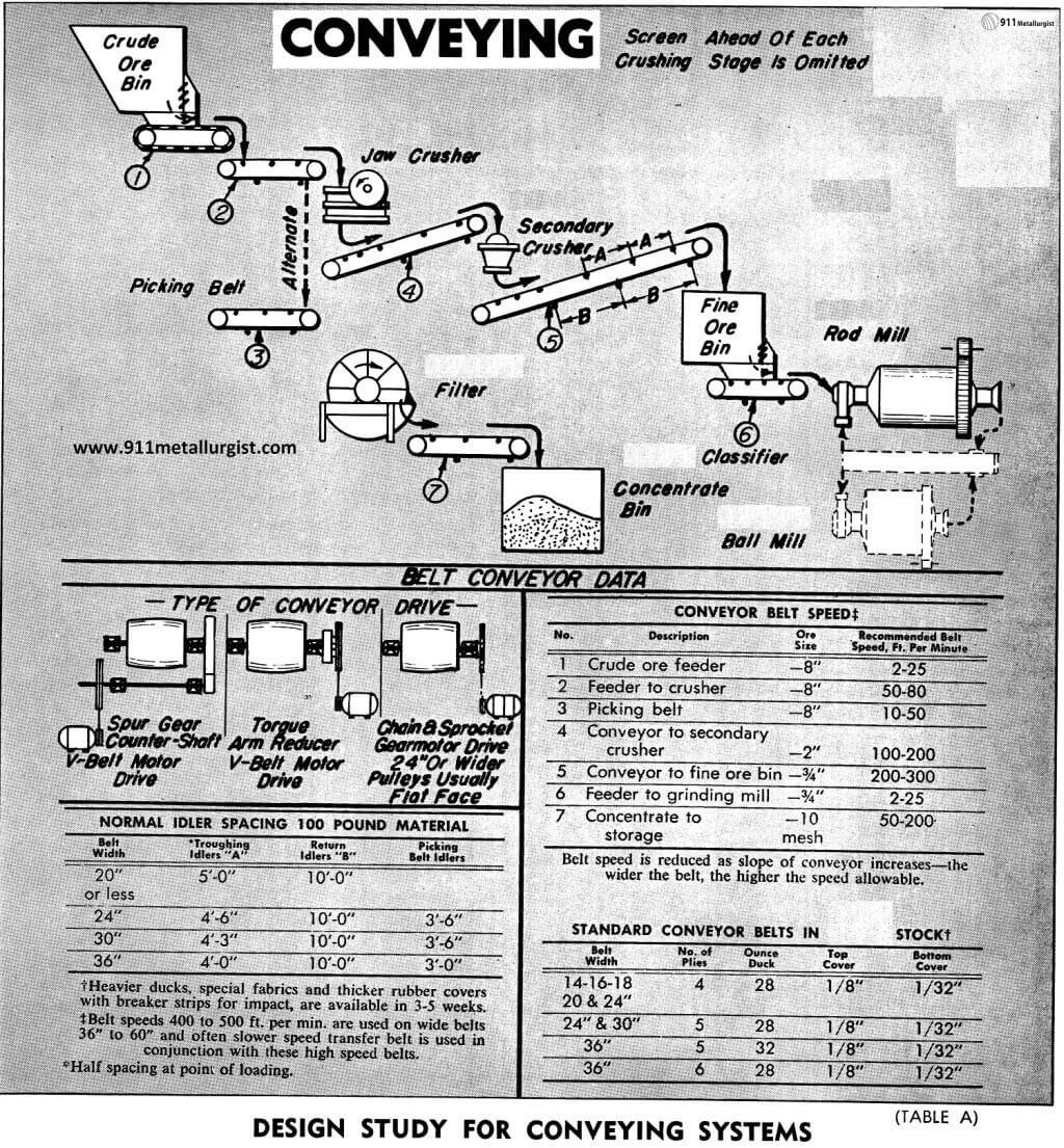
The Conveyor Design
To solve a conveyor problem, certain facts must first be known. This information is essential for sound conveyor engineering: tonnage per hour, average size of material, maximum lump sizes, weight of material in pounds per cubic foot, conveyor pulley centers in feet, whether conveyor is to operate horizontally or on an incline (18° should be the maximum inclination) and whether the application is to be as a feeder, picking belt, or for conveying crushed ore or concentrate.
In general, the number of plies and weight of belts as shown on table (A) on page 1 will be suitable for horizontal and inclined conveyors not over 300 feet pulley centers and transporting crushed ore. Where conveyors are extremely long or must convey unusually large and abrasive lumpy materials, Equipment Company engineers will gladly assist with conveying problems.
Properly engineered conveying systems can mean a material savings in both power and maintenance. A system should be adequate but not oversize to do the job intended. From the standpoint of initial cost, narrow belts are favored while slower speeds favor long life.
In most cases the design is based on known factors such as tonnage to be conveyed, weight per cubic foot of the material, size of pieces and belt speed desirable for the service intended. Suggested belt speeds for various conditions are given in table (A) under Belt Conveyor Data. With these factors established, the belt width can be obtained from the “Conveyor Selection Chart” table (B). The horsepower required can next be obtained from the chart “Horsepower for Belt Conveyors” table (C). The factors of conveyor length, belt speed in feet per minute, tons per hour and total lift are required for the use of this chart to determine the total horsepower required.
Inclined Belts
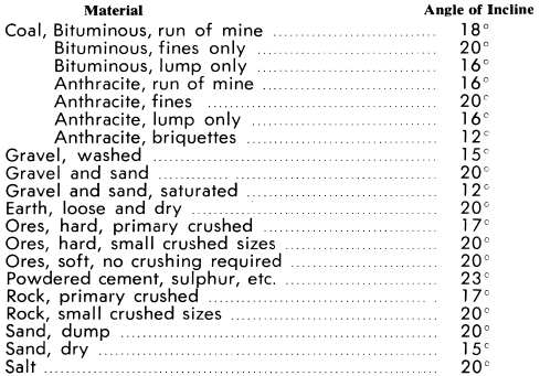
The following table gives an idea of the maximum allowable incline for various materials:
Number of plies in Conveyor Belt
For the average short-centre horizontal conveyor belt, under 300-foot centers, a 4-ply, 28-oz. duck belt may be safely used up to and including 20″ widths; 5- ply, 28-ounce duck for 24″ and 30″ belt widths; 6- ply, 28-ounce duck for 36″, 42″, and 48″ belt widths. However, where the conveyors are extremely long, or are operated on an incline, or run fully loaded at speeds below 100 feet per minute, safe belt loads must be computed by taking into consideration the horsepower pull or effective belt tension, the angle of wrap of the belt around the pulley, and the type of take-up whether it be a screw or counterweight take-up. Belt manufacturer’s tables should be referred to for determining the safe working tensions for their belts. The following working tensions may be used as a guide:
24 pounds per ply inch for 28 ounce duck.
27 pounds per ply inch for 32 ounce duck.
30 pounds per ply inch for 36 ounce duck.
38 pounds per ply inch for 42 ounce duck.
The effective tension on the belt is 33,000 times the total horsepower required at the head shaft, divided by the belt speed in feet per minute. The maximum tight side tension of the belt employing screw take-ups is the effective belt tension times 1.8 for bare pulley drive and times 1.66 for lagged pulley drives. Where a counter weighted type of take-up is employed, the maximum tight side tension is computed by multiplying the effective tension by 0.50 for bare pulley drive, and by 0.38 for lagged pulley drive.
Rubber Covers on Conveyor Belts
Most belts may be purchased from local warehouse or factory stocks with 1/8″ rubber top cover and 1/32″ thick pulley cover. The top cover should be increased in thickness if the frequency of impact or abrasive action of the material at the loading point is severe, or if the material is fed at an angle to the belt travel. The quality of rubber friction which is needed between the plies of fabric is determined by how severely and how frequently the belt is flexed. Special high temperature belts may be purchased for transporting dried concentrates ranging from 150°F. and not over 200°F.
https://www.911metallurgist.com/troughing-belt-conveyor-capacity
Motor Drives
The most popular drive is a motor-V-belt drive to a totally-enclosed running-in-oil torque arm speed reducer which is keyed to the head shaft of the conveyor. For a small additional cost an automatic backstop can be added to prevent an inclined conveyor from running backward during a power failure.
A less expensive drive is one employing one or several spur gear reductions between the head shaft and the counter shaft. A V-belt or roller chain drive is used to connect the motor with the counter shaft.
A third arrangement is a gearmotor-sprocket and roller chain drive to the head shaft, which makes for a very satisfactory and compact drive.
Feeding the Belt
For best results, the belt must be uniformly loaded. Intermittent or irregular feed produces unloaded spots which result in decreased capacity, or overloaded spots resulting in spillage over the carriers onto the deck and onto the return belt. If the job will stand the additional cost, some type of mechanical feeding device may be employed, such as a belt feeder, apron feeder, pan feeder, vibratory feeder or a reciprocating feeder.
Chutes should be so arranged that the material falls directly on the bottom wall of the chute and not directly on to the belt. The material should slide on to the belt midway between two of the troughing idlers. Skirt plates should be 4 to 8 feet long and spaced about ½ to ¾ of the width of the belt apart, being wider at discharge than at feed end. Rubber belting should be bolted to the outside of the skirts and nearly meet the conveying surface of the belt.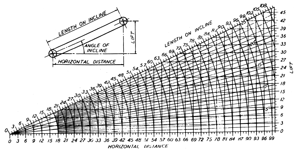
https://www.911metallurgist.com/estimating-conveyor-slope-angle
Conveyors used in coal, mineral and rock mining require a more sophisticated analysis than in the past due to the complex nature of the modern mine and its demand on equipment component design. This is particularly true in mines that use longwall extraction and long belt conveyors.
Belts with an initial length of the order of 16,000′ are now in operation, and these conveyors are usually designed to retreat as the mine face advances, placing an initial stringent design requirement on belting and components. Some of the new research methods being tested by various modeling methods for these long belts include:
- controlled starting with tripper booster drives
- profile optimization in the mine planning stage
- use of multiple take-ups and storage loops
- multiple feed points
- multi-flight vs single belts
- new belting materials
- regenerative processes in relation to predictive models
Other problems facing both new mines and those contemplating an upgrade to higher tonnages include issues related to
- seam-to-seam conveying
- upgrading equipment for higher tonnage
- run-on problems and flooding at transfers
- belting quality with regard to operation
- regenerative belts feeding onto non-regenerative belts
Most of the issues listed above require considerable analysis in order to overcome design shortfalls and potential inappropriate design implementation. Equipment suppliers are usually not in a technical position to spend considerable time and effort on such analysis. Those suppliers that do conduct up-front audits also usually cut profit margins in order to gain the contract or they pass costs on to the customer in some form.
Before any design optimization can be considered for the underground or overland conveyor, the basic fundamentals of the conveyor design need to be tested both theoretically and in practice. Feasibility studies also require a full analysis of the factors that influence conveyor design and component sizing based on model computations.
The safest form of investment for the new or expanding mine is for the mine to commission its own technical feasibility study or design audit The outcome of such audits or studies are usually beneficial and allow a clearer direction for the project implementation process.
Theory of Belt Tracking Signature
Belt mistracking is dependent on the running center-line of tension and not necessarily on the physical belt dimensions. Figure 1 shows a graph of unequal tension distributions across the width of the belt. The average belt tension is “T” and the belt width is “w”. The actual center-line of the belt tension is off to one side from the physical belt center.
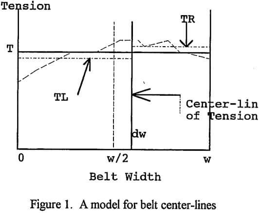
The mathematical relationship between the belt’s center line w/2 and the new center-line based on the average governing moments TL and TR (left and right moments) is
-dw = w/2 (TL – TR)/(TL + TR)
from which it is possible to:
(a) compute dw based on TL and TR measurements
(b) measure dw and T to determine the imbalance
(c) measure the reinforcement alignment and calculate the various moments.
Belt tracking dw can be measured in the field by monitoring the edge of the belt as the belt runs. This measurement will vary from position to position along the belt because of variation in belt tension. However at any one measurement location the belt tracking will repeat each revolution and this is termed a belt signature (Harrison 1981). The tracking signature tells a great deal about the belt’s load sharing quality which may be related to one or all of the following conditions:
- deviations in carcass reinforcement position (manufacturing)
- splice straightness
- belting straightness
- condition and damage levels
- repair quality
- age and internal breakdown
- temperature effects.
In addition, these conditions are usually time-dependent, that is, the condition changes from one measurement to the next. This fact is used to interpret complex variations in the belt that often indicate the onset of failure of splices and belting.
A typical tracking signature for a belt is illustrated in Figure 2. The tracking signature defines dw(t) in which the deviation of sideways motion repeats at an interval t = 2L/v where L is the belt length and v is the speed. Calibrating the mistracking permits an analysis of the variation in belt center-line of tension.
As seen in Figure 2, there are a number of characteristic events that are of belting or splicing origin. These include many of the seven points listed above. Other data is usually simultaneously recorded to enhance the interpretation of this tracking data, including tests such as:
- Non-destructive testing of the reinforcement
- Belt dynamic sag of left and right sides of the belt
- Belt vibration signature analysis of the edges
- Carry and return belt tracking signature capture.
Source: This article is a reproduction of an excerpt of “In the Public Domain” documents held in 911Metallurgy Corp’s private library.

