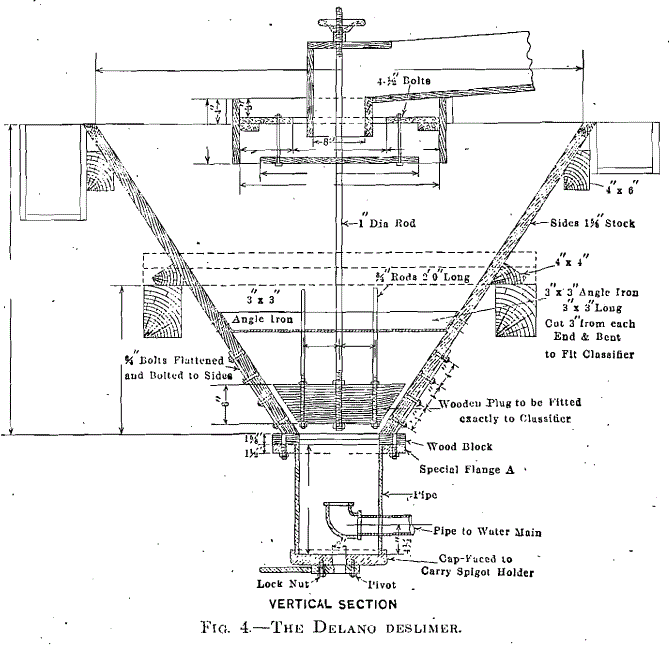
The deslimer is provided with a central feed box, having a baffled bottom to break the velocity of the inflowing pulp. The bottom, or discharge chamber, has a clear-water inlet, which directs, the flow upward along the axis of the deslimer. The spigot is inserted in a movable holder, attached to the bottom of the discharge chamber, permitting an instant change in the diameter of opening without wetting the operator. Between the feed box and discharge chamber is a valve with sides parallel to the tank and suspended on the vertical center, and which can be raised or lowered by means of a hand wheel on the suspension rod. This produces a narrow channel between the valve and tank through which the hydraulic water rises and the sands fall.
The feed entering the deslimer is checked by the baffle, causing the sands to settle through a narrow, rising current of water surrounding the valve. This current increases in velocity until the discharge chamber is reached, by which time the sands are thoroughly deslimed. A hydraulic pressure of 5 or 6 lb. per square inch is maintained in the discharge chamber. The width of the sorting column may be varied by raising or lowering the valve. No whirling or boiling currents are possible and the steady rising current gives a very close separation. The great efficiency of the deslimer is due to the better application and direction of hydraulic water supplied. A deslimer 5 ft. 6 in. in diameter treats from 350 to 400 tons per 24 hr., using approximately 120 gal. of hydraulic water per minute.
