There are two parallel dry grinding circuits prior to roasting. Crushed ore is carried to the two circuits by the two reclaim conveyors located below the crushed ore stockpile. The feed rate of the crushed ore into the grinding mill is controlled by the apron feeders under the stockpile and measured by the belt scale located on the reclaim conveyor. Lime is added to the reclaim conveyor upstream of the belt scale by screw feeders to control SO2 generated in the drying chamber of the mills. A magnet, located along the reclaim conveyor upstream of the belt scale, is used to remove the remaining tramp metal in the crushed ore. A metal detector is located near the end of the reclaim conveyor to prevent non-magnetic metallic objects from entering the mill. When metal is detected, the mill feed system shuts down, and the metal detected is removed from the belt by hand. This is done because of the sensitive of the drying chamber.
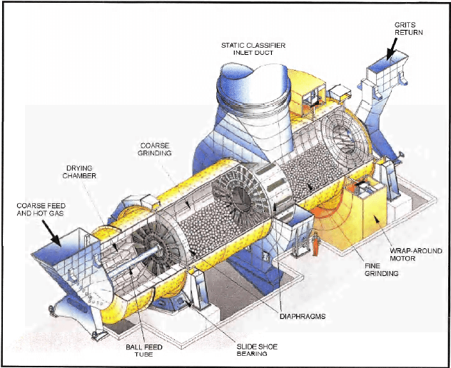
Crushed ore is fed into the drying chamber of the grinding mill through a double flap feed valve and a retractable inlet chute. The feed valve is used to prevent the ingress of infiltration air. The lifter plates of the drying chamber scatter the crushed ore into a hot gas stream that serves as the drying medium. The hot gas stream is produced in the propane fueled air pre-heater. A fan supplies hot air from the air pre-heater to the feed valve as required to prevent sticking in the valve. A lifting diaphragm at the end of the drying chamber conveys the material into the first grinding chamber. Between the first and second grinding chambers is the central discharge device (CDD). There are diaphragms located between the grinding chambers and the CDD. The CDD discharges ground material from both the first and second grinding chambers through openings in the mill shell.
(2 Lines) Double rotator 19’ X 69’ mills – Krupp Polysius 19’D x 69’ L
10.0 hp variable speed wrap around motor
Ball charge at 29% Coarse side (#1 side) – 4” balls Fine side (#2 side)- 2” balls
Moisture is between 5% and 9%
Dynamic classifier splits 20% to coarse side – 80% to fine side
Variable speed – 500 hp
2,000 HP Dynamic & Static classifier fans General Electric Motor
Wheelabrator Jet III Dust Collectors (8) 784 Filter bags per unit 230,000 acfm gas volume
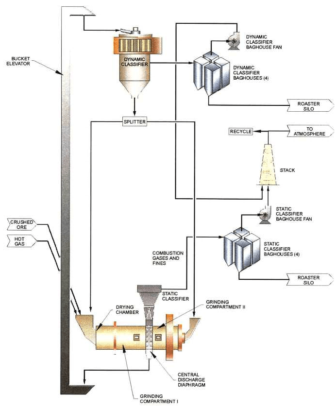
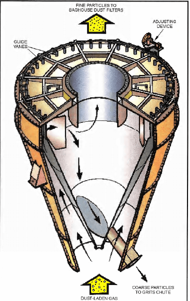
Fine ore from the first and second grinding chambers is elutriated (separated) from the coarse ground material within the mill and CDD. It is transferred with the off-gas to the static classifier (29’ 6”), which is located immediately above the mill. The static classifier further separates the large and small fines with a 74 micron cut point, discharging the large fines to the oversize bucket elevator and the small fines to the static classifier baghouse.
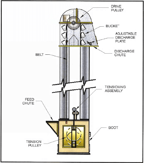
The coarse ground material from the first and second grinding chambers is discharged from the bottom of the CDD to the oversize bucket elevator via an air slide located underneath the grinding mill. The coarse ground ore is subsequently transferred from the oversize bucket elevator, via another air slide, to the dynamic classifier.
The dynamic classifier separates the fines from the coarse ground material with a 74 micron cut point. Ground ore is fed into the dynamic classifier through a feed chute centrally located above the classifier. The fines and coarse material in the ground ore are classified within the separating chamber. Coarse material is returned to the first and second grinding chambers via the underflow splitter, cascade chutes and two air slides in series per chamber. Ore fines are transferred with off-gas to the dynamic classifier baghouse.
Grinding mill product collected in the static classifier baghouse is transferred to the roaster silo by means of air slides and tipping valves. Product collected in the dynamic classifier baghouse is transferred to the roaster silo by means of air slides, tipping valves and another two air slides in series. There are two roaster silos; each fed by one grinding mill. Clean air discharged from the baghouses is emitted to the atmosphere through the grinding mill exhaust stack, with a permitted dust loading of 0.008 grains per standard cubic foot. A bleed of static classifier baghouse off-gas rejects the moisture from the ore to atmosphere. The bleed stream flowrate must be high enough to maintain the mill off-gas moisture content at less than 20% v/v. The remaining static classifier off-gas is recycled to the air pre-heater via the static classifier recycle fan. The dynamic classifier baghouse air is also recycled, with a bleed stream that rejects infiltration air from the circuit. The static and dynamic baghouse bleed streams are emitted to atmosphere through the mill stack. The bypass options are fuel conservation, so we will not have to reheat the stream.
Any dust collected within the grinding circuit is recovered within the baghouse. Fines from the baghouse are discharged through an airslide and rotary airlock to the second roaster silo feed. Clean air discharged from this baghouse is emitted to the atmosphere. A vacuum cleaning system cleans up ore spills. The vacuum cleaning system is used because it is critical not to get any preg robbing material in the C.I.L. circuit.
DOUBLE ROTATOR BALL MILL
DRY GRINDING SCHEMATIC
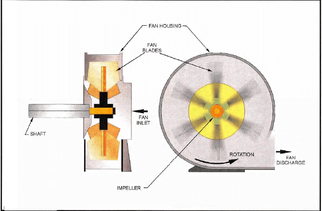
CENTRIFUGAL FAN
Static Classifier
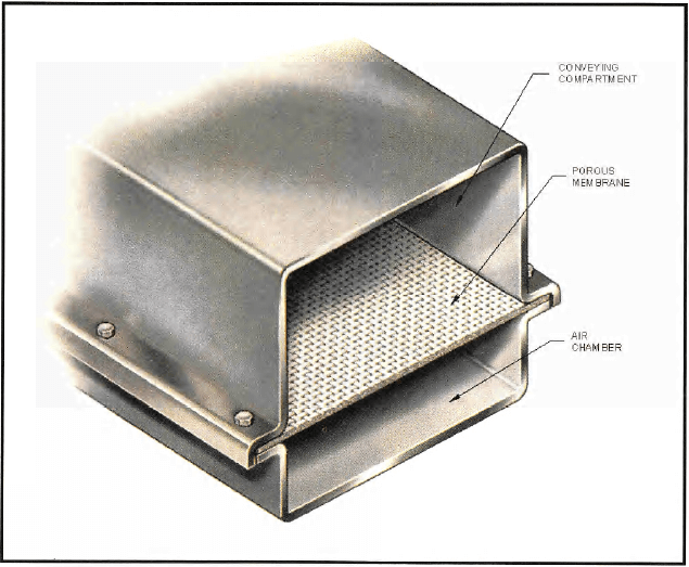
AIRSLIDE
Bucket Elevator
DYNAMIC CLASSIFIER
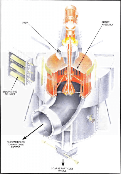
SEPOL high efficiency separator
The granular material is conveyed in the middle of the classifier on a distribution plate which universally distributes the material in the separating chamber. In the separating chamber mass and air flow forces separate the material into fine and coarse material.
The coarse material falls into the bottom of the hopper and is conveyed to grinding chamber #1 and #2 via the flap valves.
The fine material is conveyed with the separating air out the discharge and into the baghouse which separates the fine material from the air. The air flows back to the chamber via the fan. The fine material leaves the filter via the discharge unit and is conveyed to the silo.
Grinding the discharge in side #2 of the grinding mill
In normal operation, the discharge from the classifier is mainly fed to the #2 grind side where it is ground. The #2 grinding side is filled with smaller grinding material and equipped with a lifting classifier liner which ensures the ball charge will become correspondingly finer with the grinding process. After the fine grinding, the material is conveyed through the slotted plates of the diaphragm into the central discharge housing and from there to the separating systems downstream.
Feeding the discharge back into the #1 side of the Mill.
The discharge can also be partially fed into the grinding chamber #1 via the change over flap: the relatively fine discharge improves the flow behavior of the coarse feed material.
