More profit can be earned by using the Flash Flotation Cell in the grinding Circuit. This machine has been designed especially for the recovery of floatable minerals at a coarse size as soon as the mineral is free; together with the finer sizes.
Even though many ores require fine grinding to make the maximum recovery, most ores liberate a large percentage of the mineral values during the passes through the grinding unit. By placing a Flash Flotation Cell between the grinding unit and classifier it is now possible to quickly save the free mineral values from the coarse gangue at a low cost.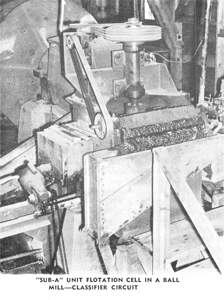
Since the machine is capable of operating at high pulp densities and is especially designed for handling this condition, it is practical to use the machine in almost any grinding circuit and in almost every instance it is necessary to supply additional water to the discharge from the Flash Cell in order to obtain the dilution desired for the subsequent classifier overflow. This means that the machine can be installed in the usual grinding circuit without upsetting the mill control or changing conditions in the mill flowsheet and without pumps or elevators.
Advantages of a
Flash Flotation Cell
- LOW INITIAL COST—Any operating plant can easily afford a Flash Flotation Cell. Many operators have experienced such decided advantages that the cost of the unit was more than repaid in a few weeks’ time.
- SIMPLICITYOF INSTALLATION—The Flash Flotation Cell can be incorporated into practically any grinding circuit. The discharge is at a considerably higher elevation than the feed inlet, permitting installation in closed circuit without the use of pumps or auxiliary equipment.
- LOWER FINAL TAILINGS are produced because the removal of mineral as soon as it is free results in lowering the value of classifier overflow, permitting the effective use of subsequent capacity, and removing peak conditions.
- INCREASED CAPACITY can be gained by the use of the Flash Flotation Cell in the grinding circuit. The unit provides a finished high-grade concentrate, removing this material from the circulating load as soon as it is discharged from the ball mill. This permits the addition of more fresh ore.
- HEAVY RUBBER WEARING PARTS AND LINERS used in the Flash Flotation Cells are an achievement which has made possible the handling of coarse and abrasive pulp of high density at unusually low replacement cost.
- LOWER REAGENT COSTS for mill operation have resulted from the use of Flash Flotation Cells. The recovery of large amounts of free mineral at coarse sizes promotes maximum flotation efficiency and reduces the amount of the slimed mineral which absorbs and requires large amounts of reagent.
- INCREASED FILTER CAPACITY has been the result of adding the coarse Flash Flotation Cell concentrate to the regular flotation concentrate.
- LESS POWER is required. Due to the operation of the cell at high pulp densities and recovering the material in a coarse and granular nature, less flotation time and less horsepower input per ton of concentrate produced is required. Less power is also needed for grinding circuit.
- MORE PROFIT is realized since in addition to lowering reagent costs, reducing tailing losses and increasing capacity there is often an added advantage of the production of higher grade concentrates which can be marketed with greater net return.
- NO SUPERVISION is required for the operation of a Flash Flotation Cell because it treats the ball mill discharge automatically and the operator need be concerned only with the normal operating control of the grinding circuit. No special reagents are required; the total reagent consumption is equal or less in plants where Flash Cells are now operating.
Specifications
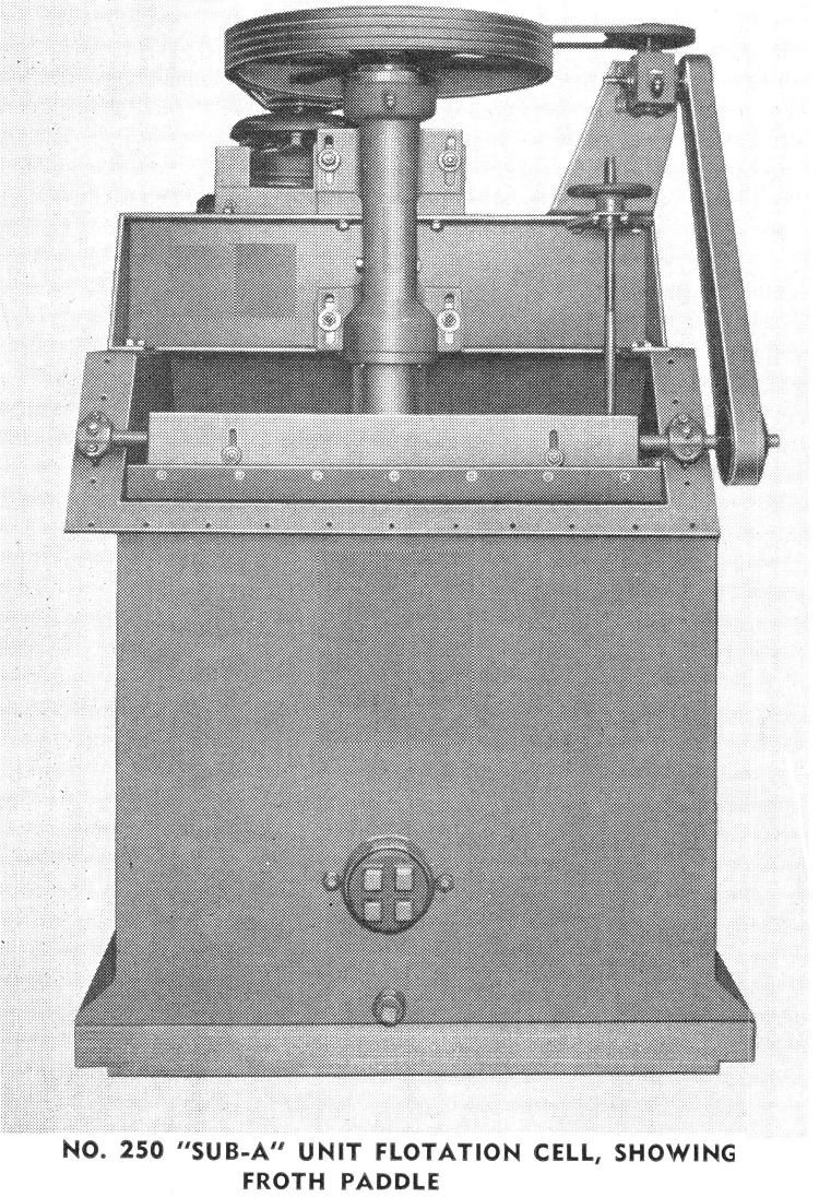
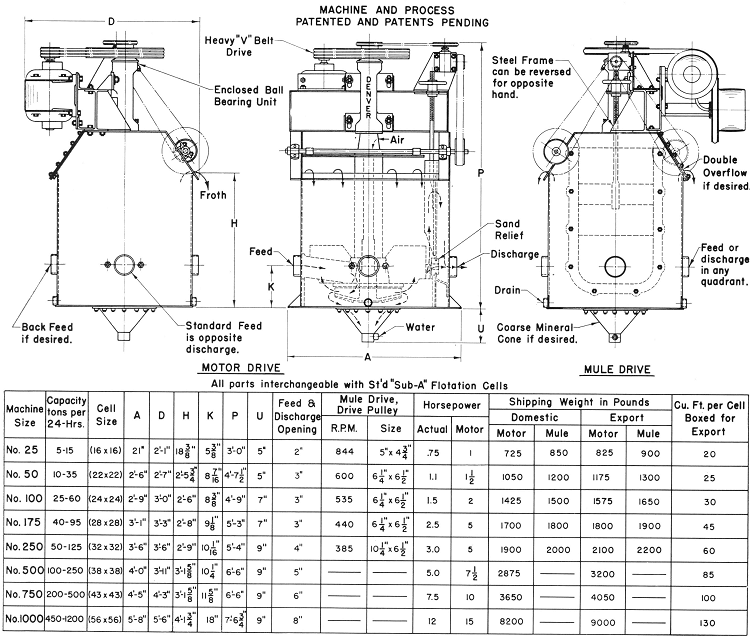
Flash Flotation Cells are built in eight sizes from the No. 25 to the No. 1000. Parts of Flash Cells are interchangeable with the comparable size of standard Flotation Machine. Pressure molded rubber-covered conical disk impellers are standard on all sizes due to the very coarse material handled.
Hand wheel gate weir control is standard on all sizes except the No. 25 which has wood weir blocks. Sand relief openings with rubber inserts are standard on all sizes.
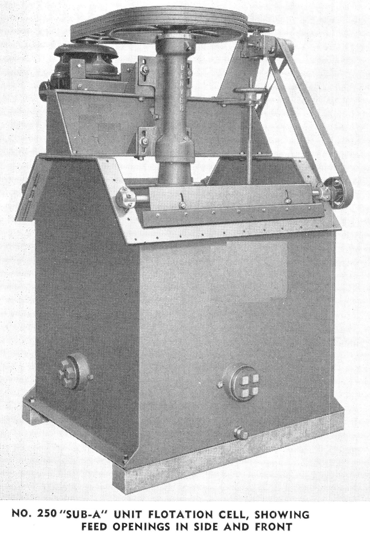
The mineral cone at the bottom of the cell, to entrap coarse mineral and tramp iron, is furnished unless otherwise specified. A plug cock for the cone can be furnished, but is not standard equipment. Two types of drive are available:
- Motor drive with ball bearing motors and V-Belt drives,
- Mule Drive with special round belt running over two idling sheaves to main drive sheave.
The main drive sheave has a crown face built onto it in addition to the V groove, so that it is driven by fiat belt from the main line shaft. This type of drive is not furnished on No. 500, No. 750 and No. 1000 sizes.
Flash Flotation Cells are furnished right hand unless otherwise specified. That is, when standing at the front of the machine, the feed comes in at the left and discharge is at the right. Left-hand units can be furnished. The direction of pulp flow may also be easily changed in the field. Standard feed is from the side of the machine, but all sizes are arranged so that feed may be introduced at the back.
Bottom cell liners are rubber covered and side liners are cast iron. Standard paddle shaft drive is through speed reducer and belt, from impeller shaft sheave. Double overflow machines can be furnished in addition to the standard single discharge cells.
Flash Flotation Cell Capacity

Typical Metallurgical Results With Flash Flotation Cell

PROVED METAL RECOVERY RESULTS
Canada Gold Mill: “Unit Cells making from one to five thousand dollar concentrate, leaving so little in tails that present air cells are unable to produce satisfactory results on tails.”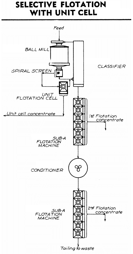
Idaho Lead-Zinc-Iron Ore: “The Flash Flotation Cell is removing direct from the grinding circuit over 70% of the total lead recovered in the entire plant. This phenomenal recovery is made by a Unit Flotation Cell installed between the ball mill and classifier, and a coarse high grade rougher concentrate averaging 65% to 70% lead is obtained without using any depressing reagents to prevent the zinc and iron minerals from floating, and without cleaning.”
In the Philippines: “The No. 250 Flash Cell is fine and makes from 35% to 45% recovery. The classifier overflow remains practically constant regardless of the head. That is, the Unit Cell drops off to 25% on lower grade ore. The interesting point here is, the ratio of concentration for the plant is about .150:1, and with the Flash Cell making a higher grade concentrate than the rest of the circuit, the ratio must be 500:1 or 600:1 showing the ability of the cell even when there are practically no sulphides to float.”
Recovery Losses Reduced 50 Percent: “The average heads are .19 gold, and the ore is very slimy. The tails prior to the installation of the Flash Flotation Cell averaged approximately .015. After the Flash Cell was installed the tails were immediately reduced to .008. The grade of concentrate made is most satisfactory, and the Flash Flotation Cell is doing splendid work.”
Colorado Gold Property: “A Flash Flotation Cell was placed in the ball mill-classifier circuit. The result of this change was the production of a higher grade final concentrate together with a lower final tailing of 0.02 oz. of gold per ton.
“The addition of this Flash Cell to the circuit provided a ‘safety unit’ to absorb ‘peaks’ in grade of the feed and removal of the mineral immediately when freed in the ball mill. The grade was improved by addition of the coarse clean, high grade Flash Cell concentrate to the final flotation concentrate.”
From South America: “Your largest size spiral screen and the Flash Flotation Cell are doing constant and fine work. Neither is used for its generally accepted duty. The screen is high in the building and takes the ball mill discharge from the sand pump, sending oversize back to the ball mill and the screen product to tables and flotation. The Unit Cell is a cleaner and does very nice work.”
Large Gold Concentrator: “The cells recover 60% of the total values by flotation alone. Since the addition of the cones, extraction has increased to 75% and a definite saving has been shown in final flotation tailings.”
California Gold Property: “The Flash Flotation Cell is working in every way quite satisfactorily, and we recover about 50% of our concentrates at this cell, and as yet an undetermined amount of free gold in the hopper attached to the bottom of the cell. At the present time we are recovering about 93% of the values in the ore, and although we are not able to state what increment of extraction over our former is due to the Flash Cell, we do feel that this unit is reflecting itself favourably in this regard.”
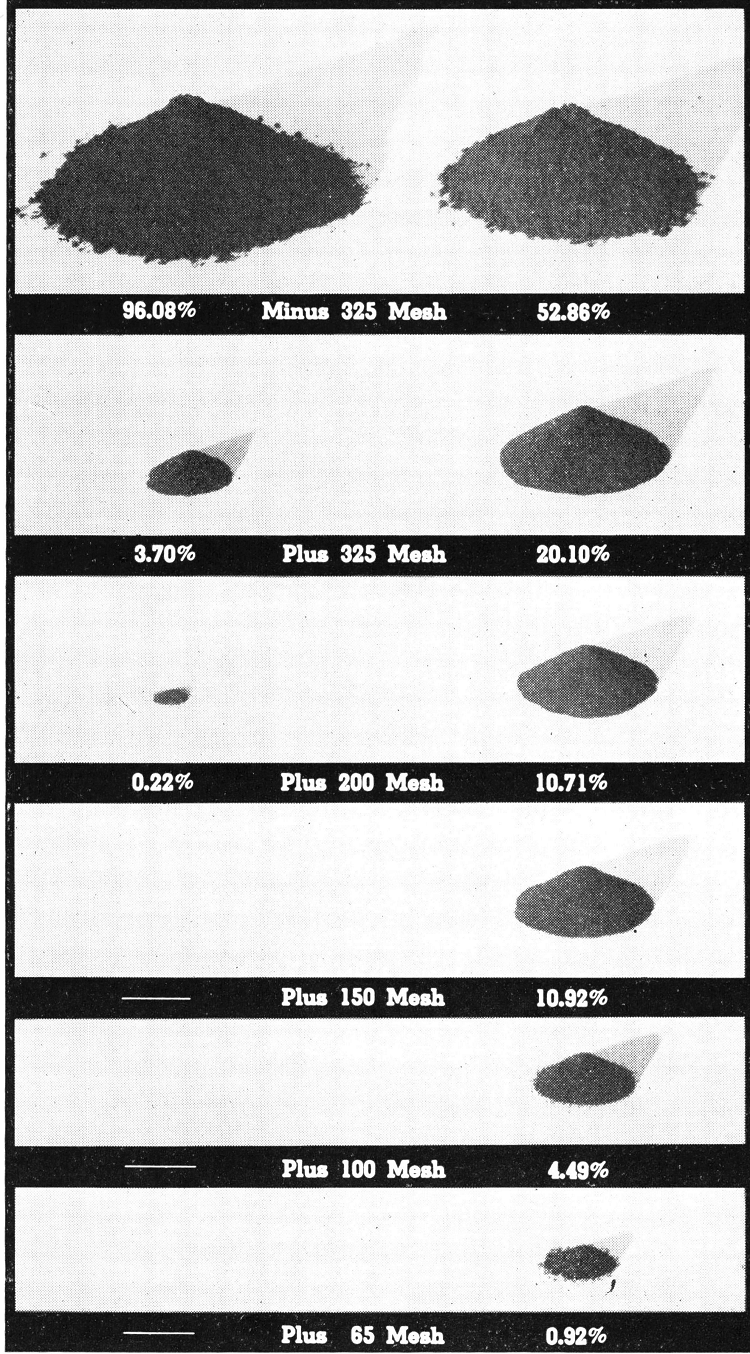
Photographs showing actual products screened from two comparative samples of lead flotation concentrates in parallel circuits. At left, vertically, are the normal products from one circuit. At right are the coarse concentrates obtained from one Flash Flotation Cell between the ball mill and classifier in the parallel circuit.
