Flash Flotation Cell
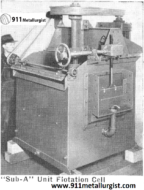
The “Sub-A” Flash Flotation Cell, when installed in the circuit between the ball mill and classifier, makes possible the quick recovery of coarse free mineral, which is a vital factor in economic mill operation. Slime losses from overgrinding are reduced to a minimum with the use of the “Sub-A” Unit Flash Flotation Cell, resulting in increased metallurgical efficiency. Mill costs are lowered due to the fact that this machine provides an efficient means of reducing the load on the mill circuit. When mill heads are a variable factor, as they usually are, this unit provides for a satisfactory method of ironing out these variations, resulting in better mill control. This machine is adaptable to practically any mill circuit and is universally used in the treatment of such ores as copper, lead, zinc, iron, gold, and silver.
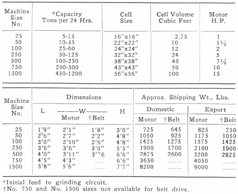
The “Sub-A” Unit Flotation Cell is built in varying sizes to accommodate a large range of tonnage and can be readily fitted to most existing mill circuits. The machine embodies all of the principles of the “Sub-A” Flotation Machine cell, with the addition of the coarse mineral cone on the bottom of the tank, where extremely coarse mineral particles and tramp iron are removed from the mill circuit. The “Sub-A” Unit Flotation Cell is designed so that all parts are interchangeable with the parts of the “Sub-A” Flash Flotation Machine cell of equivalent size. The distinctive gravity flow feature, together with easy and positive adjustment and the use of long-life molded rubber wearing parts, make the unit cell ideal for operation in the grinding circuit, as very coarse material is readily handled. However, there are many other points in circuits where this unit is of great value, such as in scavenger operation.
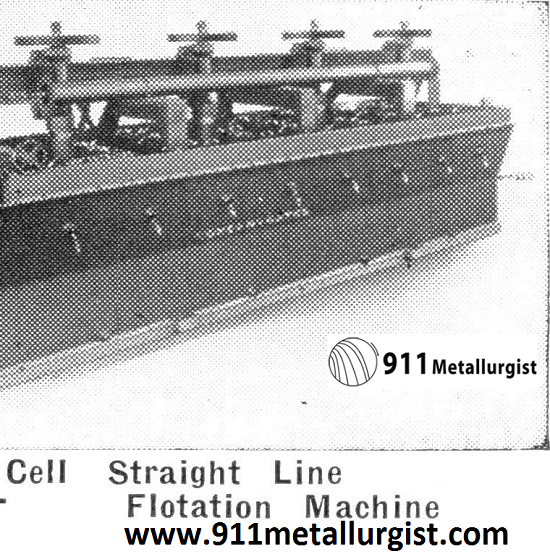
Straight Line Flotation Machine
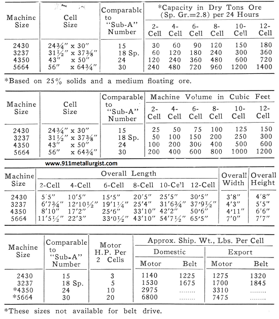
Straight Line Flotation Machine was developed to meet the needs of operating plants having no particular metallurgical problem other than treating large tonnages by bulk flotation. Of particular interest are applications of the machine to the flotation of non-metallics such as coal and phosphates, and low ratio sulfide ores, where quick froth removal is desired.
Outstanding in the design features of the Straight Line Flotation Machine is the possibility of converting the machine to the standard “Sub-A” Flotation Machine, when the occasion arises due to possible varying applications. As compared to the “Sub-A” Flotation Machine, this unit has an open tank, with straight sides (no spitzkasten). Pulp level through the machine is controlled by an adjustable weir arrangement on a maximum of every fourth cell. Thus in every four cells, the only division between cell to cell impeller assemblies is a shallow baffle to prevent froth travel lengthwise through the machine. The depth of the froth bed is controlled by adjusting the height of wood or steel slats on the overflow lips of each cell. The welded steel tank has a lowhead beam mounted on top to carry the shaft mechanisms and motor drives. This allows for the use of the double froth overflow. The tank is reinforced with channels placed so that future conversion to the standard “Sub-A” Flotation Machine is possible by merely bolting the cell partition plates into place and adding the weirs.
The aerating and agitating mechanisms of the Straight Line Flotation Machine are identical to those of the “Sub-A” Flotation Machine. A feed pipe is furnished with every four cells and the feed may enter in any cell. Middling return feed pipes are used for gravity return of those products to any cell. Standpipes to protect the shaft wear and to introduce atmospheric air to the impeller are standard. If additional low pressure air is desired, the standard Supercharging method is readily applied. Rubber bottom liners, cast iron side liners and pressure molded rubber or alloy iron wearing parts are standard.
A low initial cost machine can thus be obtained with simplicity of design and operation. High economic recoveries result from intense aeration, quick removal of froth, high tonnages and low horsepower consumption. Although the two cell V-belt motor drive is preferred, two sizes of this machine are available with belt drive from a jackshaft.
Flotation Cell Capacity
Flotation Machine “Sub-A”
The reliability of the “Sub-A” Flotation Machine is proven by its world wide acceptance and application since 1927. During the intervening years improvements in design have been incorporated to better metallurgical results and, at the same time, structural and wearing qualities have been improved. These changes can be applied to earlier machines at low cost, without difficulty.
The design of the “Sub-A” Flotation Machine incorporates all of the basic principles and requirements of flotation. With its distinctive design, the “Sub-A” Flotation Machine is the only machine that will successfully handle all types of flotation problems. Its wide acceptance in all branches of metallic, non-metallic and industrial flotation is evidence of its basically sound qualities.
“Sub-A” Flotation Cell has many distinctive features which make it the universal flotation unit. These distinctive features are:
- Handles Coarse Material—The patented gravity flow principle assures positive circulation of all pulp fractions. There is no bedding or sanding.
- Aeration Can Be Controlled—For sluggish pulps the supercharging principle can be adapted to any “Sub-A” Flotation Machine to increase the degree of intensity of aeration. Likewise, with this feature the amount of aeration can be decreased when required. With standard operation air is drawn down the stand¬pipe and partition.
- No Short Circuiting—Machine design allows pulp to pass through each and every impeller or a portion to bypass through partition openings. This flexibility gives the operator a unit cell machine, or the “open tank” machine, by a quick adjustment while in operation.
- Middling Return by Gravity—The exclusive “Sub-A” design allows rougher, cleaner, and recleaner products to be returned from one cell to another by gravity, hence no pumps or elevators are required.
- Positive Cell Control—A minimum of operating attention is required as the quick pulp level adjustment keeps the machine in balance for any feed variation. The stationary hood and air standpipe with wearing plate, protect the impeller from sanding and eliminate the necessity for draining machine after shutdown.
- Selectivity—Selective flotation is a noted feature of the “Sub-A” Flotation Machine and is a result of the combination of machine features. The high selectivity, coupled with flotation of coarse as well as fine particles, assures maximum flotation efficiency. Results are a high ratio of concentration, high recovery, low volume of circulating load and improved final product, acceptable for dewatering and subsequent smelting.
Standard “Sub-A” Flotation Machines are built with heavy steel tanks and rigid superstructures. The super¬structure supports the heavy duty shaft assemblies in their individual, totally enclosed, bearing housings. The cells are protected against wear by cast iron side liners and rubber bonded to steel bottom liners. The wearing parts can be either alloy iron or pressure molded rubber. The pressure molded rubber wearing parts are a distinct feature of “Sub-A” Flotation Machines. This type of construction has been applied to “Sub-A” Flotation Machines since 1932 and is used for impellers, wearing plates, and replaceable sand relief bushings. The impeller shafts are protected by means of rubber shaft sleeves.
Pulp level control is by means of conveniently located extra-wide weirs which are adjustable with either hand¬wheel gate, gear gate, or wood weir blocks. These easily adjusted weirs control the pulp level, and froth removal is facilitated by froth paddles.
“Sub-A” Flotation Machines are furnished with either V to V heavy duty drives from vertically mounted ball bearing motors, or with the belt drive type in the smaller size machines. Standard belt drives are quarter twist V belt to grooved pulley lineshaft for multi-cell installations.
Recent improvements can be adapted to the earlier “Sub-A” Flotation Machines and, if required, the hand of the machine can be reversed in the field.
“Sub-A” Flotation Machines are moderately priced, due to standardization and quantity production. Specifications are varied to suit particular conditions and special features are added to the machine at slight additional cost. Every machine is factory assembled and carefully labelled, to facilitate quick and accurate re-assembly in the field. Assembly details are furnished with every order.
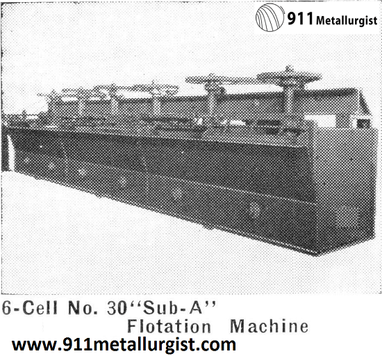
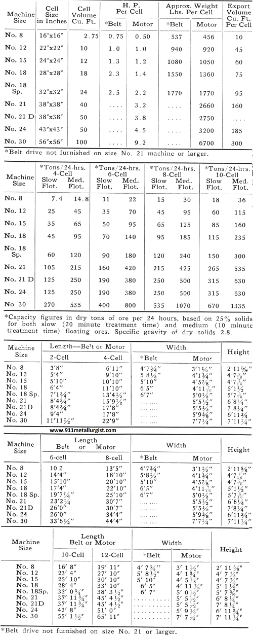
Flotation Cell Capacity
Flotation Bank
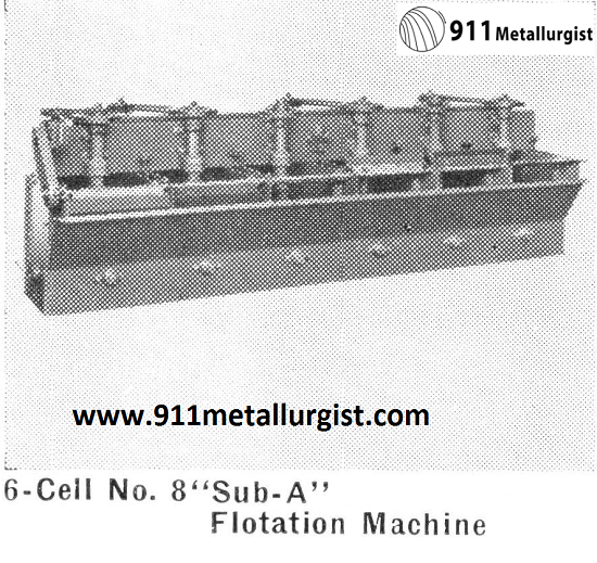
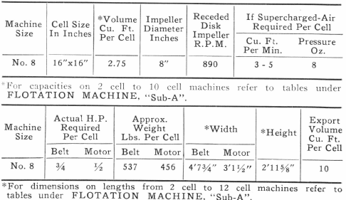
Flotation research can be conducted continuously and economically with the No. 8 (16″x 16″) “Sub-A” Flotation Machine. Built with all the attributes of the large commercial machines, it is sufficiently small (500 to 1500 pounds an hour) to develop new control and research flowsheets.
Large concentrators now in operation can run this small continuous commercial machine in parallel with standard units. New processes can be developed and placed in production on small tonnages in chemical plants. Pilot plants can operate 24 hours a day on concentration problems requiring lengthy study, or to recover by-product material.
This machine has all the distinctive features of the larger machines, including the famous gravity flow principle. The welded steel tank is protected by rubber bottom liners and cast-iron side liners. Individual cell control is obtained by either wood weir blocks or hand-wheel operated steel gates. Sand relief openings, froth paddles, and hard-iron receded disk impellers and diffusers are standard. Controlled aeration with supercharging is provided.
Source: This article is a reproduction of an excerpt of “In the Public Domain” documents held in 911Metallurgy Corp’s private library.
