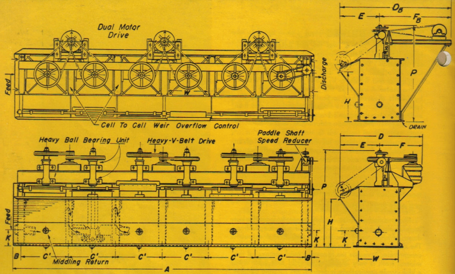
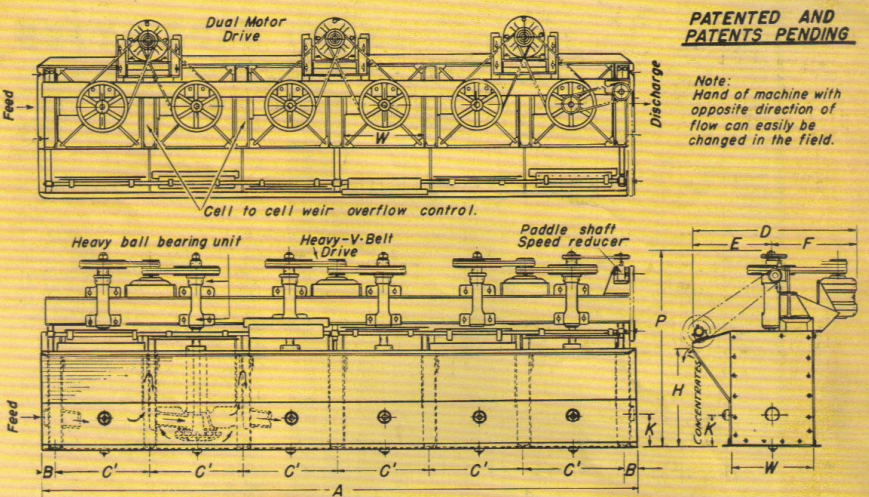
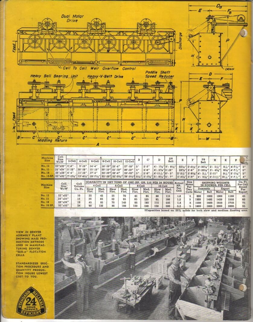
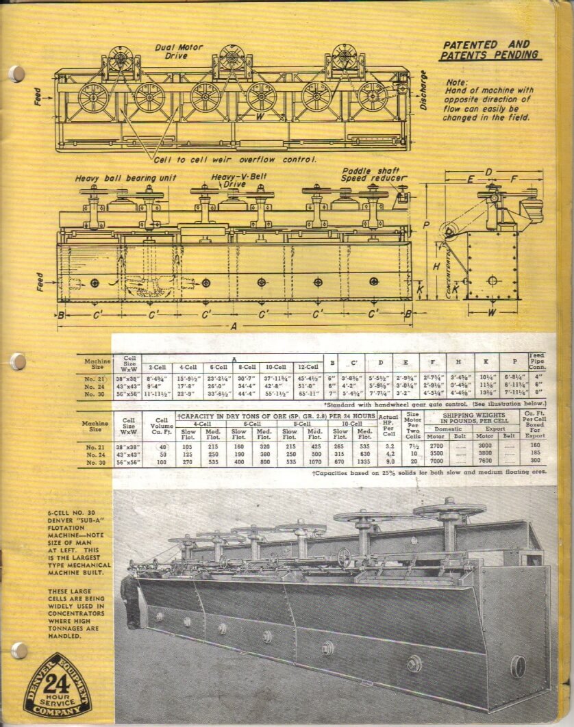
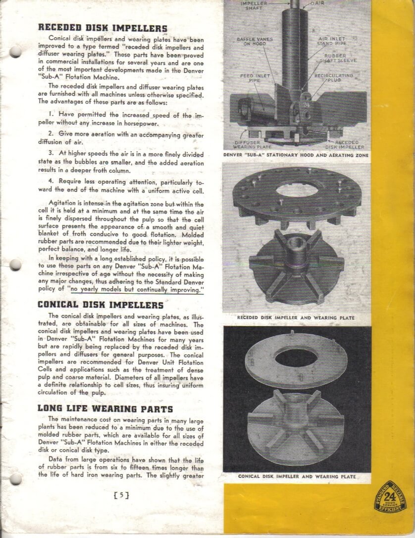
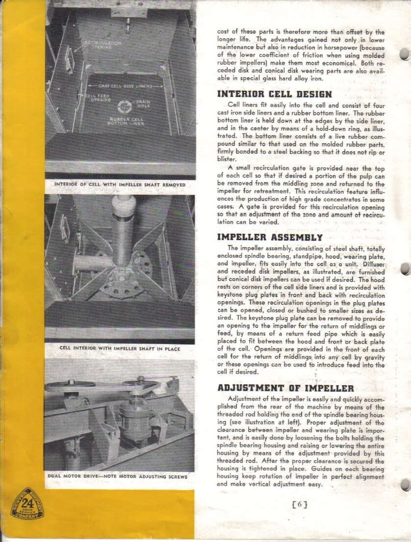
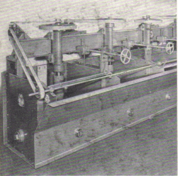
 The task for the “Sub-A” Flotation Machine-Cell design is solid as it is made of heavy steel joints are electric welded both inside and out. Partition plates are furnished with gaskets and arranged for bolting to partition channels so that if necessary all of the plates can be changed at any time in the field to provide either a right or left hand machine. Right hand machine is standard and will be furnished unless otherwise noted.
The steel superstructure for mounting the shaft assemblies consists of a heavy structural steel member rigidly braced and arranged so that minimum headroom is required. Proper design positively minimizes vibration in operation, and construction of the machine as a self-contained unit eliminates the necessity for any costly or elaborate foundation.
“Sub-A” Flotation Machines are also available in wood tank construction, especially suitable for corrosive circuits. These machines can be supplied with modifications so that they are ideal for use in special applications.
All cells are placed at a common floor level and due to the gravity flow principle of “Sub-A” Flotation Machines almost any number of cells can be used in any circuit at one elevation without the necessity of pumps or elevators to handle the flow from one machine to the next. Operation and supervision is thus simplified. For export shipments all of the items for the flotation machine are packed, braced and blocked inside of the steel tank so that minimum volume is required. Safe delivery of parts without damage is thus assured.
BEARINGS AND HOUSING: The shaft and impeller of the “Sub-A” are supported in an enclosed ball bearing housing designed to properly carry and maintain the rotating impeller. Both the upper and the lower heavy duty, oversized, anti friction bearings are seated in the housing, insuring perfect alignment and protection against dirt. Bearings have grease seals to prevent grease or oil getting into the cells; lubrications is only needed about once in six months. Over twenty thousands of these standards bearings are in daily use on “Sub-A” Cells, giving continuous service and low horsepower.
STATIONARY HOOD: The hood, which located near the bottom of the cell, it is an important part of the assembly as it serves a number of purposes. The vanes on this hood prevent swirling of the pulp in the cell, producing a quiet action in the central or separation zone. The hood also supports the stationary standpipe and the hood wearing plate. Sufficient air for flotation is drawn down the stationary standpipe which eliminates the expenses of blowers, air-pipes, and valves, as well as giving direct passage of air to the top of the rotating impeller. The wearing plate is bolted to the bottom of the hood and prevents the impeller from being buried by pulp when the machine is shut down.
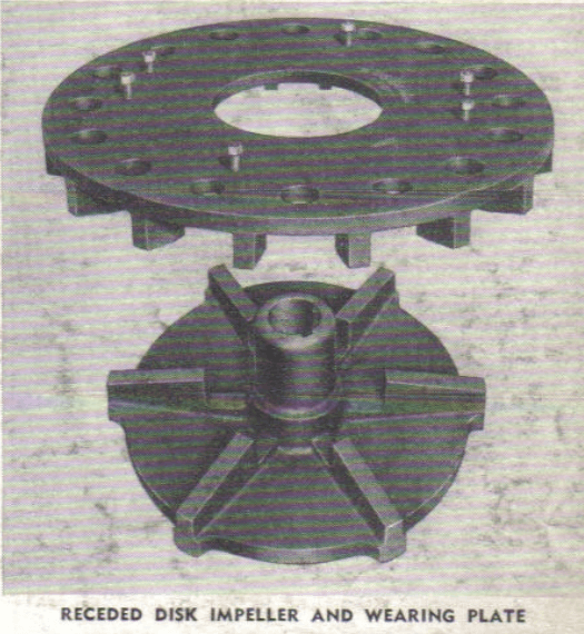
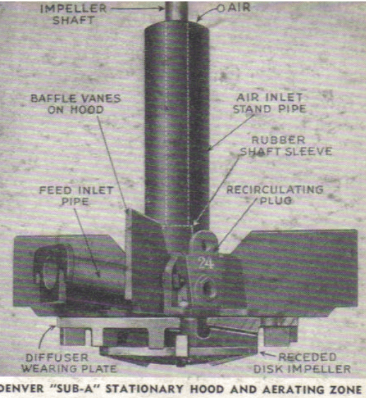 RECEDED DISK IMPELLERS: Conical disk impellers and wearing plates have been improved to a type termed “receded disk impellers and diffuser wearing plates.” These parts have been proved in commercial installations for several years and are one of the most important developments made in the “Sub-A” Flotation Machine.
The receded disk impellers and diffuser wearing plates are furnished with all machines unless otherwise specified. The advantages of these parts are as follows:
- Have permitted the increased speed of the impeller without any increase in horsepower.
- Give more aeration with an accompanying greater diffusion of air.
- At higher speed the air is in a more finely divided state as the bubbles are smaller, and the added aeration results in a deeper froth column.
- Require less operating attention, particularly toward the end of the machine with a uniform active cell.
Agitation is intense in the agitation zone but within the cell it is held at a minimum and at the same time the air is finely dispersed throughout the pulp so that the cell surface presents the appearance of a smooth and quiet blanket of froth conducive to good flotation. Molded rubber parts are recommended due to their lighter weight, perfect balance, and longer life.
In keeping with a long established policy, it is possible to use these parts on any Denver “Sub-A” Flotation Machine irrespective of age without the necessity of making any major changes, thus adhering to the Standard Denver policy of “no yearly models but continually improving.”
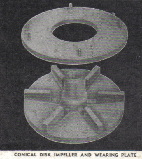 CONICAL DISK IMPELLERS: The conical disk impellers and wearing plates, as illustrated, are obtainable for all sizes of machines. The conical disk impellers and wearing plates have been used in Denver “Sub-A” Flotation Machines for many years but are rapidly being replaced by the receded disk impellers and diffusers for general purposes. The conical impellers are recommended for Denver Unit Flotation Cells and application such as the treatment of dense pulp and coarse material. Diameters of all impellers have a definite relationship to cell sizes thus, insuring uniform circulating of the pulp.
LONG LIFE WEARING PARTS: The maintenance cost on wearing parts in many large plants has been reduced to a minimum due to the use of molded rubber parts, which are available for all sizes of “Sub-A” Flotation Machines in either the receded disk or conical disk type.
Data from large operations have shown that the life of rubber parts is from six to fifteen times longer than the life of hard iron wearing parts. The slightly greater cost of these parts is therefore more than offset by the longer life. The advantages gained not only in lower maintenance but also in reduction in horsepower (because of the lower coefficient of friction when using molded rubber impellers) make them most economical. Both receded disk and conical disk wearing parts are also available in special glass hard alloy iron.
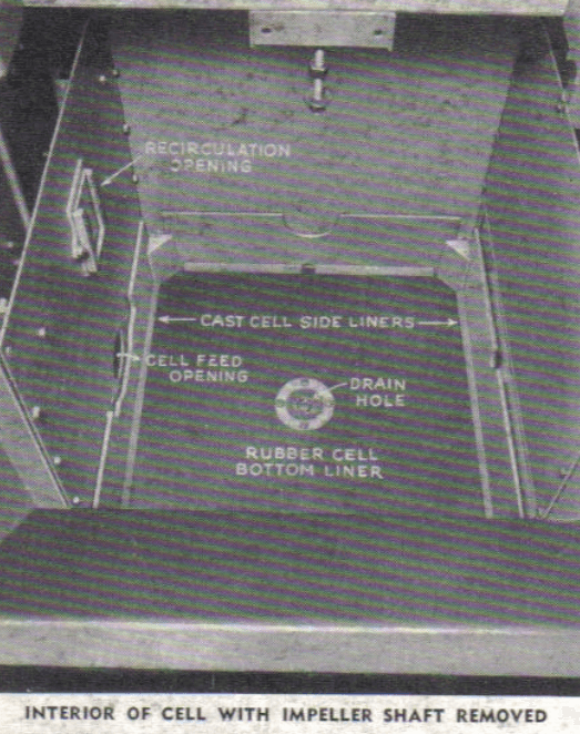 INTERIOR CELL DESIGN: Cell liners fit easily into the cell and consist of four cast iron side liners and a rubber bottom liner. The rubber bottom liner is held down at the edges by the side liner, and in the center by means of a hold-down ring, as illustrated. The bottom liner consists of a live rubber contrasted similar to that used on the molded rubber parts, firmly bonded to a steel backing so that it does not rip or blister.
A small recirculation gate is provided near the top of each cell so that if deserved a portion of the pulp can be removed from the middling zone and returned to the impeller for retreatment. This recirculation feature influences the production of high grades concentrates in some cases. A gate is provide for this recirculation opening so that an adjustment of the zone and amount of recirculation can be varied.
IMPELLER ASSEMBLY: The impeller assembly, consisting of steel shaft, totally enclosed spindle bearing, standpipe, hood, wearing plate, and impeller, fits easily into the cell as a unit. Diffuser and receded disk impellers, as illustrated, are furnished but conical disk impellers can be used if desired. The hood rests on corners of the cell side liners and is provided with keystone plug plates in front and back with recirculation openings. These recirculation openings in the plug plates can be opened, closed or bushed to smaller sizes as desired. The keystone plug plate can be removed to provide an opening to the impeller for the return of middlings or feed, by means of a return feed pipe which is easily placed to fit between the hood and front or back plate of the cell. Openings are provided in the front of each cell for the return of middlings into any cell by gravity or these openings can be used to introduce feed into the cell if desired.
ADJUSTMENT OF IMPELLER: Adjustment of the impeller is easily and quickly accomplished from the rear of the machine by means of the threaded rod holding the end of the spindle bearing housing (see illustration at left). Proper adjustment of the clearance between impeller and wearing plate is important and easily done by loosening the bolts holding the spindle bearing housing and raising or lowering the entire housing by means of the adjustment provided by this threaded rod. After the proper clearance is secured the housing is tightened in place. Guides on each bearing housing keep rotation of impeller in perfect alignment and make vertical adjustment easy.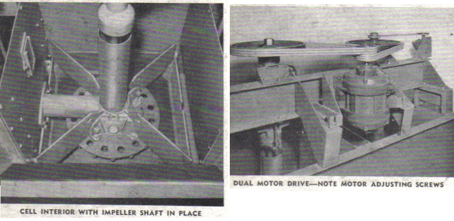
TYPES OF DRIVES: The “Sub-A” was the first flotation machine to use the Multi-V-Belt Horizontal Drive, which has proved so successful. “Sub-A” (Fahrenwald) Flotation cells have been carefully designed to be driven either by a motor and V-belts or by V-belt to a main drive shaft. In the motor driven type the impeller shafts are driven by V-belts, sheaves and vertical ball bearing motor. This type of drive is much more economical and desirable than a direct motor driven unit because it makes any speed range available and does not require a special motor shaft assembly.
The standard drive on all flotation machines of an even number of cells is one motor driving two cells through V-belt drives. If an odd number of cells is ordered, a drive which will prove most economical in first cost and provide the greatest operating efficiency, will be furnished. Adjustment of belt tension is provided for in the motor mounting (see illustration at bottom of opposite page.)
FROTH PADDLE-SHAFT DRIVE: The paddle shaft drive is taken generally from the last impeller shaft by means of V-belt drive to a speed reducer, which in turn drives the paddleshaft at slow speed. The quick removal of the mineral froth, in the form of a concentrate, increases the recovery: quick removal of this mineral froth is very important on gold ores, and when a high grade concentrate is desired, the rotating paddles can be regulated to the desired radius.
POSITIVE PULP LEVEL CONTROL
Every “Sub-A” Cell is actually an individual flotation machine with its own pulp level, controlled by its weir overflow. Correct flotation requires this positive pulp level control in each cell even though this adjustment when once made is infrequently changed. There are three methods of regulating the pulp level: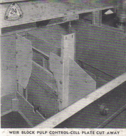
WEIR BLOCKS, as illustrated slide easily into place at the weir, and consist of wood slats held down by means of a steel wearing bar. On the smaller machines especially, adjustment by this means is easy as the weir is readily accessible. Actual plant practice shows in the normal circuit that it is not necessary to change the pulp level frequently.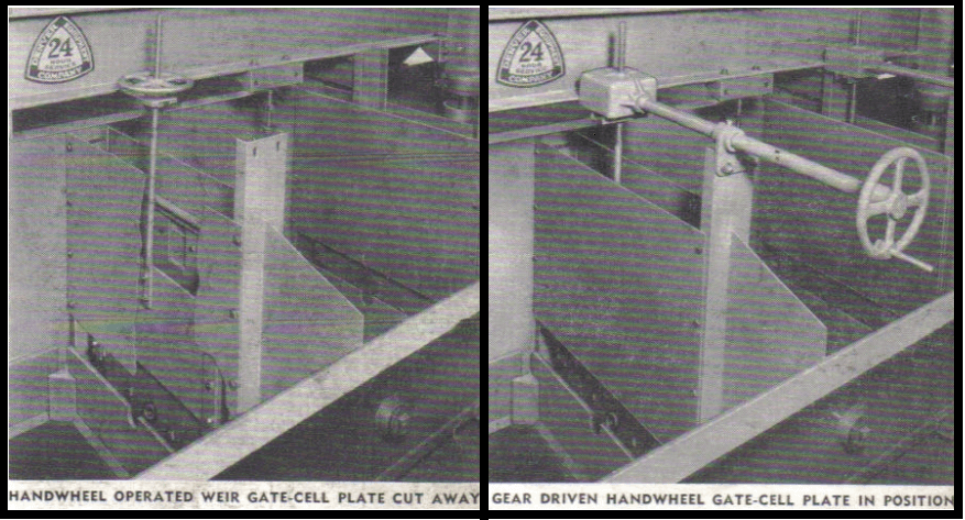
HANDWHEEL OPERATED WEIR GATES can be provided, as illustrated, so that changes in pulp level in each individual cell can be accomplished by turning the handwheel which is located far above the froth level. Changes in level can be made quickly and easily with minimum effort.
GEAR DRIVEN HANDWHEEL GATES as illustrated, can be provided and are especially useful on larger size flotation machines. This arrangement brings the control of the pulp level out to the front of the machine making it unnecessary to reach over the froth lip. The use of a gearbox with handwheel control reduces the effort required for raising or lowering the gate, and provides a method of quick and easy adjustment.

