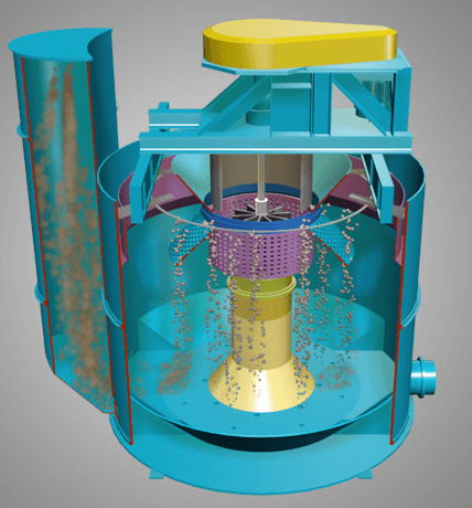
 In preparation for this EXAMPLE Startup, the following items must be checked before the associated conditioning and flotation equipment and circuit is started.
- Ensure that all applicable reagent systems are operational, and that the conditioning tank agitators, flotation feed pumps, flotation mechanisms, flotation blower, and the rougher concentrate, cleaner tails, and argentite leach feed pumps are operational.
- The samplers should have plant air, and should be ready to operate.
- Fresh gland seal water must be available for the flotation feed pumps and the conditioning agitators.
- Select which flotation feed pump will operate, and check that it’s suction line is not sanded.
Start UP Sequence
Under normal operating conditions the conditioning tank agitators and flotation cell mechanisms will run continuously.
- Start up can commence when the condition feed pumps from the filtration circuit begin delivering slurry to this circuit.
- Turn on gland seal water to the conditioning tank agitators and the flotation feed pumps,
- Turn on the conditioning tank exhaust fans.
- Open plant air valves to allow sparge air to the conditioning tanks; adjust flow to 100 cfm using the rotameters for each tank.
- When the slurry level in the first conditioning tank is above the agitator blades, the agitators can be started.
- Start the sodium metabisulphite metering pump and begin adding sodium metabisulphite to the first conditioning tank.
- Start the lime timer and open the diaphragm valve to allow lime into the first conditioning tank. Monitor pH during start up, and if necessary open the diaphragm valve in the lime line to the second conditioning tank. The lime timer may be adjusted for fine tuning the lime addition.
- Start flotation reagent addition (Xanthate, A-208, sodium silicate, and copper sulphate) to the second conditioning tank.
- When the slurry overflows into the second conditioning tank discharge compartment, start the flotation feed pump.
- Open the air valve to sampler and start the sampler timer.
- Start all flotation mechanism drives (rougher and cleaner), and open both plug valves at the junction and discharge boxes of the rougher cells.
- Start the flotation blower, and open all air valves to each flotation mechanism (rougher and cleaner).
- Start the rougher concentrate pump, cleaner tails pump, and the Argentite leach pump.
- Start the sampler timer.
- Turn on the reclaim water spray to all flotation launders.
Normal Operation
After the Conditioning and Argentite Flotation Circuit has been brought up to normal operating conditions, the operator must monitor the various process variables and alarms. The operator is also required to sample and analyse process streams and monitor local indicators.
The operator must monitor the reagent and air flowmeters to the first and second conditioning tanks. The reagent and air flowrates must be adjusted to give the optimum cyanide destruction and flotation conditioning results.
The pH in the second conditioning tank must be monitored regularly to ensure that a pH of 8.0 is maintained. Adjust the lime timer accordingly to increase or decrease the pH.
NOTE: The conditioning tanks must never be operated without their respective exhaust fans running.
One of the most important functions of the flotation operator is to ensure that the optimum pulp level in all flotation cells is maintained. A low pulp level will result in poor Argentite recovery while a high pulp level will result in a poor Argentite concentrate grade. The pulp level in the rougher cells is controlled by manually adjusting the dart valves in the junction and discharge boxes. The pulp level in the cleaner cells is controlled by raising or lowering the tailings weir gate at each cell.
The operator must monitor the air flow rate into all flotation cells. Each rougher cell should be supplied with 100 cfm air and each cleaner cell with 30 cfm air.
The pulp density in the flotation cells should be checked manually on a regular basis. The densities should be approximately 25% solids. Adjust the launder spray water accordingly to maintain the proper density.
Flotation reagent addition points are provided to the second conditioner, the rougher feed well, the rougher junction box and the first cleaner feed well. The operator must control the amount of reagents being added and determine the optimum location for reagent addition. The operator can adjust the reagent flow rates with the appropriate, locally mounted, flowmeters.
Normal Shutdown Sequence
When feed to the Conditioning and Flotation Circuit has stopped:
- Discontinue reagent addition to both conditioning tanks and air addition to the first conditioning tank.
- Leave conditioning tank agitators, and exhaust vent fans running.
- When slurry has stopped overflowing into the second conditioning tank discharge compartment, and the discharge compartment has been pumped dry, shut off the flotation feed pump.
- Discontinue reagent and air addition to all flotation cells.
- When the pulp level in all cells drops, shut off launder spray water and close the dart valves in the rougher cell discharge box.
- Leave all flotation mechanisms running but shut off the rougher concentrate pump, the cleaner tails pump, and the Argentite leach feed pump.
Emergency Shutdown
In the event of an emergency, all equipment in the Conditioning and Flotation Circuit can be shut down by locally mounted STOP switches or from the MCC located in the mill control room.
After the equipment is shut down, shut off all reagent metering pumps feeding this circuit and close all air line shut off valves to the conditioning tanks, flotation cells and samplers.
https://www.911metallurgist.com/silver-mineral-argentite-flotation-circuit
https://www.911metallurgist.com/silver-flotation-concentrate-leaching-filtration-circuits
