Design Study for 400-Ton per Day Flotation Plant
The sulphur mill was designed for best adaptation to the mill site available. The design provided for simplicity of construction and final operation, and full usage of construction items available.
Process FLOWSHEET
The flowsheet was based on laboratory tests wherein troublesome factors were eliminated ahead of design and construction. The flowsheet provides for the unit arrangement of equipment and for added flexibility. Two-stage closed circuit crushing (with an apron feeder for control to the jaw crusher), provides —½” ore for grinding circuit. Crushed material is conveyed to a screen and the oversize is returned to the secondary cone crusher. The screened fraction drops to a reversible conveyor, thence to fine ore bins.
Adjustable stroke belt ore feeders regulate the feed to two 5′ x 10′ Steel Head, Ball Mills, in a closed circuit with Cross-flow Classifiers. Each classifier discharge flows by gravity to two banks of 6 Cell No. 18 Sp. “Sub-A” Flotation Machines. The grind, — 65 mesh is held as coarse as possible to reduce grinding costs and still attain maximum recovery. Each flotation section provides six cells for roughing and three cleaning stages with provisions for elimination of one or more stages for cleaning when the type of ore permits (flexibility incorporated in “Sub-A” Machines).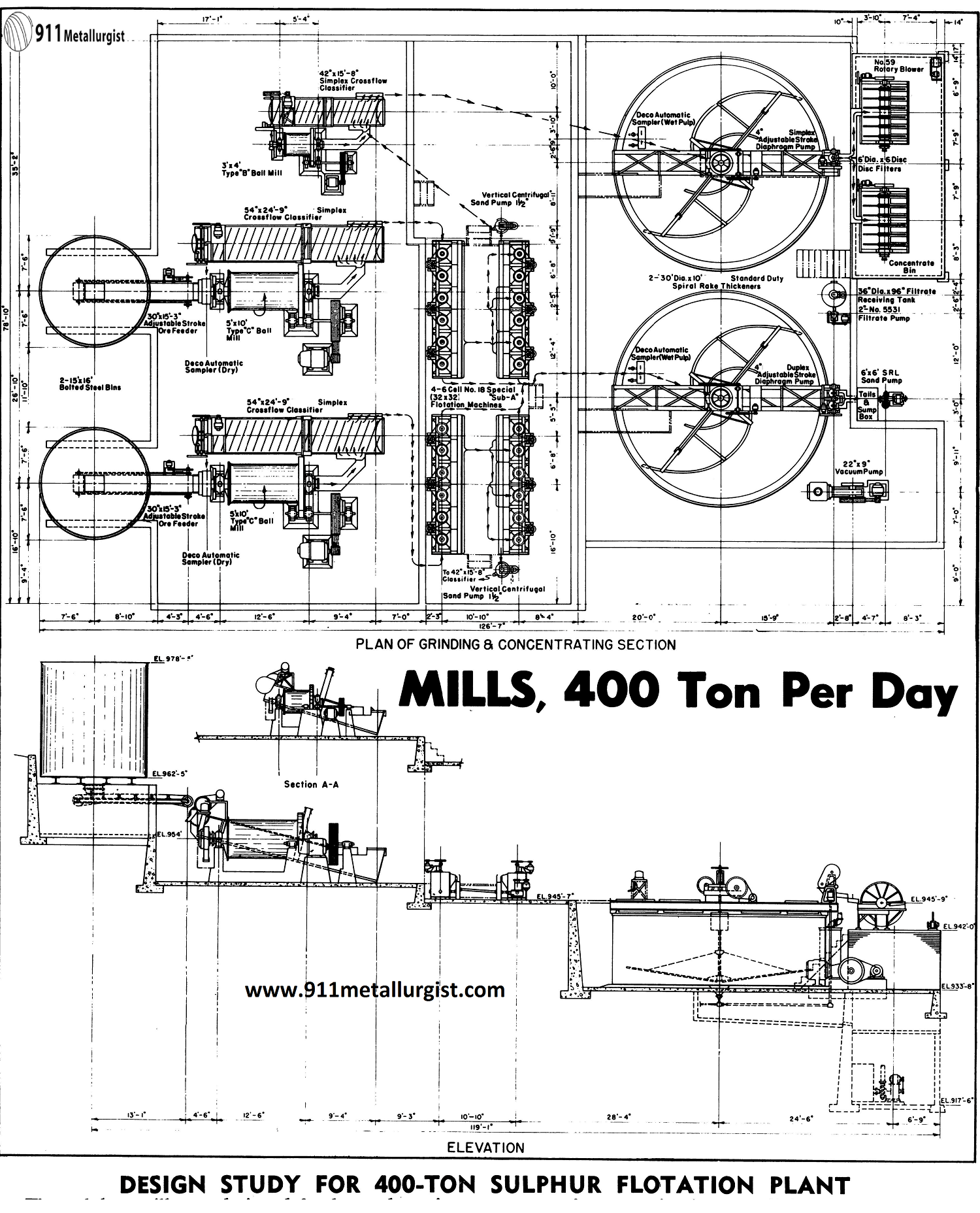
The flotation concentrates are pumped to a regrind circuit to produce desired final size meeting specifications. The final ground concentrates are thickened and filtered. Filters are directly above concentrate storage bins.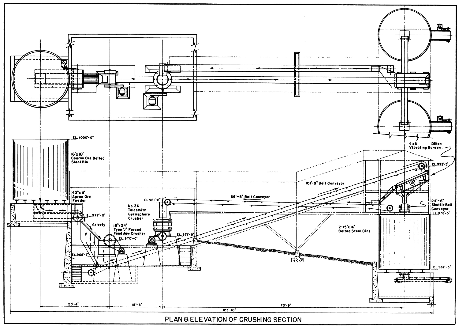
Concentrator MILL SITE
The mill site near the mine is accessible to water, power, labor and supplies, and includes adequate space for expansion and tailings disposal. The topography makes gravity flow through the mill possible and allows for delivery of ore direct from mine cars to mill.
MILL DESIGN AND CONSTRUCTION FEATURES
The mill was planned to minimize the amount of excavation, reduce the height of retaining walls and amount of climbing by mill operators.
Equipment selected gives simplicity and flexibility in operation and allows for changes in tonnages and character of ore. Due to class of labor available, complicated controls and adjustments were eliminated where possible. The machinery selected and installed permits duplication of units for expansion.
As field welding was not available, bolted steel ore bins were installed. The machinery foundations, building foundations, retaining walls and floors are concrete. The flotation machines are mounted on low piers to allow for drainage. An operating platform of wood was installed between flotation machines to give clear working space. The flotation machine launders were designed to permit changes in cleaning stages without shut-downs or prolonged delays, and permits circuit adaptation to changes in ore characteristics. A tailings thickener permits partial reclaiming of water, in dry seasons.
Ore tests and direct planning resulted in reduced initial plant construction and operating costs. The results obtained are proven by owner satisfaction.
Design Study for 75-TPD Flotation Mill
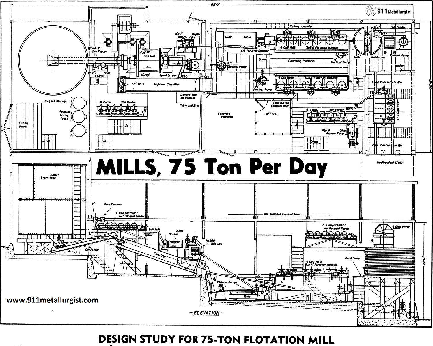
The correct design of a milling plant can mean its success or failure when in operation, the difference between profit and loss. Maximum metallurgical results with low operating and maintenance costs requires thorough study and sound planning. Selection of equipment and construction features must be balanced with available finances and a minimum sacrifice in operating efficiency. Here is a typical small plant where proper design resulted in a successful operation.
Plant Flowsheet
This 75-ton, lead-zinc-gold-silver mill was based on a flowsheet developed through batch and continuous laboratory tests. These studies showed single stage crushing and grinding to 65 % minus 65 mesh was adequate for this operation. Tests indicated that over 70% of the gold, 40% of the silver and 60% of the lead was recoverable in the grinding circuit. Therefore Unit Cell and a Mineral Jig section were installed. Adequate flotation capacity to selectively float the lead and zinc was provided, together with a small concentrating table to visually show results of flotation. The zinc and lead concentrates are pumped v direct to a 4-foot by 4-disc Filter with two compartments. This filter was placed on top of the concentrate bin which location provides desirable operating room around the filter and could be seen from almost anywhere in the mill. The concentrate bins were of laminated wood construction—sturdy and inexpensive. Filtered concentrates drop directly into the bins.
Thickeners were eliminated due to initial installation expense and extra housing required because of climate. Low dilution, by keeping sprays in flotation launders to a minimum and ability of Vertical Pump to handle frothy pulps makes this possible.
Mill Site
The mill site was selected several miles from the mine at a point where water, power and tailing disposal area were available, and where it was accessible even during the heavy snow season. The site is on a natural slope, permitting gravity flow in the mill with minimum pumping requirements.
Mill Design
Equipment is arranged as compactly as possible without crowding and without sacrifice of working space, in order to keep the mill building to minimum size. This keeps capital investment low, and reduces heating costs during cold weather. The mill building, of wood construction with laminated wood roof trusses with one-quarter pitch, was covered with insulating material and corrugated sheet material. This construction was most suitable due to the climate and
low cost of lumber in the area. A small steam boiler and unit heaters were installed for heating. Mill and crushing buildings are on concrete foundations extending about four feet below the ground line. Concrete floors of 4″ to 6″ thick are sloped ¼” per foot, permitting slushing down with a hose.
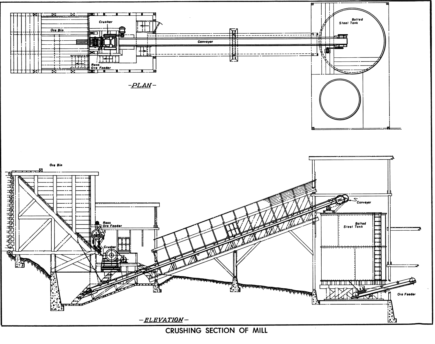
The coarse ore bin was designed for construction from local timber, and provided with a rail grizzly spaced to 8″ to allow manual breakage of oversize.
In the crushing section a wedge bar grizzly was placed ahead of the crusher to remove undersize. A Chain Feeder was installed for control of the coarse ore to the crusher.
Crushed ore conveyor is enclosed in a conveyor¬way for weather protection. Fine ore bin is housed within the mill building to prevent freezing. An inclined belt feeder with variable speed drive gains elevation to grinding mill. Feeder was designed with sloping hopper to reduce load on the belt of feed discharging from the bin.
Foundation for Ball Mill was made of reinforced concrete and cast in one section to prevent distortion and misalignment due to possible settlement or shifting of the foundation. Ball mill, unit flotation cell, jig, and classifier were arranged for easy access and operation. The ball mill was equipped with a spiral discharge screen to remove oversize material ahead of unit cell and jig. The 30″ spiral classifier was equipped with a rotating motor-driven paddle to remove troublesome wood chips from classifier overflow screen.
The two six-cell No. 18 (28×28) “Sub-A” Flotation Machines were elevated on timber bents with operating platforms between the machines; this gave space below machines for pipe lines, launders and concentrate pumps. Reagent feeders were grouped together above flotation machines and conditioners at elevation of filter floor for gravity flow of reagents, and for accessibility.
The mill control office located in the center of the mill, was designed with large windows so almost every machine in the mill could be seen. Operating floors most frequently used were kept as nearly as possible on the same level to reduce stair climbing for the operators. Mill was designed so two men per shift could handle this plant very well.
A gallery was provided in the trussed-roof section, the length of the building, for the installation of main electrical circuits, safety switches, and magnetic motor controls. This kept most of the electrical items away from splash and dirt. All wiring was selected oversize to reduce voltage drop, giving higher operating efficiency and reduced electrical maintenance. Totally enclosed motors were used for reduced maintenance. Push button start-stop controls were placed at the machines and in the mill control office, so that any machine could be controlled from either place.
This practical design provided continuous, troublefree operation with a small operating force. Remote location made it highly essential to eliminate any foreseeable sources of trouble and delays.
Design Study for 500-Ton/Day Flotation Mill
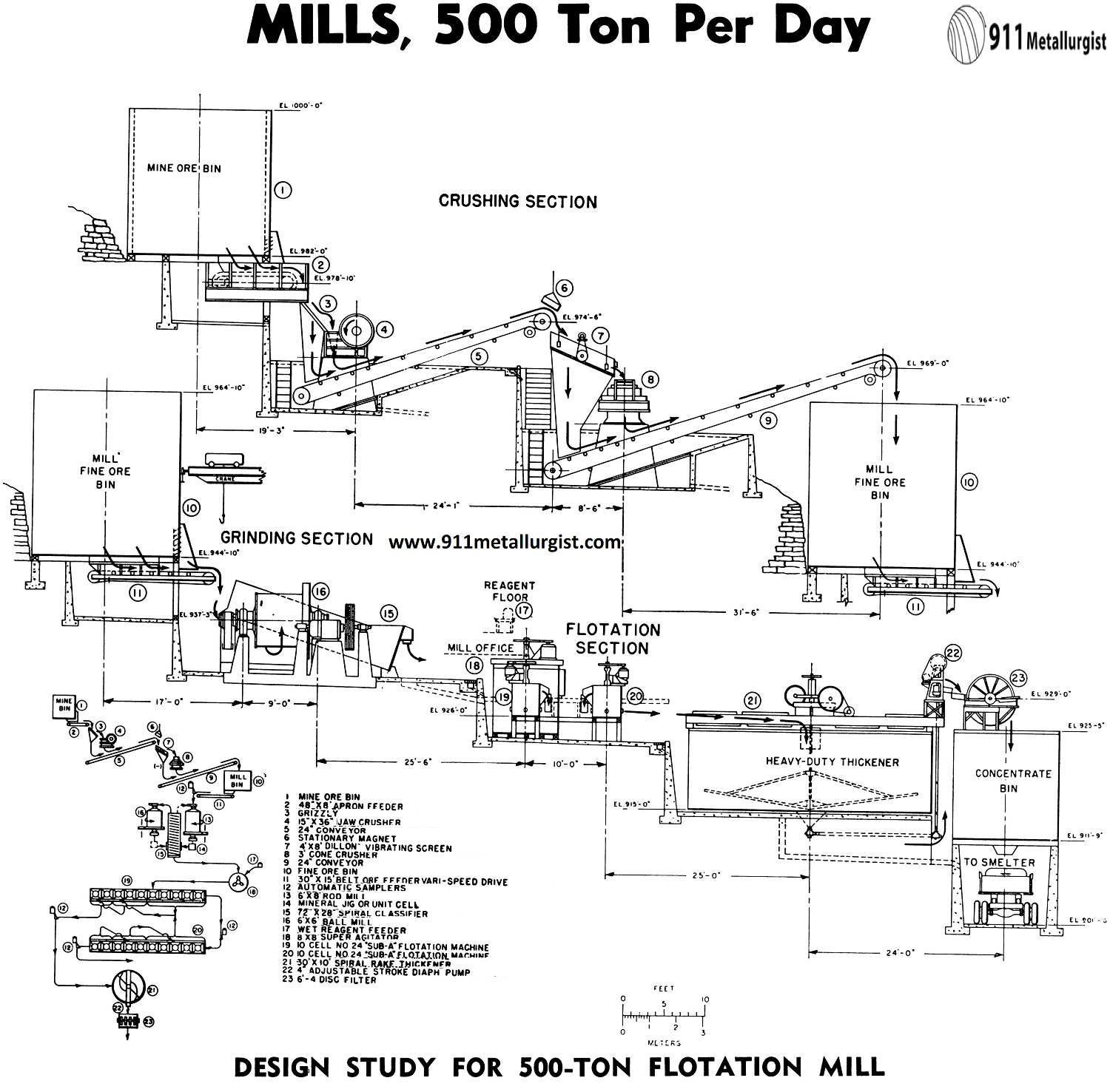
A typical problem confronting a mining operation of moderate production is how to design a mill at a reasonable cost incorporating modern equipment and essential basic principles of materials handling with the minimum construction and mill costs.
Process Flowsheet
The first step in mill design is the flowsheet based on reliable ore tests.
The mill capacity and equipment sizes as shown has been selected as an example for treating 500-550 short tons of ore per 24 hours per day. Two-stage grinding is to all minus 65 mesh for an average ore. Sufficient flotation capacity is included for a medium to slow floating ore. Thickening and filter capacity is selected for a 10 to 1 ratio of concentration as would be the case when treating a 3% copper ore with the copper mineral being chalcopyrite. In such case it would be necessary to filter 50 to 55 tons of concentrates each day. The use of a mineral jig or flotation unit cell in the grinding circuit is recommended. A simple test in our laboratory can tell you whether a coarse product can be recovered easily in the mill circuit.
Mill Design
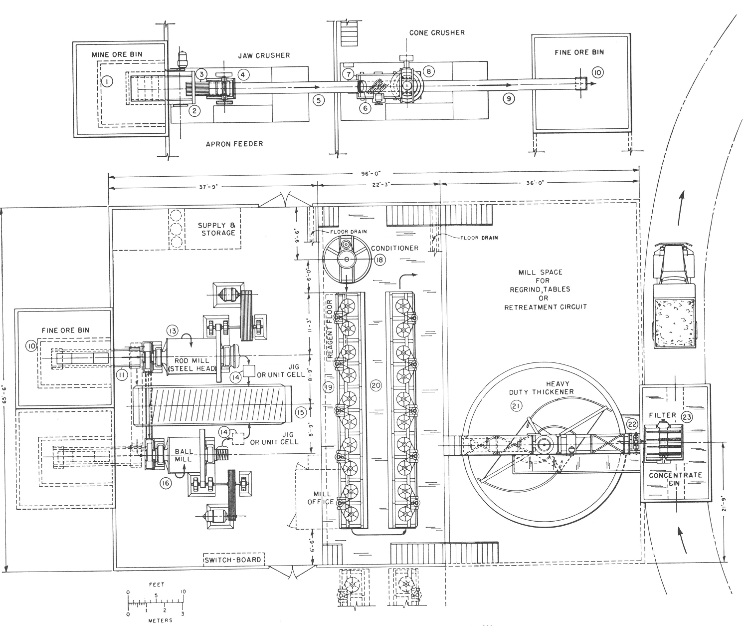
The general design will apply to other ores with slight modification. The arrangement provides for ultimate use of gravity flow as is noted by the absence of pumps and elevators. The basic machines in plan and elevation are shown along with a flowsheet of the crushing, grinding and mill recovery circuits.
Crushing—Two Stage Open Circuit
Mine run ore is fed to the primary jaw crusher by a heavy duty apron ore feeder over a grizzly. Crushed ore from the primary crusher is fed over a vibrating screen ahead of the cone crusher to remove fines. The crushing plant is normally designed to crush the entire daily mill tonnage in one shift or, at the most, 2 shifts.
Grinding—Two Stage Rod and Ball Milling
Two- stage grinding provides the grinding economies outlined in DECO Bulletin B2-B13. In the wet grinding circuit, a rod mill takes the entire feed at ¾” and reduces it to approximately 14 to 20 mesh. This mill is normally operated in open circuit with the classifier and ball mill. Usually there is a power saving with this grinding arrangement and often a substantial saving in the cost of the entire mill can be effected by reducing to a minimum some of the requirements in the crushing plant due to this method.
Bulk or Selective Flotation
The ground ore overflows the classifier at -65 mesh and approximately 25% solids and is shown being conditioned ahead of flotation. Two parallel banks of “Sub-A” Flotation Machines on the same floor level are shown for roughing, scavenging, cleaning and recleaning. This arrangement in the flotation circuit provides maximum flexibility in the flow of material, high grade selective concentrates, and low final tailings.
Thickening and Filtering
Normally 10 square feet of thickener area is provided for each ton of concentrates per 24 hours which gives reserve capacity to accommodate normal filter maintenance without shutting down the flotation circuit.
Basic Consideration Is Continuous Operation
In the design of any milling operation, continuity of flow should be given first consideration and all weak links eliminated. The old saying “an hour’s delay means no profits today” is even more important in our modern milling circuits where labor costs are high.
Availability of Similar Mill Plans
Many typical design plans and flowsheets are available for your use. Templates of all basic machines, scaled ¼” to 1-foot in plan and elevation facilitate laying out these plants.
Free tests are made by the Laboratory to check your grinding, thickening and filtering requirements.
If you have a mill design problem, large or small, it will pay you to consult with us. We want to help your engineers in their design work. This service will enable your engineers to lay out your mill at the millsite thus saving design, construction and operating expense. Your completely designed basic plant may already be available in our files with only minor changes necessary to modify it to fit your specific application.
This article is a reproduction of an excerpt of “In the Public Domain” documents held in 911Metallurgy Corp’s private library.
