The guard pot placed for safety under the white pot and afterwards used for remelting the refined gold, is a plumbago crucible 8 ¼ inches high, 6 inches inside diameter, 5/8 of an inch thick at the top, and ¾ of an inch at the bottom, which is flat inside and stands on a cylindrical firebrick 5 inches in diameter and 2 ½ inches deep. The clay pots, fitting loosely into the guards, are 10 ½ inches high, 5 inches in diameter, and 3/8 of an inch thick at the top, tapering from 1 inch at the bottom. They are covered by a closely-fitting lid, dished at the top to catch any globules spirted out by too rapid a current of gas, and perforated by two holes ¾ of an inch in diameter. A new pattern of lid has been introduced which has a notch in the edge for the pipe-stem to pass through, the advantage of this being the easy removal of the lid without withdrawing the pipe-stem, as is necessary with the old lids.
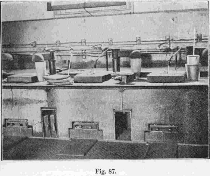
The pipe-stem is 24 inches long, tapering from 3/8 to ½ an inch at the end inserted into the gold, and is wedge-shaped to facilitate the escape of the chlorine when resting on the bottom of the pot. The bore of the pipe-stem is 1/8 of an inch in diameter. The thin end of the pipe-stem is attached to the branch delivery pipe by a piece of ½-inch rubber about 2 ½ inches long, which connects with an ebonite junction, G, 3 inches in length, with a bore of 1/10 of an inch, turned with a ring round the middle, which acts as a rest for the 8-oz. weight, H, used as a sinker for the pipe-stem. One end of the ebonite junction is ½ an inch in diameter, the other ¾ of an inch; the latter being connected by a stout rubber tube 3 or 4 inches long to a 14-inch lead pipe ( ½ an inch in diameter) which is attached [by a rubber junction] to a glass stopcock, I, from the spigot of which a ¾-lb. lead weight, J, is suspended to prevent the pressure of gas from blowing it out. The glass stopcocks have replaced the compressor clamps, which were not satisfactory owing to the rubber cutting through, and chlorine leaking past. The rubber joints are sufficiently flexible to allow the pipe-stem to bend down into the pot or to be laid horizontally on a rest when not in use. Each furnace is provided with one glass stopcock to control the flow of gas. The cock is far enough away at the back of the furnace, to be unaffected by the heat when the firetiles are removed, and is connected by a ½-inch lead pipe with the main pipe running along the wall. Thinner pipe-stems are found to be as serviceable as the above and do not require such careful annealing. The tubes, stopcock, &c., are somewhat diagrammatic in Fig. 86, and can be studied in Fig. 87, which is from a photograph of the furnaces. This also shows the crucibles, guard pots, ventilating hoods, and chloride cakes.
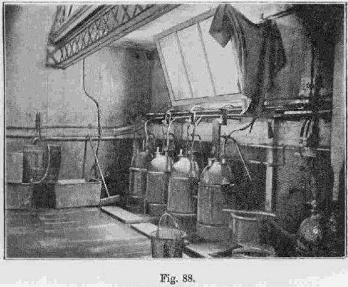
The generators are shown in Fig. 88. The pressure regulator and the reduction tank are also shown. The generators, eight in number, are three-necked cylindrical stoneware vessels with domed tops, and having a flange round the middle by which they are supported on the stoneware steam jacket 16 inches high, 16½ inches in diameter, and 5/8 of an inch thick. The domed vessel is 2 feet high. The three necks have 1¾, 1 3/8, and 1 3/8-inch holes, the first for charging-in the manganese ore and closed by an indiarubber plug, the second for the pipe leading to the main chlorine pipe, and the third for a branch acid supply tube, ½ an inch in diameter, fitted with a glass stopcock a foot above the neck, between which and the stopcock another ½-inch tube, the overflow, branches. The overflow tube, through which the hot waste of the generators has to pass, is provided with an ebonite stopcock which is turned off during refining. Stout combustion tubing is used. The bottom of the generator is covered by 4 inches of quartz pebbles, to prevent choking of the acid delivery pipe, which reaches to within 1 inch of the bottom of the vessel. 56 lbs. of manganese ore (about 73 per cent, peroxide), broken to ¼ to ½ inch square, is placed on the pebbles, and commercial hydrochloric acid, of specific gravity 1.16, is added as required through the acid delivery pipe by turning the glass stopcock. The acid pipe is of glass, and leads to the eight storage tanks, 20 feet above the floor, which hold 320 lbs. of acid each, and are interconnected by glass tubes luted into the bottoms; the delivery of acid, however, being from one at a time. The gas delivery pipes from the generators all connect with a 1-inch lead pipe, which leads to a distributing vessel with two necks, and partially filled with manganese chloride solution. A pressure gauge of 1 inch glass tube and 15 feet high is luted into the bottom of this vessel, and is fixed to the wall by brackets, 10 to 11 feet of the solution being required to overcome the resistance of about 7 inches of metal in the pots. The pressure in refining is equal to 5 lbs. per square inch. A four-way tube of lead or pottery is passed through the second neck of the vessel, and each arm is connected by thick rubber to glass stopcocks to which ½-inch lead pipes are joined, these pipes leading to sets of four, four and five furnaces, so that the supply of gas can be delivered to a few or all the furnaces, as desired, the subdivision being made for safety in case of a leakage or for convenience if only a few furnaces are in use. All the generators are used whether the quantity of gold to be refined be large or small, the same quantity of acid being run into each. “When the flow of chlorine through the gold is stopped the acid in the generators is forced back through the overflow pipe by opening the ebonite tap. It is found necessary to have the main pipe in communication with another two-necked earthenware vessel containing such a quantity of water that when the pressure of gas exceeds the working pressure required, the end of a glass tube, passing to the bottom of the vessel and connected above the neck with an upright 4-inch lead pipe 10 feet high, becomes unsealed, and the gas escapes through the water in large bubbles, escaping through a glass pipe, inclined at an angle at the top of the lead pipe, into the air. When sufficient gas has escaped to reduce the pressure to the working limit the pipe is sealed. Thus the pipe acts automatically in keeping the pressure below such an amount as would endanger the apparatus or cause joints to leak. It is found expedient to cover all the rubber junctions in the generating room with calico and then to paint it. Protected in this way it will last until stopped up by the action of the chlorine which fills it with a lemon-yellow incrustation, at the same time reducing its thickness. All junctions are secured with copper wire where practicable.
