The motion of the charge, that is the grinding media and the material undergoing grinding, within a mill is of considerable theoretical interest and practical importance, and for these reasons, has been the subject of considerable study by a number of workers, but, even so, no rigid and complete theory, covering all the aspects of the dynamics of the mill charge, has yet been produced. The practical importance of this subject clearly resides in the possibility of the prediction of the grinding behaviour, and other such characteristics, of a mill from the knowledge of the trajectories of the elements of the mill charge. The theoretical interest lies in the study of the dynamics of the system and in the derivation of equations to define the million of the elements of the mill charge in terms of fundamental quantities such as the size and the speed of rotation of the mill. A simple example of the practical importance of this information is in the use of the knowledge of the trajectories followed by the balls in a mill to determine the speed at which the mill must run in order that the descending balls shall fall on the toe of the charge, and not upon the mill liner. The impact of the balls upon the liner plates can lead to unduly rapid wear of the latter, and so to high maintenance costs.
In this chapter the motion of the particles constituting the charge of the mill will be considered; it being assumed that there is no slip between the mill shell and the charge. There exists another type of motion, in which the charge as a whole slips relative to the shell, which gives rise to the phenomenon of “surging”, but consideration of this type of motion will be deferred until a later chapter.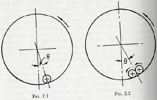
A study, from first principles, of the behaviour of a mill charge is much simplified if the charge is imagined to be composed of rods, instead of balls, since by this means the complication of any axial motion of the balls is eliminated and the problem is reduced to one in two dimensions. Consider first the motion of a single rod, of diameter d, within a smooth shell of internal diameter D; when the
shell rotates about a horizontal axis with an angulai velocity η radians per second. In such a case the rod will lie near the lowest point of the mill, as in Fig. 2.1 and will rotate at such speed that the peripheral speed of the rod is the same as that of the shell. Furthermore, the displacement of the radius vector joining the centre of the mill and that of the rod would be such that the work done by reason of the couple formed by this displacement is equal to the energy dissipated in the distortion of the rod and shell at the line of contact.
If now two rods are placed within the mill, as in Fig. 2.2, the motions of the surfaces of the rods at the point of contact are in opposite senses and free motion inside the shell is eliminated. In this case the angle between the vertical and the radius vector joining the centre of the mill and the centre of gravity of the pair of rods is much greater than that for a single rod. But, again, equality exists between the work done to rotate the shell and that dissipated in friction at the contact points and in distortion of the metal surfaces. A further increase in the number of rods would enhance this effect until relative rotation between the rods is largely precluded and, in this respect, the charge behaves almost as a solid body.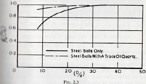
The correctness of this view is supported by the work of one of the present authors who, with a co-worker, Rose and Evans has shown that, for all other factors remaining equal, the power to drive a mill increases with the value of the ratio (D/d); that is for increasing numbers of small rods (in the experiments balls were used). This relationship, shown in Fig. 2.3 indicates, at once, that the displacement of the centre of gravity of the charge increases with an increasing number of balls, which is in accordance with the reasoning given above. This figure also shows that the variation in the displacement of the centre of gravity is much less when the coefficient of friction between the surfaces is high, which indicates that, for this condition, the locking of the charge is effective when but a few elements are involved.
If the speed of rotation of the mill is so low that the effects of centripetal acceleration may be neglected, then the displacement of the centre of gravity of the charge will increase until either of two possible limiting conditions is reached; these conditions being:
- The tangential force at the shell, necessary to maintain the displacement of the mass centre of the charge, becomes equal to the frictional force. When this state is reached the whole charge slips back.
- The angle of displacement, θ, reaches 30° when, since the centres of the rods in each layer then fall on vertical lines, the heap of rods collapses.
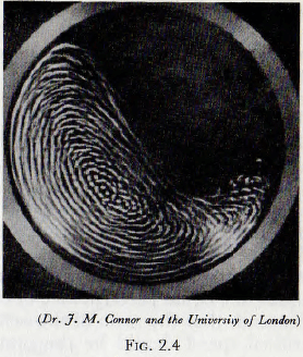
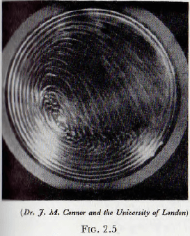
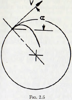
In fact this is a trivial case, since the effects of centripetal acceleration profoundly affect the motion of the elements of the charge, but for slow speeds of rotation the motion of the charge in a practical mill approximates to that given by case (2) above. In this motion the balls (or rods) will travel on circular arcs, concentric with the shell of the mill, until the point of instability is reached, after which they roll down the surface, which is inclined at about 30° to the horizontal, in a series of parallel layers. This motion is shown on a photograph taken through the transparent end of a model mill in Fig. 2.4. It will be noticed that a small “vortex” exists towards the middle of the charge. At higher speeds of rotation the balls no longer roll down the surface of the charge but, at a certain point, are projected into space and thereafter describe approximately parabolic paths before again meeting the ball mass; these ball paths being as shown in Fig. 2.5. There appear to be no universally adopted names for these two types of motion of the charge, but the evidence appears to be in favour of “cascading” for the first type and “cataracting” for the second type. These names will be adopted for the present work.
 |
 |
As the speed of rotation of the mill is increased the particles are projected with progressively greater velocities until the theoretical trajectory for a particle, which is in fact lying against the mill shell, would fall wholly outside the shell. Clearly, since the particle cannot pass through the shell, it would lie against the shell throughout the cycle and so be carried around continuously with the mill shell. This condition is known as centrifuging and the speed of rotation at which it occurs, for the outermost layer of particles, is known as the “critical speed” of the mill. This speed, the critical speed, is of considerable importance in mill technology since, for example, other factors being equal, the equal performance of two mills of different sizes demands that the ratio of the actual running speed to the critical speed should be the same for the two mills. An expression for the critical speed of a mill will now be derived.
By reference to Fig. 2.6, it is easily seen that if the trajectory is not to fall inside the shell, the radius of curvature of the path, e, must be greater than R, that is than that of the mill shell. Furthermore, this must be true for from wherever the trajectory might start.
From the dynamics of a particle it follows that for the trajectory,

Also, from elementary mathematics, the radius of curvature, e, of any curve is given by
e = {1 + (dy/dx)²}³⁄²/d²y/dx²
which by substitution (for example, see Todhunter’s Differential Calculus, p. 174) gives
e = (y’² + x’²)³⁄²/x’y” – y’x” ……………………………………(2.2)
Thus from the conditions specified e ≥ R, so, substituting from (2.1) into (2.2)
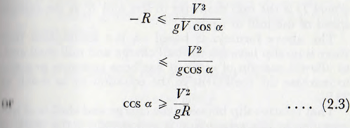
but cos α > 1.0 so the limiting conditions is α = 0 which corresponds to
V²/gR = 1
or, Since V = ωR, ω² = g/R
from which ω = √(g/R) …………………………………..(2.4)
When the diameter of the ball is taken into consideration, the radius of the outermost ball path is given by ½(D – d) which, when substituted for R in equation (2.4), gives
ω = √{2g/(D – d)}
and this on expansion by the binomial theorem leads to
ω = √(2g/D) · (1 + 0.5d/D) ………………………………(2.5)
If, as is usually the case in practice, the value of d/D is less than about 1/20, the second bracketed term may, in general, be taken as unity.
In this treatment ω is the angular velocity of procession of the mill charge and, because of slip between the mill shell and the charge, this is not necessarily equal to η, tin- angular velocity of the mill shell. If, as is often the case, this slip is assumed to be negligible, then ω = η and these equations may be cast into the slightly more convenient practical form

where D is the mill diameter in feet and Nc is the critical speed of the mill in r.p.m.
The above formula is based on the assumption that there is no slip between the ball charge and mill shell and, to allow a margin of error, it has been common practice to increase the coefficient in the equation by as much as 20%.
That relative slip between the charge and shell is of importance in this connection is supported by the work of Rose and Evans who report that, using ground steel balls in a small-scale model mill made of solid-drawn brass tube, centrifuging did not occur even at running speeds of 120 % of the critical value. However, when the same mill was fitted with effective lifters centrifuging occurred when the actual speed exceeded the theoretical value by a few per cent. This observation is confirmed by Grunder, who showed that centrifuging in a mill with porcelain balls and body occurred when the actual speed exceeded the calculated critical value by about 5% to 10%. It is questionable, however, whether with modern liners maintained in reasonable condition the increasing of the value of the inefficient of equation (2.6) by 20% is necessary or desirable.
Attention will now be turned to a more detailed analysis of the motion of the ball charge. In the first place, on the grounds of simplicity, the analysis first developed by Davis will be considered, even though, as shown later, it is, in certain respects, an over-simplification.
Consider a point P, Fig. 2.7, at which the projection of the particle occurs and let this point be at a distance r from the centre of the mill. In this connection, the “point of projection” may be considered to be the point at which the trajectory of the particle is influenced by gravity and is not wholly controlled by the packing of the surrounding charge.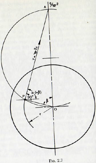
For projection to occur, it is necessary that the radius of curvature of the path under the influence of gravity should be smaller than the radius of curvature of the initial circular path. An expression for the radius of curvature of the path under gravity is given by equations (2.2) and (2.3) from which
r ≤ V²/(g cos α)
which for the limiting case and since V = ωr,
cos α = ω²r/g …………………………..(2.7)
From the geometry, however, it is clear that the line of projection PA must be at right angles to the radius vector OP so β = α and hence
r = (g/ω²) cos β ………………………(2.8)
This equation is satisfied when point Α is distance g/ω² above the centre of the mill, and furthermore, since the
angle OPA is a right angle and from the theorem of geometry that the angle within a circle is also a right angle, it follows that the line from which projection takes place is an arc of a circle of radius g/2ω²; the “Davis circle”.
By a simple substitution this leads to the expression
rc = 0.408/n² ………………………….(2.9)
where rc is the radius of the Davis circle and n is in r.p.m. Again, in this treatment, slip is usually neglected and so a represents the speed of the mill in r.p.m.
The trajectories of the ball paths may, on the assumption that the ball paths are parabolic, be easily plotted. Thus by the integration of equations (2.1) and taking the origin of the co-ordinate system at the point of projection.
![]()
and eliminating t between these equations
y = x tan α – gx²/2V²cos² α ………………………(2.11)
from which the parabolic trajectories may be plotted.
More important than a knowledge of the form of the trajectories is a knowledge of the form of the surface in which the parabolic trajectories terminate.
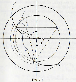
From Fig. 2.8, it is clear, from requirements of continuity, that the amount of material entering any annular element p ‘p q’q must be equal to the quantity leaving it and so, since the parabolic trajectories cannot cross, a trajectory must terminate in the same annular element as it originates. Thus, the surface bRc is defined by points, such as R, which are obtained by the intersection of the parabolic trajectory with a circle of radius r; where r is the radius at which the trajectory originates. A representative point, such as R, may be obtained by the determination of the values of x and y, taking the point of projection P as the origin, of the point of intersection of the parabola with the circle of radius r through P.
The equation of the circle referred to these co-ordinates is
x² + y² + 2rx sin α – 2ry sin α = 0 …………. (2.12)
and the equation of the parabola is given by (2.11). On substituting y from (2.11) in (2.12), the expression

is obtained; from which x² = 0 and also
(g²/4V² cos² α)x² – (g tan α)x – gr cos α + V² = 0
Now from equation (2.7),
V² = gr cos α
which substituted in the immediately preceding equation, leads to
x²/4r cos³ α – x tan α = 0
The solution of this equation are x = 0
and x = 4r sin α cos² α ……………………..(2.13)
It is clear that, in general, a parabola cuts a circle in four points and, in the present case, three roots of the quartic equation are zero whilst the fourth, given by equation (2.13), is that required.
When this value for x is substituted in the equation for the parabola, it is found that,
y = — 4r sin² α cos α …………………… (2.14)
Since, for most purposes it is not necessary to plot the whole trajectory, the representative point R may be obtained geometrically thus:
In Fig. 2.8 let point O be the centre of the mill and let the concentric circle RPQ represent the circular path of tin ball. The arc OPS is the arc, of radius g/2ω², representing the line at which projection occurs. Project a horizontal through P to cut the circle at Q and with centre Q describe an arc of radius QP, to cut the circle at R. The point R is then a point on the surface in which the “flying” balls meet the charge. Repeating the construction for a number of circles, of different radii, leads to the required surface bRC.
The proof of this construction is simple:
The length PQ = 2r sin α, and the length QR is given by
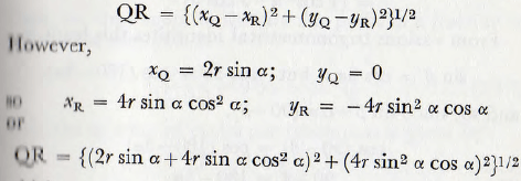
which on expansion and simplification leads to
QR = 2r sin α
Thus, PQ=QR and this is precisely the relationship used in the construction.
The curve ab is a circular arc struck from the centre of the mill and represents a surface which does not osculate with the segment of circle OPS, and, in consequence, from which no projection takes place. The radius of this arc is fixed by the magnitude of the mill charge and, denoting the radius by r, Davis gives the expressions

approximately; J being, in this expression, the fractional filling of the mill.
Since K cannot be less than zero, it follows that the mill filling cannot exceed about 0.7 without interference between the particles taking place. Actually Davis states that, in order that interference shall not occur, r should not be less than 0.228/n², where n is the speed in revolutions per second.
The fraction of the charge which is in “flight” can be calculated fairly simply thus.
The angle β in Fig. 2.8 is given, from equations (2.14), by
sin β = (1/r) (4r sin² α cos α – r cos α)
= (4 cos³ α – 3 cos α)
From various trigonometrical identities this leads to
sin β = cos 3α, but cos 3α = cos (180- 3α)
and so, since sin β=cos (90-β),
cos (90 – β) = cos (180 – 3α)
or 90 – β = 180 – 3α
or -β= 90 – 3α……………………………(2.17)
Now, the angle passed through by the particle whilst in the parabolic path is α + 90 + β which is α+ 90 + 3α – 90 or 4α.
If the speed of the mill is n r.p.m., the time per revolution T is 1/n and the time, T for the ball to cover the circular path is given by
Tc = T(360 – 4α/360)
Also the time required to traverse the parabolic path is given by
Tp = x/V cos α
= 2 sin α cos α/πη ………………………(2.18)
If now it is assumed that the motion of the charge may be represented by the motion of the particle at the radius of gyration of the charge, it is necessary to find the angle to corresponding to the radius
r = √R² + ri²/2
and this angle will be found to be 54° 44′.
By use of this angle and the above expressions, it is found that
![]()
Thus the time spent in the circular path, as a fraction of the time of the cycle is
0.39/1-0.3 = 0.56 = 56% …………………………….(2.19)
Also the number of cycles per revolution is given by
Tr/T = 1/0.7 = 1.45 …………………………………..(2.20)
Thus it follows that, as a first approximation, 56% of the time is spent in the circular path and also that the area between the mill shell and the curves dPabRC is 56% of the area occupied by the charge when the mill is at rest. It also follows that, on an average, every ball strikes another 1.45 times per revolution of the mill.
The analysis of Davis, just outlined, is open to criticism on a number of grounds. For example, the frictional characteristics of the charge are ignored, the effects of interactions between the elements of the charge in a given trajectory and the interference between adjacent trajectories are neglected, as are the centripetal forces acting on the particles. Furthermore, some of the equations involved appear to include a number of rather wide approximations. Even so this work was the first serious attempt to derive a rational theory of the ball mill and, whilst forming a good basis for mill calculations, it had also paved the way for later studies.
Theory of von Steiger
The first important modification to the above treatment was suggested by von Steiger; who pointed out that the hypothesis of free flight of the particle along the ascending branch of the parabolic trajectory is invalid since the continuous projection of material along any trajectory results in contact between the particles. Thus for the ascending branch of the parabola the speed along the arc is constant; not variable as is the case with free flight of particles.
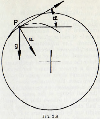
On referring to Fig. 2.9, it is seen that the intrinsic equation to the normal µ is, since the radial acceleration is provided by the normal component of the gravitational acceleration, given by
V²/e = g cos α
where e is the radius of curvature of the trajectory at the point P.
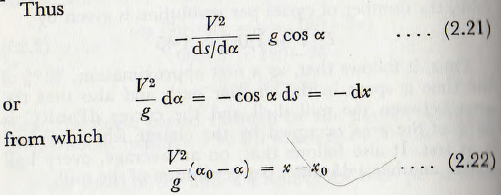
Also from equation (2.21),
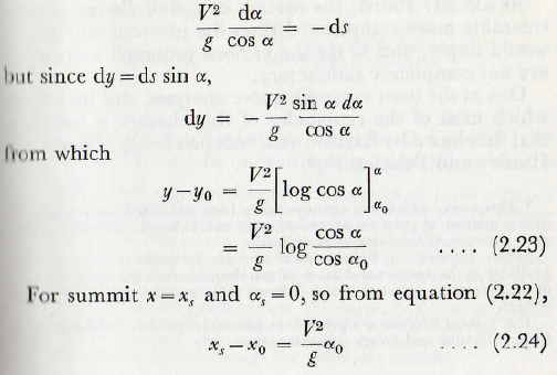
and from equation (2.23),
y – yo = V²/g log sec αo …………………..(2.25)
The surface from which the projection of the particles occurs is unaltered by this treatment and is, as before, given by a circle of radius g/2ω² drawn in the way previously explained. The trajectories themselves are considerably altered, however, since for the same initial conditions, the horizontal velocity of a particle, at the summit, is greater under the assumption of von Steiger, and so the particle travels a greater distance horizontally. Also the height of the summit above the point of projection is different in the two cases. Furthermore, since from continuity considerations, a trajectory on termination must cut the surface of the ball charge at the same radius as that at which it commences, it follows that the equilibrium surface of the ball charge is modified. These differences are clearly brought out by the diagram of Fig. 2.10 in which trajectories starting at the same point are plotted in accordance with the two treatments and the corresponding surfaces of the charge are shown.
As already stated, the motion of a mill charge is considerably more complicated than the previous treatments would imply, and so far the various proposed treatments are not completely satisfactory.
One of the most comprehensive analyses, and that upon which most of the remainder of this chapter is based, is that developed by Barth and, independently of Barth, by Hinsley and Fobelets.
In the first place the equilibrium surface of the mill charge is determined and for this purpose the effective coefficient of friction of the charge (balls plus powder) must be established. A generalized coefficient of friction may be determined by forming a large conical heap of
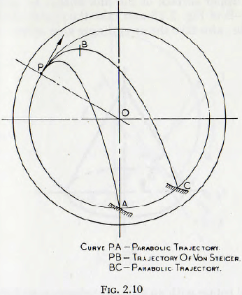
the mill charge on a flat surface, as shown in Fig. 2.11; the heap being formed by shovelling the material on to the apex of the cone and allowing the stable angle of repose to become established. The angle of repose, γ, is then measured and the coefficient of friction λ is given by
λ = tan γ ………………………….(2.26)
Let the upper surface of the mill charge be given by the curve A-B of Fig. 2.12 and take the centre of the mill as the origin; also take the co-ordinate axes as shown. Let the
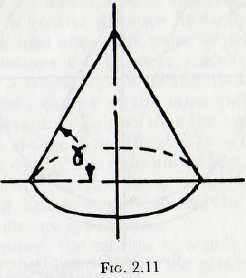
mill shell rotate with an angular velocity n and also assume that the particles of the charge describe circular aim around the origin with this velocity.
Now any particle, P, of mass m, on this surface, at a distance r from the origin, will be in equilibrium under the influence of three forces:
(1) The radial “centripetal” force: mrn²
(2) The weight: mg
(3) Frictional forces acting between the particle and its neighbours.
On equating the forces acting on the particle the following expression is obtained:
λmη² cos (β – α) + λmg sin β + mrη² sin (β – α) = mg cos β ……………(2.27)
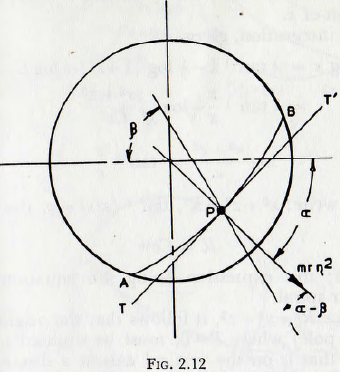
Multiply this equation by 1/mη² and rearrange.
λ(g/η² sin β + r cos β cos α + r sin β sin α) = g/η² cos β – r sin β cos α + r cos β sin α
and then substitute x = r cos α, y = r sin α, and also divide by sin β which then gives
λ(g/η² + x cot β + y) = g/η² cot β – x + y cot β
However cot β = dy/dx, so
dy/dx(g/η² + y – λx) = λ(g/η² + y) – x
Now let z = (g/η² + y), which, on substitution gives,
(z – λx) (dz/dx) = -λz – x
dz/dx = λz + x/λx – z
This is the standard form of homogeneous equation of first order and may be solved by putting z = kx, where k is a function of x.
This, on integration, gives,
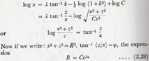
is obtained; this expression being the equation of an equiangular spiral.
Also, since R² = x² + z², it follows that the origin of the spiral (the pole) where R = 0, must be situated at x = 0, y= —g/η²; that is on the vertical axis at a distance g/η² above the centre of the mill. (It should be noted that this distance is also the diameter of the circle, the Davis circle, defining the surface at which projection occurs.) The coefficient C is a parameter which is related, but not simply, to the degree of filling of the mill.
The configurations of the surface of the charge with various values of speed, coefficient of friction and mill filling, as calculated on this basis, are shown in Fig. 2.13. Examination of this figure shows that, for a given mill filling and coefficient of friction, the surface configuration of the charge is not greatly altered by variations in (N/Nc) the ratio of the running speed to the critical speed. Similarly, for a given value of the ratio N/Nc and a given
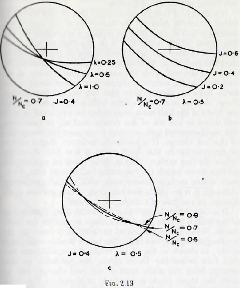
coefficient of friction, the slope of the surface does not alter greatly with the mill filling; furthermore, the line defining the surface is almost straight. In fact the average slope of the surface increases very slightly with decreasing filling.
The variable which has the greatest influence on the configuration of the surface of the charge is clearly the coefficient of friction and, all other variables remaining unaltered, the slope of the surface increases rapidly with increasing coefficient of friction.
Cascading Motion
It is desirable that the meaning of this surface should be borne clearly in mind. If the derivation of the equation is studied it will be seen that the equation represents the surface upon which a particle is in equilibrium under tin influence of the centripetal force, based on the assumption that the particle is traversing a circular path around the centre of the mill with the same angular velocity as the mill shell, of the weight of the particle and of the frictional force between the particle and the underlying surface. Now, clearly, in a real mill the balls which come up from the body of the ball mass must either be projected or must roll down to the toe of the charge and so, in cascading, this mathematical surface cannot represent the free surface of the ball charge. It is probable, however, that a surface of approximately this form exists a few ball diameter, below the free surface; that is, there exists an equilibrium surface down which the cascading ball charge rolls. Thus, such a free surface cannot exist with cascading motion, although it is probable that one does, over a portion of the charge, in the case of cataracting motion.
Theory of Davis
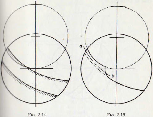
It is clear from the previous discussion that, if projection of the balls is to take place, the charge must cross the Davis circle. Now, the equilibrium surface, as defined by tin equiangular spiral, can fall either below or above the Davis circle; as shown in Fig. 2.14. When the equilibrium surface falls below the Davis circle, the particles, as they emerge from the main mass of the ball charge, pile up until the Davis circle is reached; as shown in Fig. 2.15. This is clearly possible since in the mass of balls lying above the main equilibrium surface but below the Davis circle, there exists an infinite number of equilibrium surfaces such as ab.
The inner bounding curve for this mass of balls is a circle concentric with the mill shell and tangent to the equilibrium surface. The position of this circular arc and the equilibrium surface is, of course, fixed by the condition that the “rolling” mass of balls and the “flying” mass are together equal to J, the static filling of the mill. Since, in this case, the projection takes place from the Davis circle, the construction for the termination of the trajectories, given earlier, is valid. In the second case, in which the equilibrium surface falls above the Davis circle, projection does not occur until the equilibrium surface is reached.
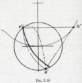
Since projection does not now occur at the Davis circle, the previous construction must be modified.
By reasoning very similar to that used previously, it can be shown that the termination of a parabolic trajectory, commencing at a point P’ above the Davis circle, is obtained when, on Fig. 2.16, distance P’Q’ = Q’R and the point Q’ is on the Davis circle. Thus, the construction is similar to the previous except that point Q’ is on the Davis circle whereas point Q is on the mill circle. So for either case the point of termination of the trajectories may be determined by simple graphical methods.
It is interesting to have a knowledge of the proportion of the charge which is in “flight”, and of that which is “rolling”; also to see how these quantities vary with the speed of rotation of the mill and with the coefficient of friction of the charge material. A simple construction for this purpose will now be described; this construction being due to Fobelets.
CASE 1. The point of projection on the Davis circle:
(a) As in Fig. 2.17, draw the mill shell circle and the Davis circle.
(b) With compasses determine position of point R ; the termination of the trajectory originating at P. (Use point Q on mill circle as centre.)
(c) From the pole C (on the Davis circle), draw radius vectors at 10° intervals; taking vector CR as datum.
(d) From C set out along the successive rays a length Ca = CR.e-λ(π/180)δ, where CR is the length CR
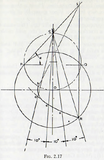
measured from the figure, δ is the angle, in degrees, from the line CR to the ray under consideration and λ is the coefficient of friction of the charge.
(e) Join the points such as “ a ” to give a smooth curve, from the centre of the mill, O, draw an arc of a circle tangential to this curve and to cut the Davis circle at b.
(f) Draw a line from P through C to intersect a vertical drawn through point R at point S.
(g) Repeat (b) and (f) using mill circles of various radii; and so establish the curve bS. (For most purposes this step may be dispensed with and points bS joined by a straight line. There is then some loss of accuracy but this is not generally of great practical importance.)
(h) Determine the area SbaRPCS. This when expressed as a fraction of the area of the mill circle gives J, the static mill filling.
(i) Determine the ratio of areas PCSbP and PbaRP; this ratio being the ratio of the “flying” charge to the “rolling” charge.
When the equiangular spiral enters the Davis circle the treatment is slightly more complicated and demands some trial and error. Thus,
CASE 2. The equiangular spiral enters the Davis circle:
(a) As for Case 1.
(b) Assume a position for the point of projection, P’, and using the construction of Fig. 2.16, determine point R; the termination of a parabolic trajectory which starts at P’.
(c) and (d) As for Case 1.
(e) Join points such as “a” and the equiangular spiral should pass reasonably close to P’. If it does not, start with a new point P’ and repeat the construction.
(f) to (i); As for Case 1.
The basis of this construction is as follows.
If the flight trajectories are parabolic, then the horizontal velocity x’ is constant and given by
x’ = ωr cos α …………………………(2.29)
where α is the angle of projection and the other symbol have the same meaning as before.
Also the time of flight, Tp, is given by
Tp = x/x’
= x/ωr cos α …………………………(2.30)
During this time, however, the rotation of the mill will bring, from the depth of the mass of the charge at radius r, a column of balls of length ωrTp.
This is the quantity of balls projected in time Tp, from a strip of width dr, and this may be written dqf. Then
dqf = ωr(x/ωr cos α)
= x/cos α …………………………(2.31)
From Fig. 2.17, however it is evident that
x/cos α = PS ………………………..(2.32)
Then, from equations (2.31) and (2.32)
qf = f PS dr
where the integration is carried out along the curve from b to P. This integral is, however, equal to the area of the figure bPCS and hence the construction.
Cataracting Motion
Although there is still an element of approximation in this treatment, it appears to be superior to that of Davis in that the effects of frictional characteristics of the charge are included and the computation of the “flying” charge does not involve reference to some mean radius. On the basis of this treatment it is possible to study the conditions for cataracting or cascading in some detail and this will now be done.
It will be noticed that, so far, no rigid definition of cascading and cataracting has been given. In fact such a definition is probably impossible since it now appears that there are not two types of motion of the charge involved, but a single type of motion in which, in certain cases, some details of the motion are not apparent. For the present purpose it is probably sufficient to name the motion “cataracting” when an appreciable gap exists between the parabolic trajectory of the innermost particle and the upper surface of the rolling charge. Cascading then corresponds to the motion in which this gap is so small as to give, in general, the appearance of being non-existent.
This difference is clearly shown in Fig. 2.18, which are the trajectories for a mill running with a definite charge at a definite speed but with different fillings. In Fig. 2.18a, with the higher filling, the space is very small and when allowance is made for the finite size of balls the mill would appear to be cascading. In the second illustration there is a definite space which, even allowing for interference between the balls in the different trajectories, would not be obliterated, and hence the mill would be described as cataracting. For the present purpose it will be assumed
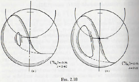
that when this gap is less than 0.05 of the diameter of the mill, the charge will appear to be cascading; this gap being chosen because, in view of the finite size of the ball in a real mill, it is improbable that a gap smaller than this figure would be discerned. By the plotting of a number of such figures the conditions for a gap of less than the specified size to occur are soon established. The construction for the determination of the “flying” and “rolling” ball charges is then applied to each of these limiting cases when the results given in Table 2.1 are obtained. Since any increase in the mill filling above these values will reduce the size of gap it follows that these values are the maximum static mill filling for which cataracting will be apparent.
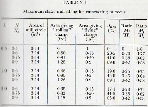
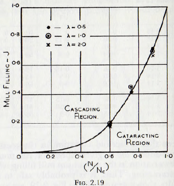
It is seen that a fourfold variation in the coefficient of friction produces, for a given speed of rotation, but a negligible variation in the maximum mill filling which will permit cataracting. Thus, it is probably safe to say that these results, shown graphically in Fig. 2.19, are applicable to any practical mill with an accuracy sufficient for any normal purpose. The general validity of these results has received an amount of indirect support in the following way.
The photographs of the motion of the ball charge, published by Rose and Evans, have been questioned on the grounds that they show no cataracting. A study of the original article shows, however, that the three cases are J = 0.25, J=0.5 and J=0.75, with N/Nc = 0.56 in each case. From Table 2.1, however, it is seen that each of these values of J is above the maximum for which cataracting will be apparent, and so the results shown in the photographs are to be expected.
The introduction of a coefficient of friction of constant value, as in the extended theory, is not completely adequate, however, since a study of Fig. 2.13b suggests that the average angle of slope of the surface of the charge should decrease with increasing filling, whereas the
measurements of Rose and Evans show that the slope increases with mill filling. This difference is easily explained since the charge consists of a limited number of balls of finite size and, in consequence, the energy dissipated in friction in the charge increases with the size of the charge. This has an effect equivalent to an increase in the coefficient of friction of the charge; and so brings about an increase in the slope of the surface of the charge, in the same way as is shown in Fig. 2.13a. Thus, it appears that the introduction of a variable value for the coefficient of friction λ, would bring about an even better agreement between theory and practice. Unfortunately, the introduction of such a variable quantity very much complicates the mathematical analysis.
A final, and very important, use to which the foregoing constructions can be placed is to ensure that the condition
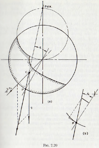
that the charge shall not slip on the mill lining is fulfilled. For this purpose,
(1) Use the previous constructions to determine the configuration of the “rolling” charge in the mill; shown shaded in Fig. 2.20a.
(2) Determine the position of the centre of gravity, G, of this area.
(3) Through G plot the radial acceleration ω²rG radially and the gravitational acceleration g vertically. (Note: radial force = MrGω² and vertical force =Mg, so these vectors are proportional to the forces.)
(4) Obtain the resultant of these vectors.
(5) Draw a straight line connecting the centre of mill O to the point P, where the resultant cuts the mill shell, and determine the angle ε.
(6) Compare tan ε with the coefficient of friction λ. For safety λ must exceed tan ε by a reasonable margin.
The last condition is clear from Fig. 2.20b, since the resultant has radial and tangential components as shown. The tangential component tends to give rise to slip at the surface and slip will, in fact, occur if the ratio of the tangential force to the radial force exceeds the coefficient of friction: that is if tan ε > λ.
