The apparatus listed in the following pages comprises the equipment necessary for complete and thorough testing of flotation processes. Some of it can be omitted where the problems to be studied are of a special character. It is urged, however, that such omission be of the actual flotation machines themselves rather than in the apparatus listed for preliminary tests. This is something that need not be demonstrated to the man who is experienced in flotation testing. Such a man knows that time spent in determining fully the mineralogical character of the ore to be dealt with will be time saved when the difficulties of actual flotation testing arise.
Preliminary Mineralogical Examination
Determination of mineralogical composition will require a part or all of the following equipment:
Books: “Introduction to the Study of Minerals,” Austin Flint Rogers, McGraw-Hill Book Co., Inc., New York; Hill Publishing Co., Ltd., London. “Minerals in Rock Sections,” Lea Mcllvaine Luquer, D. Van Nostrand Co., New York. “Elementary Chemical Microscopy,” Emile Monnon Chamot, John Wiley and Sons, Inc., New York; Chapman and Hall, Ltd., London. “Microscopical Determination of the Opaque Minerals,” Jos. Murdock, John Wiley and Sons, Inc. “Microscopic Examination of the Ore Minerals,” W. Myron Davy and C. Mason Farnham, McGraw-Hill Book Co., Inc. Apparatus and reagents for blowpipe analysis. A list is given by Rogers. Apparatus and reagents for qualitative microchemical analysis, including a simple polarizing microscope fitted with vertical illuminator for use in examinations by reflected light and with an eyepiece micrometer. Chamot describes such a microscope and lists such other supplies as are necessary. Apparatus and reagents for preparing rock sections and polished specimens for optical examination. Luquer, Murdock, and Davy and Farnham give complete lists. In connection with this latter apparatus, if but few rock sections are to be prepared and examined, the mechanical polishing apparatus can be dispensed with. Preliminary examination will be much facilitated by the use of a binocular microscope equipped with 25-mm. and 40-mm. objectives and 6X and 10X oculars. This microscope should have the usual stand with stage for work with transmitted light and also a small stand without stage which allows the microscope to be brought to and placed upon large objects, making possible a study of the same, without the necessity of preparing small specimens. Such a microscope as this is essential for investigation of the behavior of flotation froths and pulps in later stages of the testing work. An ordinary enameled gold pan and vanning plaque will be of aid also in the preliminary work and are necessary in later work.
Preparation of the ore for flotation
This will necessitate the use of the following equipment: Set of sizing screens. The Tyler standard screen scale sieves, ranging in size of aperture from 2.362 mm. to 0.074 mm., are suggested. Pair of platform scales with 500 lbs. capacity for weighing in lots of ore. Small sample jaw crusher. Braun disk pulverizer. Laboratory ball mill about 18 ins. by 18 ins. Set of balances of the druggist trip scale variety, 10-lb. or 5-kilogram capacity, with beam graduated to 500 grams by 10-gram intervals and to 16-oz. by 1/4-oz. intervals. Six-inch by six- inch Jones riffle complete with four pans and scoop. One-pound paper sacks for sacking samples preliminary to testing. Supply of 1-qt. and 2-qt. Mason jars for wet pulp samples.
Flotation Testing Machines
The machines described below are more than will be needed in an ordinary flotation testing laboratory, but the descriptions are included here for the sake of completeness. The particular field of each machine is stated in connection with the detailed description.
Gabbett mixer
This piece of apparatus is illustrated in U. S. patent 835,120 as having been used in the treatment of ores by agitation to produce a froth concentrate, and is the best laboratory apparatus in which to make a froth concentrate of the nature described in that patent. If a study is to be made of the development of froth flotation processes, this machine should be in the laboratory. The laboratory machine is shown in Fig. 1. It consists of a glass cylinder (a) open at both ends, mounted vertically in a hemispherical bronze casting (b). This casting is fitted with outlets (c) and (d) and is mounted on legs (e). These are fastened to a plank which forms the base of the stand carrying the agitating mechanism. The agitating mechanism consists of a stirrer (g) which has the shape of the frustum of a cone and is usually placed as shown with the large end down. This conical shell is fastened to the vertical spindle (h) by means of arms (i) and (j). The vertical spindle is supported by the post bearing (k) with two boxes (l) and (m) respectively and the thrust bearing (n) at such a height that the lower edge of the conical agitator clears the bottom of the chamber by but 1/4 to 1/2 in. The shaft is driven by means of a grooved pulley (o), 2-in. diameter, and a 3/8-in. round leather belt from the motor. Removable baffles (s) are provided for use when a high degree of agitation is desired. The post bearing (k) is carried on the vertical member (p) fastened by an angle to the base and braced. An annular overflow launder (r) is fitted to the cylinder (a). A 1/4-h.p. variable speed horizontal motor should be used to drive the machine and should be set up with its pulley not over 1 ft. from the center of the driven pulley, if belt trouble is to be avoided. The motor speed and pulley size should be such that the speed range of the mixer spindle will be from 200 to 2000 r.p.m. A machine of the size shown takes a charge of 300 to 350 gms. of ore according to the percentage of solids desired in the pulp.
The Slide Machine
The Slide was invented to overcome the difficulty encountered in removing froth from the Gabbett machine. It is shown in Fig. 2 and consists of a square box (a) supported on four legs as shown. The top of the box carries a trough (b) with the bottom flush with the upper edge of the box and with sides about 1/4 in. high. Above the box (a) is placed the sliding square pipe (d) of the same cross-section as the box and flanged to fit loosely, in the trough (b) and to slide therein. A rubber gasket is provided which fits the surface of the trough and permits of a tight joint between the upper and lower sections of the machine when the two are clamped together by means of screw clamps. Both box (a) and slide (d) are provided with plate glass windows (g) and (h). Agitation is effected by means of a four-armed stirrer carried on the vertical spindle (j) which passes through a stuffing box in the bottom of the box (a) and is carried on the step bearing (k). This shaft is actuated by a grooved pulley (l) and round leather belt from a 1/4-h.p. horizontal motor. This motor should give a speed range of from 800 to 2400 r.p.m. and should be set up with not more than a foot between pulley centers. The charge for this machine is 300 gms. of ore.
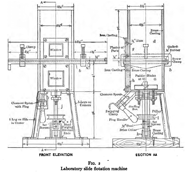
For ordinary testing of the agitation-froth flotation process this machine has been superseded and it now has no place in any but the most complete flotation laboratory.
Minerals Separation Standard machine
A laboratory model of this machine is manufactured and sold by the Denver Fire Clay Co., under the name of the Case laboratory flotation machine. It can, however, be made up in the laboratory for much less money than it can be purchased, and the home-made machine will give just as satisfactory results. Such a machine is shown in Fig. 3. It consists of a square box (a) made of 7/8-in. plank, or, better, metal, mounted on a plank (b). At one side of the agitating compartment (a) is joined a froth-separating compartment (c). Pulp passes from the agitating compartment into the froth-separating compartment through the slot (d) over which is placed the baffle (e), the purpose of which is to lessen the disturbance of the surface of the pulp in the froth- separating compartment. Circulation of pulp is accomplished through the pipe (f) which consists of a rubber hose slipping over nipples (g) in the back of the froth- separating compartment at the bottom and in the center of the bottom of the agitating compartment. Agitation is effected by means of a four-armed stirrer (h) attached to the bottom of a vertical spindle (i) which latter is supported by the bearings (j) and the thrust bearing (k) and is actuated through the grooved pulley (l) and a quarter-turn round belt from a 1/4-h.p. motor, placed best not more than 1 ft. distant. The froth-separating compartment (c) is fitted with an overflow lip (m). Tailing is withdrawn from the machine by removing the plug (n). The motor should be variable speed so connected as to allow a speed range for the vertical spindle of from 800 to 2000 r.p.m. The machine shown takes a charge of 750 gms. of ore.
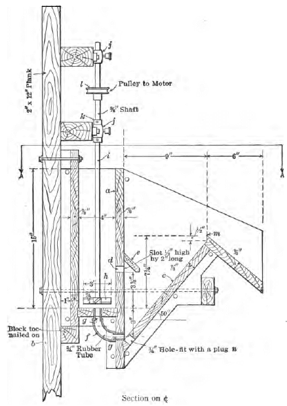
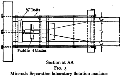
This type of machine is not the most satisfactory for laboratory testing for the reasons that the froth-separating compartment is too large, the pulp circulation is poor, and it is difficult to clean up. It can be improved by narrowing the froth- separating compartment. For routine tests of the agitation-froth process the Janney laboratory machine is far superior.
The Janney
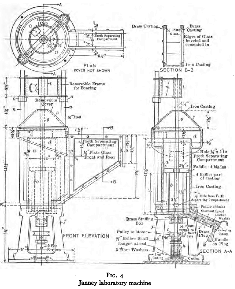
The Janney flotation test machine shown in Fig. 4 consists of a cylindrical agitation compartment (a), fitted on the periphery with radial baffles (b). Attached to one side of the agitating compartment is a froth-separating compartment (c). The front of this froth-separating compartment is cut down to a beveled edge to allow overflow of froth. Around the agitating compartment at the top is placed the annular launder (d). The machine is covered with a removable hemispherical cover (e) with a hole at the top. The base of the casting forming the agitating compartment is flanged and sits upon a frame (f). Agitation is effected by means of two four-armed impellers placed one near the bottom and one near the top of the agitating compartment. These impellers are carried on the vertical spindle (g) which passes through a stuffing box in the bottom of the agitating compartment. The lower end of this spindle is carried in a step bearing (h). The vertical shaft is actuated by means of a quarter-turn round leather belt and a grooved pulley (i) from a 1/4-h.p. variable speed motor set preferably with pulley not more than 1 ft. away. The agitating compartment is fitted with a spout (j) and brass plug with handle (k) for draining residues from the machine. The motor should be such as to give a speed range of from 500 to 2400 r.p.m. A useful addition to the above machine consists in an upper removable bearing for the agitator shaft. This is shown in the figure and consists of a bearing (l) carried on the horizontal pieces (m) which are fitted to slide freely on the uprights (n) and are stopped by the collars (o). The vertical spindle is now extended to pass through the bearing (l), thus doing away with whipping of the shaft during agitation and lessening materially the wear on the stuffing box and step bearing. This shaft extension also makes possible the determination of the speed of the impeller shaft, which is impossible in the machine as sold. The ore charge to produce a pulp of 20 to 25 per cent, solids is 500 to 600 gms. The Janney machine is the best apparatus for routine testing by the agitation- froth process. It may be purchased from the Stimpson Equipment Co., Salt Lake City, Utah.
The Elmore vacuum laboratory machine
A convenient form of laboratory apparatus for operating the Elmore vacuum process is shown in Fig. 5. In the assembly sketch, (B) is the feed funnel discharging through the valve or stop cock (A) and the tube (H) through the bottom of the plate (I) into the vacuum chamber. Suction is applied to the pulp in the vacuum chamber through the dome (J), pipe (E), and concentrate receiver (F), by means of a pipe connecting the latter with the vacuum pump. Operation of the apparatus is intermittent. After a full charge is fed in, the valve (A) is closed, suction is applied and the rake slowly revolved. The froth which rises to the surface passes up through the inverted funnel into the dome (J) and out through the pipe (E) into the bottom of the concentrate collecting chamber (F). After all froth has been taken off, the vacuum is relieved and tailing withdrawn through the pipe shown at the left hand side of section (AA) passing through the bottom of the plate (I). It will be noted that the detail drawings show provision for belt drive for the rake rather than for the bevel gear drive illustrated in the assembly. The belt drive is simpler and cheaper. The funnel shaped cover for the vacuum chamber and the dome (J) are made of glass about 8/32 inch to 1/8 inch thick. The concentrate receiver (F) can well be made a wide-mouthed bottle. It is planned to operate the rake at 10 to 12 r.p.m. The machine takes a charge of 300 to 500 gms. of ore.
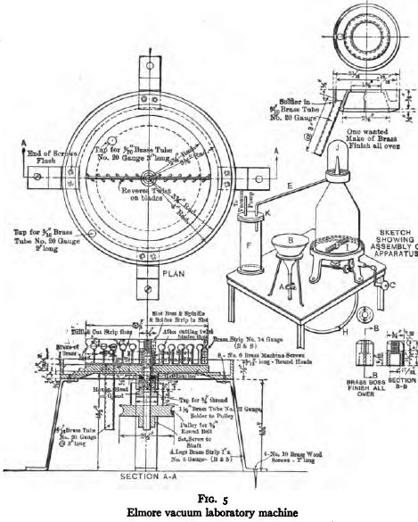
This machine is extremely satisfactory for laboratory testing of ores by the vacuum process. Good recoveries and high grade concentrate can be made and the phenomena are clearly visible.
The K and K laboratory flotation machine
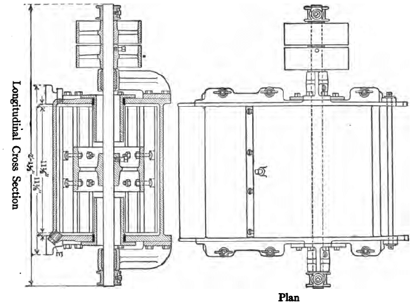
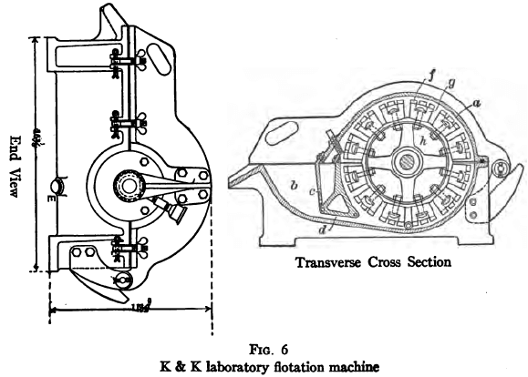
The float machines shown in Fig. 6 is manufactured by the Braun Corporation, Los Angeles, Cal. It consists of a horizontal split cylinder (a), the lower half being carried on legs while the upper half is hinged at the back and carries the bearings for the rotor shaft. Cast in one piece with the lower half of the cylinder just described is a froth-separating box (b) the length being the same as that of the cylinder. This box connects with the aerating chamber by ports (c) through which aerated pulp enters and port (d) by means of which pulp passes back for more aeration. It is also fitted with a drain cock (e) for drawing off the residual pulp after treatment. The aerating mechanism consists of a slatted cylinder made up by fastening slats (J) to the large slats (g) which are in turn bolted to spiders (h) carried on the shaft. The shaft is driven by pulley as shown. The machine will require a 1/4-h.p. variable speed motor fitted with a crown pulley to take a 2-in. belt. Motor pulley and speed should be such that with a 6-in. pulley on the machine, a speed range of from 200 to 800 r.p.m. can be attained. This machine requires a charge of about 750 gms. of ore for a test with a pulp containing 20 to 25 per cent, solids. The machine is useful for studying the behavior of an ore subjected to bubble-column concentration with an amount of air considerably less than that introduced in pneumatic machines.
The Ruth flotation testing machine
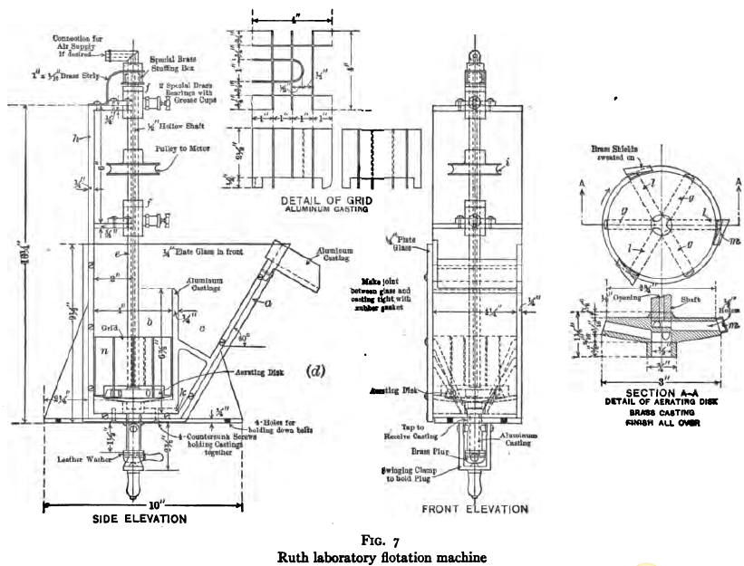
It consists of a box (a) partially divided, as shown in Fig. 7, into an aerating compartment (b) and a froth-separating compartment (c). The froth-separating compartment is connected at the bottom with the aerating compartment by means of a passage (k) which connects the bottom of this compartment with the bottom of the aerating compartment, entering directly under the vertical spindle. Aeration is accomplished by means of the hollow disk (d) which is carried on the lower end of the hollow vertical shaft (e). This latter is supported by post bearings (f) and thrust bearings on the frame (h). The shaft is actuated by means of a 3/8-in. round leather belt passing over the grooved pulley (i). Another form has two vertical grooved guide pulleys on the frame allowing the motor to be mounted on the same base as the machine. The hollow disk on the lower end of the vertical spindle is shown in plan and section in the figure. Ports (g) circulate pulp by centrifugal force. Air enters through the hollow shaft and ports (l) to fill the vacua formed behind the shields (m) as the disk rotates. A grid (n) prevents disturbance of the surface of the pulp and aeration of the pulp from the surface. A 1/4-h.p. variable speed motor giving a speed range of from 500 to 2000 r.p.m. should be provided. The solid charge required for a machine of this size with a pulp of 20 to 25 per cent, solids is 500 gms. This machine is sold by the Mine and Smelter Supply Co. of Denver, Col. The Denver Engineering Works Company is the manufacturer and sales agent for the mill-sized machine. The Ruth machine is of the bubble-column type but introduces less air per unit volume of pulp than the pneumatic type machines. The testing machine is efficient for this kind of operation.
The Hebbard
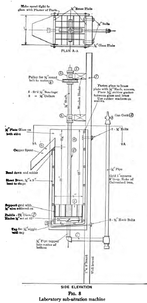
This sub-aeration laboratory machine (Fig. 8) consists of a square box (a) with slightly sloping bottom and with the front side cut down to allow discharge of froth over the lip (b). To the bottom of the box is attached a pipe (c) which is carried up outside the machine to a point about 3 ins. above the top and is there terminated by a gas cock (d). A grid (e) is placed with its lower edge about 1 in. above the bottom to prevent the formation of a vortex at the surface. Aeration is accomplished by means of the four-armed cross-shaped beater (f) fitted with arms at 45° from the horizontal and mounted on the lower end of the vertical spindle (g). This spindle is carried on the bearings (h) and the thrust bearing (i) from the framework (j) and is driven by means of a 3/8-in. round quarter-turn belt and the grooved pulley (k) from a 1/4-h.p. variable speed motor, set up at a distance preferably not more than 1 ft. The speed range should be such as to allow variation of from 500 to 2000 r.p.m. of the vertical spindle. This machine requires a charge of 750 gms. of ore for a pulp containing 20 to 25 per cent, solids. The machine introduces much more air than is introduced by the agitation-froth type machine and the concentration obtained is of the bubble-column type. It is a satisfactory piece of laboratory apparatus.
The Callow pneumatic laboratory flotation machine
This apparatus furnished by the General Engineering Company, Salt Lake City, is illustrated in Fig. 9. It consists essentially of a rougher cell 2 ins. wide by 15 ins. long and a cleaner cell 2 ins. wide and 7 ins. long, with an air lift for returning products to the head of the rougher cell. The rougher flotation cell itself consists essentially of a rectangular box (a), with a porous bottom made of several plies of light weight canvas or palma twill stitched together and clamped between the top of a four-compartmented chamber or air box (b) and the flanged bottom of the box (a) by means of screw clamps (c). Each compartment of the air basket is connected through the valves (B) with a header, in order, by adjustment, to permit equal distribution of air against the varying head at different points in the length of the cell. The depth of the cell at the head end is about 6 ins. and at the tail end about 11 ins. The cell is provided with an overflow launder (d) on both sides. These launders join at the tail end in a spout which delivers rougher froth to the cleaner cell. The rougher cell is drained by a pipe with a two-way cock (F) which discharges through pipes (G) and (H). Outlet (G) discharges into the air lift. It permits regulation of the pulp level in the rougher cell and allows circulation of rougher tailing during a test, if desired. Outlet (H) is for draining and washing out the rougher cell at the end of a test. The cleaner cell has a two-compartmented air basket and is fitted with an overflow launder similar to that on the rougher cell. Pulp level in the cleaner cell is regulated by the inclination of the pipe (E). The overflow from this pipe goes to the air lift and back into the system. This apparatus requires a charge of 1500 gms. of ore for a test. Eleven cubic feet of air per minute at 5 lbs. pressure should be furnished.
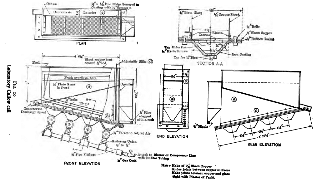
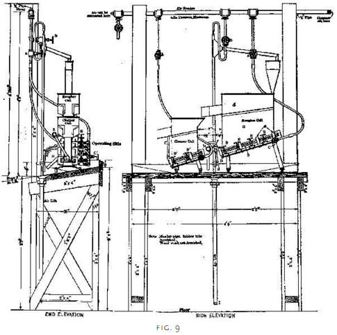 Figure 10 shows a much less elaborate apparatus, which the writer has found to be entirely satisfactory for laboratory testing of pulps by the pneumatic process. It consists of the usual rectangular box (a) with sloping porous bottom (b) fitted, however, with overflow launder (c) on one side only, the other side being of glass to permit observation of the interior. The construction is sufficiently shown in the sketch. The machine can be operated continuously by arranging feed rate and the tailing-discharge slide (d) to permit sufficient treatment time, or the tailing discharge pulp can be circulated by means of an air lift. If intermittent non-circulating treatment is desired the tailing gate can be stopped up by suitable means. The charge of ore for a pulp containing 20 to 25 per cent, solids is 1500 gms.
The General Engineering Co. recommends a positive rotary blower of the Root or Connersville type and says that the oil in the air from a compressor chokes the blanket. The writer has found, however, that a small compressor such as the Ingersoll-Rand Imperial Type 14, air-cooled, 2 1/2 ins. by 3 ins., using an ordinary house hot-water tank as a receiver, makes a more satisfactory installation than a blower. Pressure in the receiver should be maintained at about 10 lbs. Pressure on the blanket side of the regulating valves will vary from 1 to 3 lbs.
A pneumatic machine of one of the types above described should be in every general flotation laboratory.
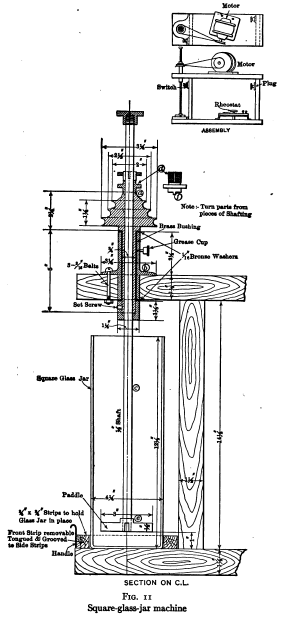
For preliminary qualitative tests of the agitation-froth process and for all kinds of stirring and mixing operations, a small bar mixer or the rather more elaborate device known as a square-glass-jar machine shown in Fig. 11 is extremely useful. The latter device consists essentially of a stirring mechanism and a removable square- glass-jar, mounted on a frame with a motor and rheostat and stop switch. The stir- ring mechanism consists of a vertical shaft (c) carrying at the lower end a four- armed paddle (e). A grooved cone pulley (a) with hub extended to run in the brass- bushed bearing (b) carries on its upper face a slot which is engaged by the lug (f) on the lower face of the compression collar (d). This arrangement permits the distance to which the stirrer projects into the jar to be easily varied at will and allows the stirrer to be lifted above the top of the jar when the latter is to be removed or set in place. A variable speed 1/4-h.p. motor, giving a speed range on the agitator shaft up to 2500 r.p.m. should be supplied. An ore charge of 300 to 350 gms. can be treated in this machine.
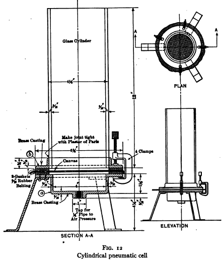
For preliminary qualitative tests by the pneumatic process, the apparatus shown in Fig. 12 is useful. It consists of a three-legged brass casting (a) and a brass flange (b) which takes a 4-in. gage glass. The flange is fastened to the gage glass by means of plaster-of-Paris. A piece of canvas or twill to serve as a porous bottom is clamped between the parts (a) and (b) by means of screw clamps. An overflow may be simply provided by cutting a hole of the proper dimensions in the bottom of a shallow pudding tin 6 ins. internal diameter and fitting the same with a discharge spout. Air is provided as for the laboratory Callow cells. The ore charge for this machine is 200 to 300 gms.
Cascade laboratory flotation machine
This apparatus is not standardized. A satisfactory apparatus consists of a cylindrical bottle of about two liters capacity with a gradual slope from full cross-section to neck, with the bottom cut off and the cut edge ground to a plane. This is set up in an inverted position, with a one-hole rubber stopper and glass tubes of various bores for regulating the discharge, about 12 to 18 ins. below a pulp reservoir or pressure box from which pulp discharges through a tube just large enough to allow free discharge. Settling of sand in the reservoir should be prevented by slow stirring. The stream of pulp from the reservoir spigot plunging into the body of pulp in the inverted bottle carries in air which causes concentration by bubble-column action. If the inverted bottle is fitted with an overflow launder such as is described in the preceding paragraph, and if the tailing is caught in a bucket and returned manually to the reservoir at such a rate as to make the discharge continuous, a fair quantitative result can be obtained.
Motors and Current
Motors. The five motors specified below are recommended by the Stimpson Equipment Co. for use with Janney laboratory machines, and are, of course, suitable also for use with the other types of machine where 1/4-h.p. motors are specified. The writer has used two of these types of motors and has been assured by users of the other types of their entire satisfaction with them.
Alternating Current
General Electric Co. Type SCS–521-4; 1/4-h.p.; 1800 r.p.m. Variable speed, reversible running. Single phase. 60 cycles. Form G–BR. Amperes 4.2 to 2.1. Volts 110: 220. Speed, full load, 1800 to 900 r.p.m. A dial controller brake to vary the speed is supplied at an extra charge.
Kimble Electric Co., 634–646 N. Western Ave., Chicago. Single, two or three phase circuit. Variable speed, reversible running, 110 or 220 volts. Speed 500 to 2000 r.p.m. A contained lever starts or stops motor; reverses or changes the speed.
Direct Current
General Electric Co. Type SD. Constant speed. Shunt wound. Volts 110. Speed 1700 r.p.m. Field rheostat for armature circuit. Ohms 50. Amperes 3 to 1 1/2.
Type DSD. 1043A. Constant speed. Shunt wound. Max. volts 250. Speed 1700 r.p.m. Field rheostat for armature circuit. D.L–T. Type F. Cr. 8000. Ohms 240. Am- peres 1.25 to 0.63.
Westinghouse Electric and Mfg. Co. Type CD. Shunt wound. Continuous duty. Volts 230. Amperes 1.2. Speed 1725 r.p.m. A field rheostat must be used in connection with motor.
The Robbins and Myers Co., Springfield, Ohio. List D142. Volts 110. Speed 1750 r.p.m. A field rheostat must be used in connection with motor. In all cases specify 3-in. grooved pulley for 3/8-in. round belt.
Flotation table
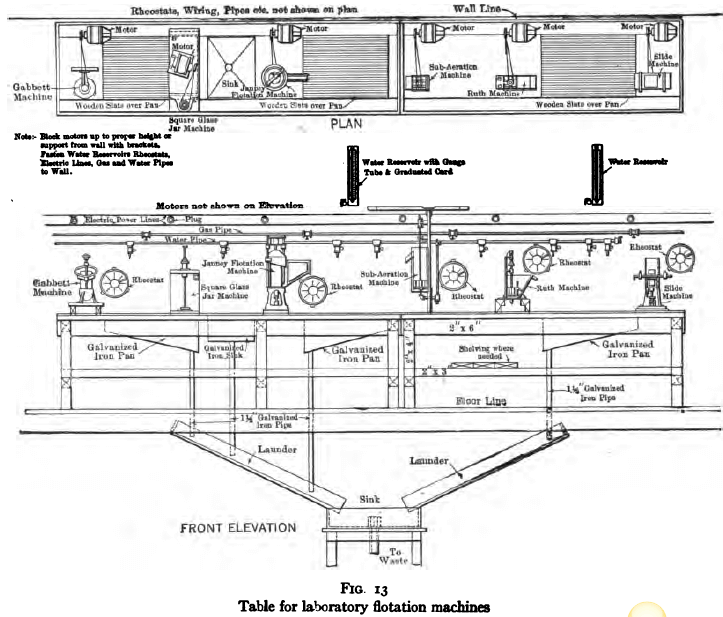
A convenient method of mounting flotation test machines is shown in Fig. 13. It consists of a solidly built table, with 2-in. cypress top except where grids and sink are shown. The grids are made of 1/2in. by 3/4-in. cypress, spaced 1/4 in. in the clear. Grids and solid top are so disposed as to allow space for a machine on both sides of each grid. About 2-ft. length of solid top should be allowed for each machine. The table is best placed against a wall along which are carried power, gas and water lines with numerous convenient outlets. Where several machines are not in use at one time the number of motors may be reduced by placing a stand at each machine of proper height for the motor and placing a rheostat and stop switch on a board which bolts with wing nuts to the wall and which carries an electric plug to connect with the nearest convenient power outlet. With a device such as this a motor with its rheostat can be readily moved within 5 or 10 minutes. The water reservoirs are small galvanized tanks 3 ins. square of about 3000 cc. capacity and are fitted with gage glasses and a calibrated card reading to 100 cc. A piece of rubber tubing is attached to the faucet and provided with a pinch cock at the lower end. This makes it easy to regulate and measure the amount of water used during the test.
Flotation Agents
Principal flotation agents or “oils.”
The following is a list of the principal oils used in ordinary practice. Steam-distilled pine oil, turpentine, pine-tar oil, coal tar, coal-tar oil, coal-tar creosote, wood tar, wood-tar oil, wood creosote, petroleum residuum, crude kerosene, sludge-acid kerosene, alpha naph-thylamine, xylidin, crude cresol, crude carbolic acid. Dealers are glad to supply samples of oils and the laboratory stock soon becomes large. In general it is unwise to do any extended testing work with a sample of which an insufficient amount is on hand for physical tests, because without such tests it is impossible to specify the oil accurately, if it should be desired, as a result of the tests, to buy. Proper physical tests require a minimnm of 1/2 gallon of oil. The following is a partial list of firms which manufacture and distribute flotation oils: American Creosoting Co., Chalmette, La., (1); American Tar Products Co., 208 So. LaSalle St., Chicago, Ill., (1); Associated Oil Co., Los Angeles, Cal., (4); Barrett Co., 17 Battery Pl., New York, and in principal cities, (1); Cleveland Cliffs Iron Co., Cleveland, Ohio, (2); Denver Gas and Electric Co., Denver, Col., and gas companies in other principal cities, (1); Georgia Pine Turpentine Co., 156 Perry St., New York, (2); General Naval Stores Co., 175 Front St., New York, (1), (2), (3); Geo. P. Jones and Co., 205 No. Lever St., St. Louis, Mo., (4); F. J. Lewis Mfg. Co., 2500 So. Robey St., Chicago, Ill., (1); National Aniline and Chemical Co., New York, branches in principal cities, (1); Pensacola Tar and Turpentine Co., Gull Point, Fla., (2); Semet-Solvay Co., Chalmette, La., (1); Standard Oil Co., branches in principal cities, (4); Texas Oil Co., Port Arthur, Tex., (4); Union Oil Co., Mills Bldg., San Francisco, Cal., (4); Utah Oil Refining Co., Newhouse Bldg., Salt Lake City, Utah, (4); Yaryan Naval Stores Co., Brunswick, Ga., (3). (The figures (1), (2), (3), and (4) indicate coal-tar products, destructively-distilled wood products, steam-distilled pine oil, and petroleum products respectively.)
Minor agents
Sulphuric acid, lime, sodium carbonate, copper sulphate, sodium sulphate, sodium hydroxide, sodium silicate, sodium sulphide, calcium sulphide. The first four are most used
Oil Testing
For testing oils the following apparatus is necessary. Specific gravity bottles 5 cc., 10 cc., 25 cc. and 50 cc. Engler viscosi-meter for viscous oils and Ostwald viscosimeter (Figs. 20, 21) for mobile oils. Refractometer. Hydrometers with range from 0.7 to 1.3. Oil distillation apparatus (Fig. 23) consisting of 1000-cc. and 250- cc. distillation flasks with side tube at the middle of the neck, 360-degree thermometer accurately calibrated; copper trough condenser. One 120-cc. separatory funnel with stem graduated to 20 cc. by 1/10-cc. Hand centrifuge with four Babcock cream-testing bottles, with neck graduated for 2 cc. by 1/25-cc. Special tar- acid separatory funnel 100-cc. capacity, as shown in Fig. 22. Ostwald gas regulator for constant-temperature baths.
Miscellaneous Apparatus
The following items need no further description. Pulp balances, 200 gms. capacity. Pipettes (Mohr’s), Fig. 14, two each, 1-cc. by 1/100-cc., 2-cc. by 1/50-cc., 5-cc. by 1/10-cc., and 10-cc. by 1/10-cc. Graduated cylinders capacity 5-cc., 10-cc., 25-cc, 100-cc., 500-cc., 1000-cc. and 2000-cc. Sugar thermometer with enclosed paper scale reading from o°, to 50° C. Speed indicator. Two doz. granite pans 8 in. by 15 in. by 2 in. Assorted beakers. Means for heating pulps and drying samples.
An assay laboratory in connection with the testing laboratory is essential for any extensive work.

Taggart P. 44-77
