The cost of replacement of the metal worn from the working surfaces of the balls and liners of a mill often represents a considerable fraction of the cost of operation of the plant and so is of some real economical importance. In spite of this importance, however, the amount of information in available on this subject is amazingly small and, unfortunately, is insufficient to form the basis of more than a very tentative analysis of the problem. As far as is known the only attempt to derive a theory for metal wear is that of one of the present authors, Rose, and the relevant parts of this treatment will be outlined briefly here.
The basic idea underlying this treatment is that particles of the material undergoing milling will, upon contact, be driven into the surface of the balls at a rate which depends upon the relative hardnesses of the ball and particle, the quantity of powder present and upon other such factors. It is also assumed that, provided there is relative tangential million between a pair of balls, one or other of the embedded particles will, upon making contact, as in Fig. II. 1a, be torn out. This then leads to the conclusion that the particles will be torn from the metal surfaces at a rate which is a function of the relative hardness of the ball and particle, of the number of particles embedded, the relative sliding velocity, and similar factors.
When the rates of embedding and removal of particles in equal there will be an equilibrium number of particles embedded in the metal surfaces or, in other words, a certain portion of the surface of each ball will be “armoured” with embedded particles. If now, an embedded particle in one ball traverses the “unarmoured” part of the surface of a neighbouring one, as in Fig. 8.1b, then metal wear will take place. In the work cited the calculation of such wear has, to a first approximation, been carried out and it is suggested that the relationship between rate of wear and relative hardness of ball and particle has the form shown in Fig. 8.2, whilst the relationship between rate of wear and quantity of powder in the mill has the form of Fig. 8.3.
 |
 |
Although the derivation of these curves is completely theoretical there is some qualitative evidence in support of their validity. Thus for example, it is clear from Fig. 8.2 that if a material is being ground by balls of approximately equal hardness (H= 1), then the ball wear may be reduced either by increasing or by decreasing the value of H. If however, a hard mineral, say of Brinell Number about 500 to 600, is being milled, it is not practicable to use balls of appreciably greater hardness and so the reduction of wear by increasing the hardness of the grinding surface is not possible. In such a case, however, the rate of wear can be reduced by the use of very soft metal (by reducing H) and so carrying the operating point well to the left of the maximum of curve Fig. 8.2. This improvement is, of course brought about by the increased “armouring” of the surface of the balls by the particles. Conversely when a very soft material is being ground, the ratio H will be greater than unity, even with soft metals, and so the operating point is on the right-hand side of the peak. In this case reduced wear is obtained by increasing the hardness of the metal.
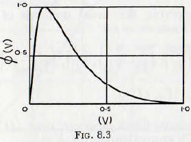
These conclusions are confirmed by the practical observations of Engels that for the grinding of soft materials a hard mill body and balls should be used, but for grinding hard materials a soft but tough metal should be used for the grinding surfaces. Similarly, the curve of Fig. 8.3, is confirmed by Smith, who states that it is well known to mill operators that an improved fineness, in a given time, is attained when the quantity of powder in the mill is reduced, but that this improvement is obtained at the expense of increased iron wear.
In order to analyse the various published data, advantage may well be taken of the simplification offered by the method of dimensional analysis and this will be used as a basis of the subsequent treatment.
It would be expected that the total wear of metal, W, lb, would depend upon the relative hardness of ball and particle, H, upon the size of mill, ball and particle, D, d and b respectively, upon the length of the mill, L. upon the speed of the mill, N, and upon the density of the ball material, q. It would also be expected to depend upon Em, the energy necessary to increase the surface of the metal by unit amount, upon the mill filling, J, upon the fractional volume of the powder, V, upon the pulp consistency, U, upon gravity, g, and upon the time of milling, t.
This may be written symbolically as
Wt = ∅{D, d, b, L, Η, Em, q, Ν, g, t, J, V, U} ………………. (8.1)
and, after applying the usual methods of dimensional analysis, this leads to

This can be simplified, however: since ( D Ν²/g) is, from equation (3.7), equivalent to (N/Nc)².

First examine the functional relationship ∅1(N/Nc). Data by Coghill and Devaney and Gross relating to metal wear, are plotted in Fig. 8.4, and on the same graph the curve relating the rate of production of specific surface to the group (N/Nc), taken from Fig. 5.17, is shown for comparison. It is at once seen that there is close agreement between the rate of production of specific surface in a mill and the rate of ball wear, insofar as these quantities depend on the speed of rotation of the mill. It is also found that for slow speeds, (N/Nc)< 0.6, the functional relationship can be replaced with reasonable
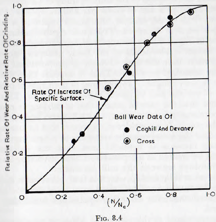
accuracy by ∅1 (N/Nc) =K(N/Nc)1.30 and for the higher speeds, (Ν/Nc) > 0·6 by
∅1(N/Nc) =K(N/Nc)0.8
The decrease in the rate of ball wear at higher speeds would be expected since, whilst decreasing the tangential motion, the cataracting would increase the frequency and intensity of impacts which would promote armouring. As the centrifuging condition is approached the number of balls in action decreases, which again would reduce ball wear. Thus the curve of Fig. 8.4 appears to be of reasonable form.
The close agreement between the points and of the curve of Fig. 8.4 suggests that the metal wear per unit increase in surface attained should be approximately independent of the speed of the mill. A study of Chapter 3 also shows that, for a mill of given size and for speeds of up to about 70% of the critical, the power input to a mill is proportional to the speed of rotation. Again insofar as the curve of Fig. 8.4 may be replaced by a straight line over this range, it also leads to the fairly generally accepted conclusion that the rate of wear is proportional to the power absorbed in a mill. Thus it appears that the ball wear is, very roughly, proportional to both rate of production of surface and to power input to the mill. This also implies that the rate of production of surface is roughly proportional to power input; which has also been deduced in Chapter 6. It is considered, however, that to attempt to calculate the metal wear by reference to power input or to surface increase is artificial and that the calculation should be treated as a separate problem involving its own relationships between the mill parameters.
The next relationship which is fairly obvious is ∅6(L/d) since the total rate of ball wear must vary directly as the length of the mill; all other quantities remaining unaltered.
Turning now to the group (Em/D²qg) it would appear that, on logical grounds, the relationship must take the form
(Wt/D³q) = K(D²qg/Em) …………………………….. (8.4)
since, all other things being equal, the total wear, W, must be inversely proportional to the value of Em. Unfortunately there is no evidence against which this relationship can be tested directly.
Turning next to the function ∅5(b/D)) there are limited relevant data by Mortsell which suggest the general form of this relationship. These data are plotted in Fig. 8.5 and it is seen that the curve has a sharply defined maximum. The probable explanation of the form of this curve is that the “armouring” becomes less effective but the abrasion increases with increasing particle size until the maximum is reached. After this, even though the “armouring” is still ineffective, the particles separate the metal surfaces, acting rather like ball bearings, and so, mill increasing size, reduce the abrasive wear of the metal. It should be noticed that, for the right-hand branch of the curve, which is the practical range, wear varies approximately inversely as (b/D) or, thus, directly as (D/b), and so with the mill diameter. Conversely, for the left-hand portion of the curve the wear varies almost
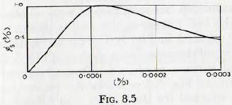
exactly as (b/D); or thus as (D/b)-1.0. The left-hand branch is clearly for large balls grinding a fine powder and the right-hand side is for small balls with coarse material present.
Considering next the effect of relative hardness on the rate of ball wear; a theoretical relationship has been presented in Fig. 8.2. Data for the checking of this relationship are almost completely lacking, but a few values of ball wear, for different Brinell hardnesses of ball, published by McLeod are plotted in Fig. 8.6. This curve shows the general form of Fig. 8.2, but definite correlation cannot be made since very mixed minerals were milled and the corresponding mineral hardness is unknown. Thus, in the absence of more complete data it must be assumed that the curve of Fig. 8.2 represents this relationship.
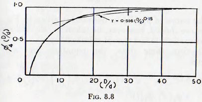
The influence of the ratio of mill size on the rate of wear ∅4(d/D) can more conveniently be written in the form ∅4(D/d), and in Fig. 8.7 are plotted the data of Coghill and Devaney and Gross, relating to the wear of balls when the charge consists of balls of uniform size, and of McLeod, relating to the wear of balls of size d in a charge consisting of balls of mixed sizes. A simple change of the vertical scale of these curves brings them into coincidence and so they may be generalized into the curve of Fig. 8.8, this curve representing the function ∅4(D/d) insofar as it may be derived from these data. It is also seen from this figure that, over the practical range of 10<(D/d)<50, the function may be replaced by ∅4(D/d) = 0.556(D/d)0.15 with an error of less than about 10 %
The relationship between rate of wear of the metal surfaces and the ball charge in the mill is shown by the data of Gross, plotted in Fig. 8.9. This curve is seen to be, very roughly, of the same form as that of Fig. 5.18, relation to the total surface produced. The agreement with the general form of Fig. 3.5 relating the power input to the mill, is not so good for the higher mill fillings; the rate of metal wear being much higher than the power input. This observation is in accordance with the hypothesis of “armouring” since, with high mill fillings the balls are constrained to roll, with considerable abrasion, but impact, which leads to effective armouring, is suppressed.
The only data relating to the effect of the quantity and consistency of the pulp on the ball wear appear to be those of Gross. Unfortunately, these are insufficient in form the basis of a complete analysis.
Furthermore these data appear to be defective in that they are based on run of 21 minutes duration and it appears that this period is insufficient to allow equilibrium to be reached; that is for the armouring to have become established. However, in the absence of more complete data these must be accepted tentatively. It appears that, as a first approximation, the effects of both pulp quantity and pulp density can be stated in terms of the volume of solid material present by


use of the function (V) where, as before, the quantity V is defined by
V = Volume of particles + Volume of space between the particles/Volume of space between the balls (or rods)…………………….. (8.5)
 |
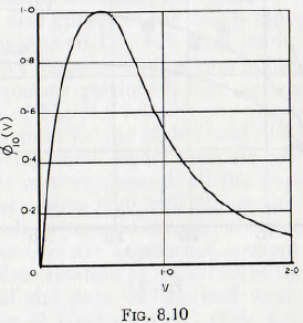 |
and the curve of ∅10(V) so deduced is given in Fig. 8-10. This curve should, however, be taken as only the roughest approximation to the actual relationship.
Collecting these data, the equation for ball wear becomes

where ∅1(Η) is read from Fig. 8.2,
∅3(Ν/Νc) is read from Fig. 8.4,
∅4(D/d) is read from Fig. 8.8,
∅5 (b/D) is read from Fig. 8.5,
∅7(J) is read from Fig. 8.9,
and, ∅10(V) is read from Fig. 8.10.
If now Em and q are regarded as sensibly constant for any steel used in the manufacture of balls and liners and if ∅1(D/d) is replaced by (D/d)0.15 and ∅5(b/D) by (D/b), which may be done over the practical range of these variables, then equation (8.6) becomes

In practical milling the ball diameter is usually approximately a constant multiple of the particle diameter sο this equation becomes

If the relative hardness, Η, the mill filling, J, and the ratio of solids, V, are maintained constant then from the relationships ∅1(Ν/Νc) =K(N/Nc)1·30 for low speeds and ∅1(Ν/Νc) =K(N/Nc)0·8 for high speeds, this relationship becomes:
For low speed,
![]()
and for high speeds,
![]()
The number of balls in the mill ∝ D²L/d³ so the wear per ball Wb is given by
For low speed,
![]()
and for high speed,
![]()
These equations should be contrasted with those of Hukki:
For low speed,
Wt = KD2·5 (N/Nc)d-1.0Lt …………………………..(8.11)
and for high speed,
Wt = KD2 ·5(N/Nc)Lt ……………………………(8.11a)
which lead to:
For low speed
Wb = KD0·5(N/Nc) d²t………………………..(8.12)
and for high speed,
Wb = KD0·5(N/Nc) d³t………………………….(8.12a)
For low speeds the present equation is in fair agreement with that of Hukki insofar as ball diameter is concerned, but at high speed, and in all other respects the agreement is not so good.
The formulae of Hukki are, however, derived from first principles on the basis of clearly defined assumptions. These assumptions are that, for slow speed, the rate of wear is proportional to the rubbing velocity and, for high speed, the wear is proportional to the force of the blow. The first assumption appears to be quite reasonable but the second is not so free from objection. In the first place, the question of the comminution of a material by a blow is involved, and this has already been shown to be a complicated question. Even, however, if the damage is assumed to be proportional to the intensity of a single blow, the “armouring” of the ball surface, and also any work hardening of the metal, would be expected to reduce the rate of ball wear at high speeds.
Having regard for the general uncertainties in the data studied, the equations can be simplified to, for all speeds,

An equation given by Mortsell, for the rate of metal wear, is

where Mb is the total weight of balls, Wt’ is the wear per unit time, d is as before and K is a constant which generally fills between 9 and 16 for Swedish ore but, in extreme cases, between 5 and 23; Wt’ being in kilograms per hour and Mb in metric tons.
Since Mb ∝ D²L it follows that, from this equation, the total wear is proportional to D²; not to D4.65 as suggested previously.
It is interesting now to examine equations (8.13) and (8.14) in the light of the published results of the various authorities.
Firstly, it has been suggested by Davis, that the rate of wear of an individual ball is proportional to d³. But Ellis, Prentice, Garms and Stevens, Norman and Loeb and Norquist and Moeller state that the rate of wear is proportional to d². Furthermore Bond gives various figures, such as 2.0, 2.21 and 2.29 whilst Taggart gives 2.0 for cascading balls. Thus, on this point, the results of the present analysis are roughly in agreement with the view of the majority of other workers, but more work is required before this question is settled.
The question of the influence of the mill diameter does not appear to have received more than passing study but the suggestion that the ball wear varies as D2.6, where D is the mill diameter, appears to be reasonable. A serious criticism of all the work cited is that no effort appears to have been made to maintain similarity between the various tests. The most satisfactory type of equation would appear to be equation (8.6) and, whenever possible, the results should be presented in this, or similar, form.
Since, however, the balls are invariably of iron or steel the value of Em and q may be regarded as sensibly constant, so the equation may be reduced to

An effort has been made to calculate the value of K in this equation, on the basis of the various published work, augmented with reasonable assumed values where necessary, and these values are given in Table 8.1; all values in C.G.S. units.
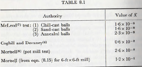
The values calculated from equation (8.16) show fairly wide disagreement but this is not surprising since values for many of the parameters have been assumed. It appears, however, that K= 1.6 x 10⁻⁸ with an error of about ± 50%. Thus it appears safe to conclude that the foregoing analysis includes the major factors in the mechanical wear of balls and liners and it is possible that it can form an adequate basis for an extended and improved treatment.
It should also be pointed out that corrosion has an important effect on the rate of liner wear. Thus, if corrosive substances are present, the products of corrosion will be removed from the working surfaces by abrasion and new metal will be constantly exposed to chemical action. The wear arising from this cause will be proportional to the area of metal exposed, but there is insufficient data for an analysis of this problem.
