The writer of this paper will realizes that the majority of engineering and metallurgical works have from time to time evolved mechanical devices which are of great value as regards application in an operating plant.
Many of these devices would not be apparent to an individual making a brief inspection of works such as these, and it is for this reason that the writer proposes to outline a few of the devices which have been evolved by the engineering department of the Broken Hill Associated Smelters Pty. Ltd.
NOVEL METHOD OF MACHINING A SPHERICAL JOINT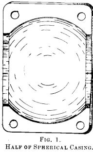
Fig. 1 represents one half of a casing for a ball-joint coupling. In the ordinary methods of boring an external spherical casing, that is with a radius bar attached to the tool rest of a lathe, there is always an error in the bore. It has two flat sides, and this error is inherent in the ordinary orthodox method and cannot be corrected.
The engineers of the Broken Hill Associated Smelters Pty. Ltd. undertook a job that had to be extremely
accurate, and the tool shown in Fig. 2 was evolved. The tool is not exactly fool proof, but in the hands of an average mechanic an absolutely perfect sphere can be bored. The casing has to be held in the lathe in such a manner that one half can be removed without affecting the setting of the work. The business end of the tool is then placed inside the remaining half case and the shank is gripped in the slide rest of the lathe. The tool point must be set exactly on the vertical centre-line of the lathe and the revolving disc set central. The half casing that has been removed can now be replaced on the job. 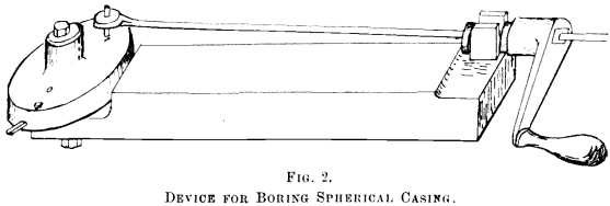 By rotating the handle the disc is revolved on the central pin and the inserted tool will cut an exact sphere, the diameter of which can be varied by moving the cutting point outward until the correct size is obtained.
REINFORCED CASTINGS.
A deal of trouble was once experienced with the cast-iron pallets on the Dwight & Lloyd machines. Owing to the hard knocks they receive when they go over the tip end of the machine they frequently fracture and parts of the pallets find their way into the sinter crushers and cause a lot of damage. This trouble has been almost entirely eliminated by placing a mild-steel bar through the mould in which the pallet is cast and running the metal around it. This method of reinforcing castings is shown in Fig. 3.

It is not claimed that any additional strength is given by the use of the reinforcing bar, but it is claimed that the trouble was cured. The pallets can crack now in three or four places but they are held together like a lot of beads are held on a string, and go on with their work as well as ever.
There are a few points in connection with this that are worth knowing. It is essential that all moulds are thoroughly dry before being poured, because if damp sand is used, drops of moisture form on the reinforcing bars and blow-holes are the result. The most successful results seem to be obtained when the relative proportions of the cast-iron and the reinforcing bar are about 5 to 1. Clean bar stock must be used for reinforcing. If rusty, it must be put through a rumbler.
ELEVATOR BUCKET
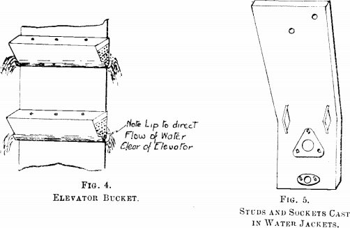
Fig. 4 represents an improved type of elevator bucket. It was found that the ordinary buckets elevating solid material, viz., granulated slag, from under water, were simply draining from one bucket to another. One of the engineers, Mr. Tonkin, made and installed buckets shown in Fig. 4. The projecting lip at each end should be noted. This idea effectually cured the whole bother and incidentally reduced the load on the motor.
CAST-IRON WATER JACKETS
Fig 5 represents one of the water jackets. These jackets are standardized. They have 5 studs and 2 water-pipe connections in each.
Two of the studs are for the cleaning door, the other three are to hold the tuyere casting. The water connections are for 1½-in. pipe and are for inlet and outlet of the cooling water. The jackets weigh about 7 cwt. each, and at one time lumbered up the workshop very considerably, as it was the practice for a long time to drill and tap the stud and pipe holes. For some time past these stud and pipe connections have been cast in the jacket and have saved endless trouble. The jackets are never inside of the workshops now.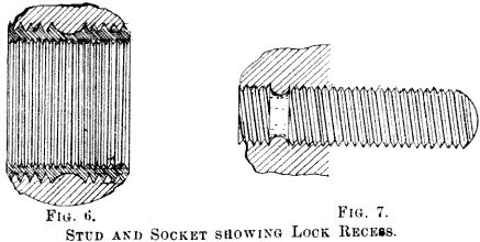
At first a little brother was experienced with the stud and pipe sockets. If they were twisted too hard they would loosen. A recess is now cut in the part that is cast in the jacket, and this effectually locks them. They can neither back in or out of the casting. These recesses are shown in Figs. 6 and 7.
TUYERE CASTING
Fig. 8 shows the poke-hole end of a tuyere, with cap removed. The cap is run on a fast thread ¾ in. pitch, and this thread, and also the female thread in the cap, are very successfully cut by the moulder in the sand.
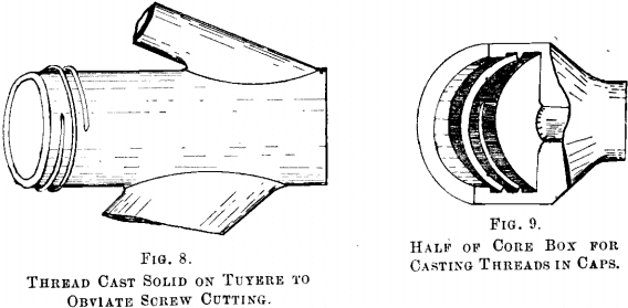
Fig. 9 is a view of one half of the core box used.
MANDREL FOR USE IN RUNNING BEARINGS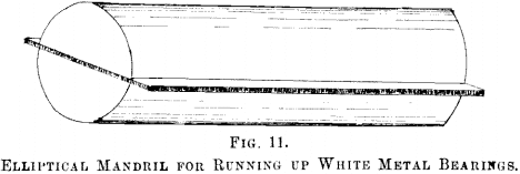
Fig 10 represents a mandrel used for white-metalling bearings. The fine in the centre is made to fit between the cheeks of the bearing and the cap is then bolted down in place. Both top and bottom halves are then run in one pour. The mandrel is then removed and no further work, except cutting oil races, should have to be done on the bearing. This type of mandrel in all sizes of bearings from 1½ in. to 4 in. is used, and no trouble is experienced with it.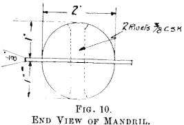
USEFUL MODIFICATION OF EMPTYING COCK ON OIL DRUMS
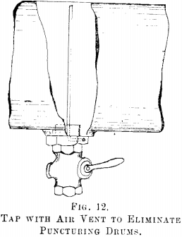
Fig. 12 shows how a troublesome job was saved by one of the engineers, Mr. Tonkin. The works used hundreds of drums of crude oil. These drums had one screwed connection on them for filling and emptying, A vent hole had to be punched in the drums and subsequently soldered up. Fig. 12 illustrates the method of admitting air without a vent hole. A small tube rivetted in the emptying cock and projecting up to the top of the drum effectually solved the problem.