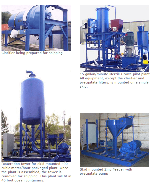
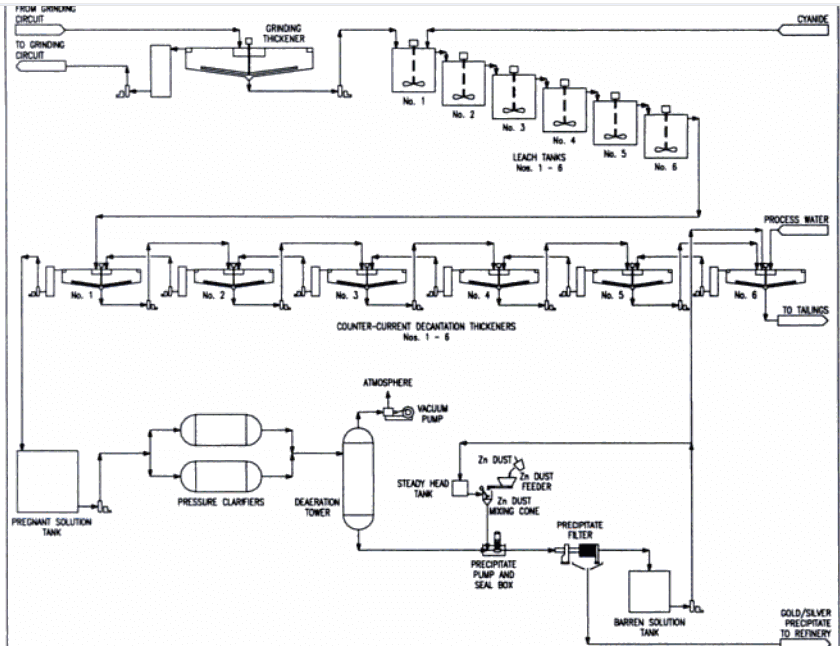
 The Operation of a Merrill-Crowe Zinc Precipitation circuit requires for Preparation for its Startup that the following items be checked before the equipment in the Merrill-Crowe Zinc Precipitation Circuit is started.
- Note the levels in the pregnant solution, clarified solution and barren solution tanks. The pregnant and barren solution tanks should be approximately half full. If the pregnant solution tank is full and the barren solution tank close to empty, the Merrill-Crowe Circuit may have to be the first area of the plant to be started.
- Check that power is available to the equipment and that all equipment that has been subjected to maintenance is unlocked.
- Check that the zinc feeder is full and operational, and the lead nitrate tank has adequate stock.
- Check any major equipment to be used for readiness, particularly the precipitate presses and clarifiers. Also, check that the proper valves are adjusted for the operation of the desired clarifier and filter press.
- Check vacuum pump and seal water status.
- All valves should be closed before start up.
Merrill-Crowe Zinc Precipitation Circuit Start UP Sequence
Start up of the Merrill-Crowe Circuit should proceed when thickener overflow or filtrate flows to the pregnant solution tank.
- Start the clarifier feed pump.
- Adjust the appropriate valves in the clarifier inlet manifold to allow pregnant solution to enter the clarifier and to take the clarifier discharge pump off recirculation.
- Open the butterfly valve on the vacuum line to the deaerator.
- Start the deaerator feed pump.
- Start the precipitate filter feed pump and ensure that the pump gland seal tank is full of barren solution.
- If it is not already running, start the barren solution pump.
- Start the zinc feeder and lead nitrate metering pump and ensure that barren solution is flowing to the zinc mix tank.
- Turn on the timer on the pregnant solution sampler and the barren solution sampler.

Normal Circuit Operation
After the Merrill-Crowe Zinc Precipitation Circuit has been brought up to normal operating conditions, the operator must monitor the various process variables and alarms. The operator is also required to sample and analyse process streams and read local indicators.
The major difficulty in operating the Merrill Crowe zinc precipitation circuit is keeping the flow through the various parts of the circuit equal. This is complicated by the non-continuous nature of some of the processes (clarification and precipitate filtration) and by the tendency of the various process unit steps to have a significant variation in capacity over the operating cycle. This requires the operator to continually monitor equipment operation and anticipate process requirements.
Clarification
Depending on the solids content of the pregnant solution, the clarifiers will have a long or short operating cycle. If the pregnant solution is exceptionally dirty (i.e. high solids content), the operating cycle of the clarifier will become quite short. The thickener operator and the filter operator must be made aware of the problem as early as possible to prevent clarifier operation from limiting production.
The normal maximum operating vacuum on the clarifier is 18″ Hg. As the unit approaches this vacuum it is an indication that the unit will soon require cleaning. Monitor the vacuum pressure gauge to determine loading on the clarifier leaves. When the 18″ Hg vacuum is achieved, the pressure switch will alarm and. shut down the respective clarifier discharge pump. At this point the standby clarifier must be put into operation.
Another reason for changing clarifiers is when the clarified solution indicates solids breakthrough even before the 18″ Hg vacuum limit is reached. This condition may be caused by a poorly or unevenly precoated clarifier leaves.
On the other hand, if the clarifier leaves are for some reason blinded and the unit is unable to pass sufficient solution to keep the system in balance (i.e. a vacuum of less than 18″ Hg is sufficient to diminish the pumping rate of the clarifier feed pump to a level where trouble is anticipated). The clarifier must be taken out of service and the cleaning cycle initiated.
The full clarifier must now be cleaned.
The sluice launder valve must now be opened and the contents (mainly solution) drained to the filter feed pump box.
The clarifier spray bar motor is started as is the backwash sprays. The spray bar motor is interlocked with the solenoid valve in the wash water (barren solution) line. The solids are washed off of the filter leaves and sluiced into the thickener. When all of the solids (dirty precoat) on the clarifier leaves have been washed off, the spray bar motor is stopped and the spray water solenoid valve is automatically closed. The clarifier tank is drained and the sluice valve is closed. The clarifier is then ready to be precoated.
Deaeration Crowe Tower
The deaeration tower is run under high vacuum. The deaerator feed pump should be running to give a slight excess of feed to the deaeration tower so that the tower operates with a solution level part way up the level sight gauge glass.
The addition of zinc dust to the deaerated solution is the most important factor for gold and silver recovery. Without the zinc dust, the gold and silver will remain in solution and will not be recovered in the precipitate filter press. Therefore, the operator must ensure that there is an adequate and continuous supply of zinc dust being added to the deaerated solution. The optimum amount of zinc to be added will be determined with operating experience, however, a slight excess of zinc dust should always be added.

Once the clarified solution is deaerated and the zinc dust added, it is imperative that no air be drawn into this part of the system. This explains the design of the zinc mix tank and the flooded pump gland tank on the precipitate filter feed pumps. The operator must ensure that the liquid level in both tanks is maintained at all times to prevent air entering the system.
Zinc Precipitation
Normally only one precipitate filter press is in use while the other is on standby. However, provision is made to operate both presses in series at one time. The precipitate feed pressure should be monitored as an indication of the loading condition within the press. The main items for the operator to ensure are:
- The barren solution from the press is clear. This can be checked regularly by taking a small sample from the barren solution line.
- There is no dissolved gold or silver in the barren solution. If there is gold or silver in the barren solution, indicated by the routine
analysis, the first step is to increase the zinc dosage rate. Check the zinc feeder hopper to make sure it has not run out of zinc or is not plugged. Also check that lead nitrate is still flowing. - That the press is not leaking. A leaking press will result in losses of gold and silver. The operator must ensure that the press is closed and sealed properly. The filter press is closed with the hydraulic cylinder. When the hydraulic pressure gauge reads 4800 psi (34,500 kPa), adjust the locking nut on the cylinder to lock the press closed. Once the cylinder is locked, release the hydraulic pressure. If the press begins to leak after it has been operating for some time, the press must be immediately taken out of service and replaced with the standby press.
The cycling, cleaning and precoating of the precipitate filter presses was previously discussed in detail.
The barren solution is continuously and automatically sampled with the solenoid valve timer, however, the operator should routinely check these samples to ensure that barren solution clarity is maintained.
Merrill-Crowe Normal Shutdown Sequence & Procedure
It is preferred on shutdown, that as much solution as possible be in the barren solution tank and as little as possible in the pregnant solution tanks.
On an orderly and routine shutdown of the plant, this circuit should be left running as long as possible to maximize the amount of barren solution in the barren tank.
- Stop the clarifier feed pump and, if flocculant is being added to the clarifier feed line, shut off the flocculant metering pump.
- Turn off the appropriate clarifier body feeder and close the shut off valve in the barren line to the body feeder eductor.
- If the plant is to be shut down for a short period of time, adjust the appropriate valves in the clarifier inlet manifold to put the clarifier discharge pump on recirculation. However, if the plant is to be shut down for an extended period of time, close the shut off valves in the clarifier feed lines and shut off the clarifier discharge pump. The clarifier must then be drained and cleaned prior to restarting the plant.
- Turn off the zinc feeder and the lead nitrate metering pump and close the shut off valve in the barren solution line to the zinc mix tank.
- Stop the deaerator feed pump.
- Stop the precipitate filter feed pump.
- Stop the barren solution pump.
- Shut of the timers on the pregnant solution sampler and the barren solution sampler.

Emergency Shutdown Procedure
In the event of an emergency, all of the equipment in the Merrill-Crowe Zinc Precipitation Circuit can be shut down by locally mounted STOP switches or from the MCC located in the mill control room.
After the equipment is shut down, shut off the lead nitrate metering pump and close all shut off valves in the associated air and solution lines.
https://www.911metallurgist.com/merrill-crowe-zinc-precipitation-circuit-operation
https://www.911metallurgist.com/gold-and-silver-refining
