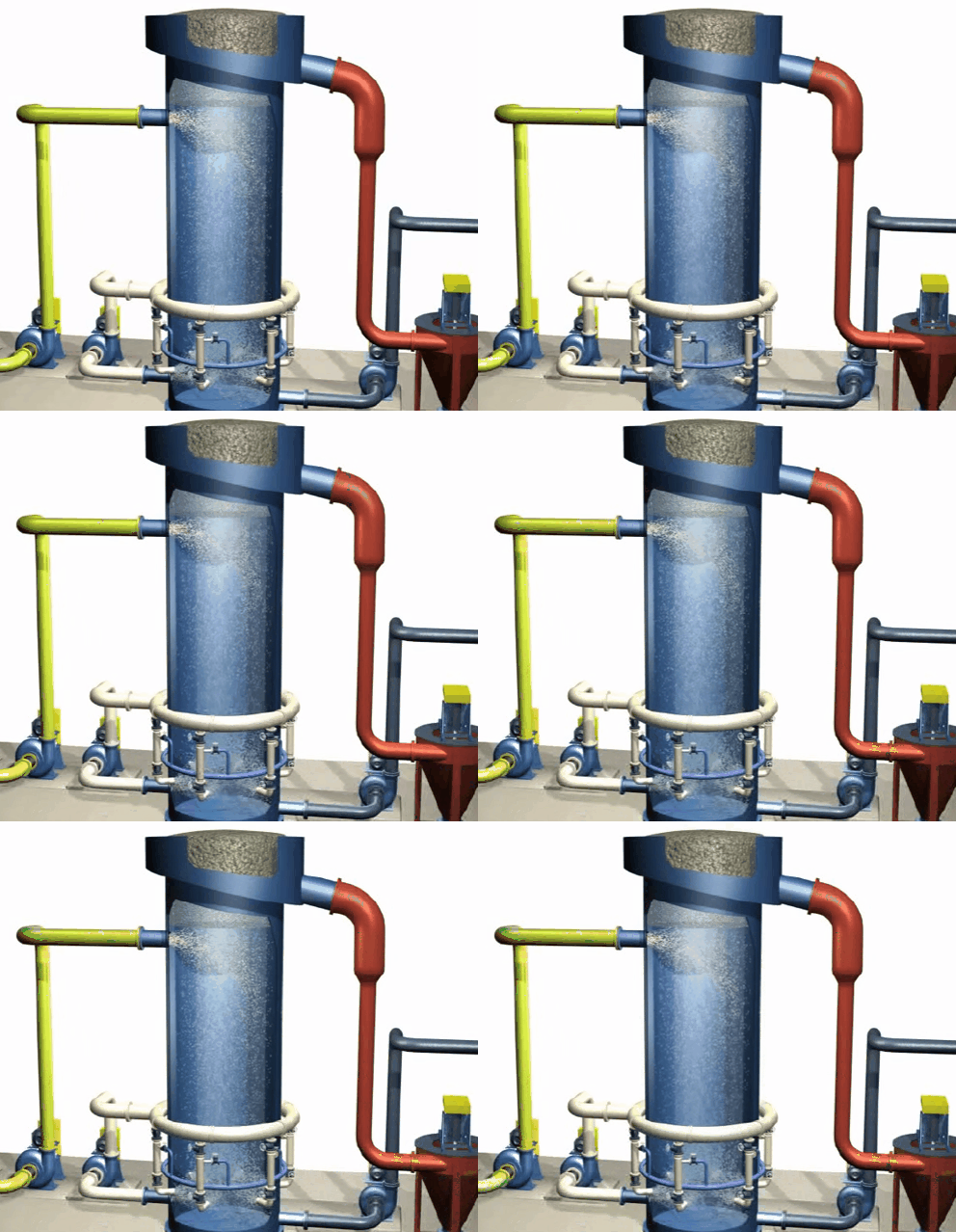
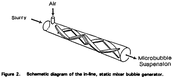
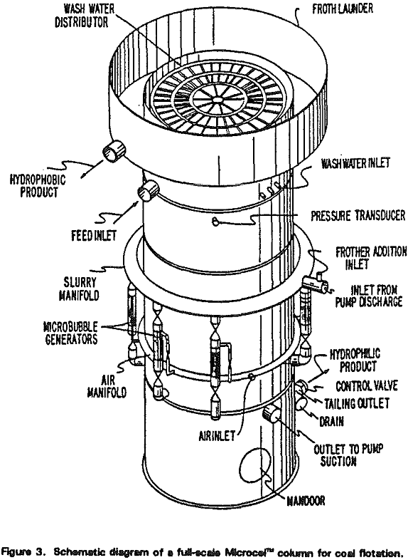
The Microcel™ sparger consists of in-line static mixers and a centrifugal pump. Tailings slurry is pumped from the base of the column through the static mixers, where air and slurry are mixed under high-shear conditions to create the bubble dispersion.
As the air-slurry mixture passes through the stationary blades located inside the mixer, the air is sheared into very small bubbles by the intense agitation.
ERIEZ Flotation Column cells
ERIEZ column cells have a similar system called “Cavitation System”
Flotation of Fine and Coarse Applied to Mineral Recovery Copper by DioniAlvarez on Scribd
Non-metallic Mineral Flotation by Microcel Column
Many investigators have conducted hydrodynamic analyses of the bubble-particle collision process. Conclusions of these studies can be summarily represented by the following equation:

in which Pc, is probability of collection, Dp particle diameter, and Db is the bubble diameter. The coefficient (n) varies with the Reynolds number of the bubble, but is approximately 2 for most flotation size bubbles. Thus, when particle size is reduced, Pc decreases approximately as the square of particle size, providing an explanation for the difficulty in fine particle flotation in general. However, this problem can be overcome by decreasing Db and, hence, maintaining Pc, at a minimum required level.
It can be readily shown that the first-order flotation rate constant (k) is a function of Db and superficial gas rate (Vg) as follows:

Since Pc varies approximately as Db-², as shown in Eq. [1], one can see that k should vary as Db-³ at a given Vg.
Microcel Column
A schematic diagram of the Microcel” flotation column is shown in Figure 1. The basic unit can be subdivided into three zones that are analogous to the rougher, scavenger, and cleaner sections of s conventional flotation circuit.
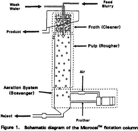
During the course of bubble generation, misplaced hydrophobic particles (or middlings that require longer retention times) are given a chance to make a bubble-particle contact and be floated. The mode of bubble-particle contact is co-current as opposed to the countercurrent flow in the pulp zone. Co-current bubble-particle contacting mechanisms are desirable for fine particle flotation. As such, the bubble generation section works similar to a scavenger bank in a conventional flotation circuit.
Laboratory and Pilot-Scale Testing
Kaolin Clay
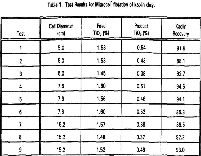
Several tests were conducted at various feed flow rates for each column diameter. Aeration rates ranging from 0.1 to 0.5 cm/s and wash water rates ranging from 0.1-0.3 cm/s were used throughout the test program. As shown in Table 1, %TiO2 was reduced to 0.37-0.61% with very high kaolin recoveries. All the tests were conducted with less than 30 minutes of retention time, which is significantly shorter than the case of using a conventional flotation cell.
Phosphate
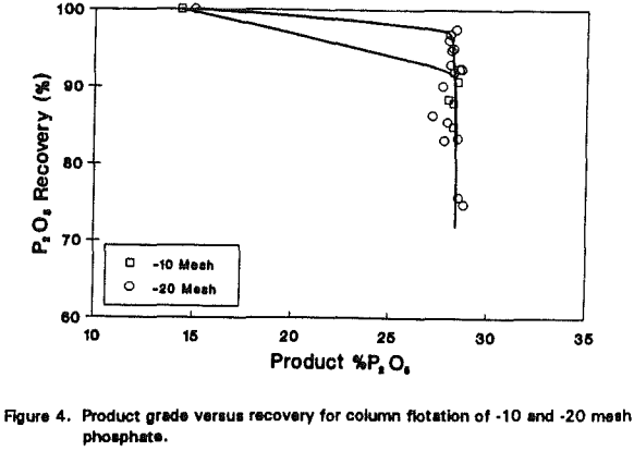
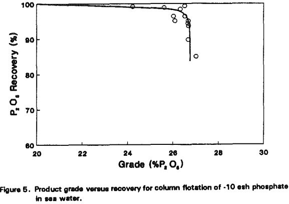
The improvement made with kaolin processing was anticipated since the microbubble flotation column was originally designed to upgrade fine particles. The same technology may be used for coarse particle flotation as well. To test this possibility, several phosphate samples were obtained and floated using laboratory- and pilot-scale columns.
Feldspar Tailing
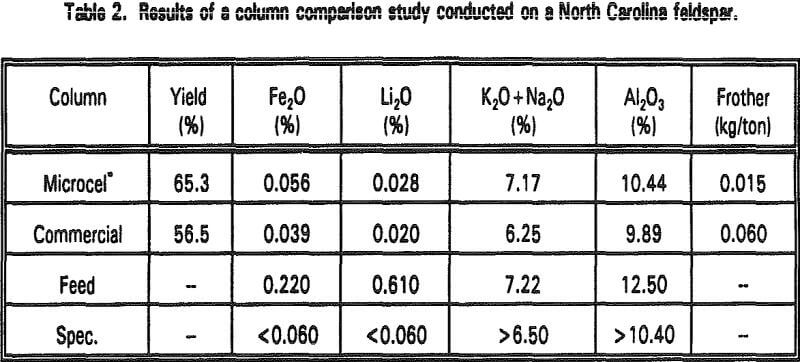
Pilot-scale flotation tests on a feldspar tailing were conducted at the N. C. State University Minerals Research Laboratory in Asheville, North Carolina. Table 2 compares the results obtained using a Microcel column with those obtained using another commercial flotation column. Both columns were 8 inches in diameter and approximately 15 feet long. Feed, aeration, and wash water flow rates were maintained at similar levels in each unit for direct comparison.
Graphite
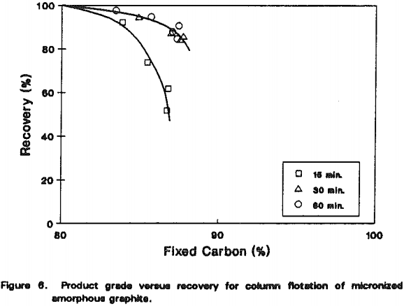
An amorphous graphite ore was upgraded using a 5-cm diameter laboratory Microcel” column. The feed was prepared by pulverizing the run-of-mine ore in a hammer mill and wet-grinding it in a laboratory stirred ball mill for 15, 30 and 60 minutes. The mill product was diluted to 5% solids before feeding it to the column at 0.05-1.0 lpm. The wash water rate was maintained at 0.5 lpm and the aeration rate varied from 1.0-1.5 lpm. The Sherex 214 frother was used in all tests at concentrations less than 50 ppm.
