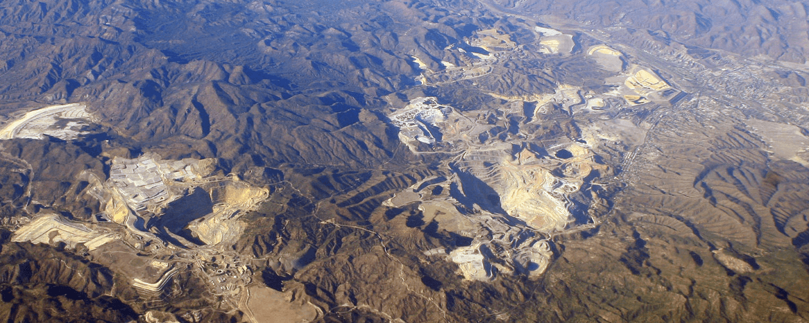
The mines and mining methods of the now defunct Arizona Mining Copper Co. are situated in the Morenci-Metcalf copper district in southeastern Arizona. This copper-bearing district covers a triangular mountainous area of about 3 square miles, rising abruptly from the gravel plateau of the surrounding country. In this area, an immense intrusion of porphyry has displaced, shattered, and engulfed the shales, limestones, and quartzites formerly bedded on the basal granite.
Outcrops of oxide ore were discovered in 1873, and these surface ores were found to connect in depth with large bodies of high-grade oxide ores in the limestones and shales. The smelting of these ores in blast furnaces continued until about 1893, when the rapid exhaustion of the high-grade ore led to the discovery and exploitation of the low-grade sulphide ores in the adjoining porphyry.
Methods of concentration were then devised and the low-grade ores finally rendered profitable. The Arizona Copper Co. and the Detroit Copper Mining Co., operating in the same district, were the pioneers in the successful development of the low-grade “porphyry” properties of to-day.
The largest mines of the Arizona Copper Co. are the Humboldt and Clay at Morenci, and the Coronado, Metcalf, and King at Metcalf. These mines produce about 4,000 tons daily of concentrating ore containing from 2.5 to 2.8 per cent, copper.
The topography of the country is very rugged and mining operations are conducted principally through adit levels. A few of the mines are opened by shafts, the deepest being 1,100 ft., in the Coronado mine.
ORE OCCURRENCE
The low-grade sulphide ore occurs as:
- disseminated deposits in the main stock of quartz porphyry;
- lode deposits in fault fissures in granite.
The high-grade oxide ores were found as tabular deposits in limestone and shale close to contacts with porphyry. Low-grade oxide ore formed the outcrop of some of the sulphide orebodies; the majority of the outcrops, however, were barren.
OREBODIES
Unlike most of the newer low-grade copper mines, the porphyry ore of this district does not occur as one large deposit. The main porphyry stock is broken up by the inclosure of large masses of sedimentary rocks resulting in a number of separate orebodies as dikes. Other orebodies have formed along fault-brecciated areas in- porphyry or in granite, and the rock outside of the influence of the fault is barren or only weakly mineralized.
The diversity in size of some of the orebodies is shown by the following dimensions:

The depth from surface to which the orebodies have been proved to be of commercial value varies from 450 to 800 ft.
MINING METHODS
The method of extracting the ore is dependent upon the nature of the ore occurrence. Each orebody is a problem in itself. All influencing factors, as size, shape, position, nature and grade of an orebody, and character of the enclosing walls, are fully considered before the method of extraction is decided. The ore reserves, though large, are not so immense that mining methods involving a sacrifice of ore or its dilution by waste for the sake of cheaper mining costs have ever been used. The following examples are typical of the mining methods in use.
Open Pit Mining
The oxide ores found close to the surface on Metcalf Hill are extracted by opencast work. The amount of ore available for open work has never been sufficient to justify the large expenditures needed to install mechanical appliances such as steam shovels; hand work has always been employed.
Benches or terraces up to 30 ft. in height are carried into the orebody and the overburden and ore broken alternately. To prevent admixture of ore and cap rock, heavy blasts are seldom used.
The ore or waste is loaded by hand into cars of 25 cu. ft. capacity, or shoveled into chutes brought up from a lower level to the floor of the working place. In this handling of the ore, a preliminary sorting out of waste rock is made and this is completed on the sorting screens erected over the storage bins.
When conditions , permit, mill-holing is used for the more rapid removal of the waste or ore.
The fluctuations in output of ore caused by the alternate handling of overburden and ore are reduced by keeping open a large number of working places.
If the orebody has been proved below the depth of economical open work, disposal of the overburden can be economically made by using it as filling material in stoping the ore on lower levels.
The dry climate and mild winters are favorable factors to opencast mining in Arizona.
Open Stoping and Filling
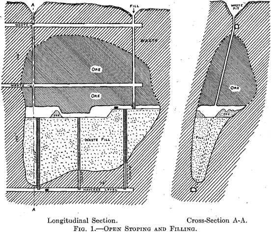
Where the ore is hard and stands well, a system of open stoping without timber is employed with subsequent filling. (Fig. 1.)
The bottom of the oreshoot having been determined, it is opened for its full length and width and to a height of 15 to 20 ft. While this is proceeding, one or more raises are driven to the surface or to the level above for ventilation and waste filling. Chutes and ladderways are then erected from the tramming level and the stope filled with waste to within 8 ft. of the roof. Slices of from 15 to 20 ft. in height are then mined overhand along the whole length of the oreshoot, and waste filling follows behind the working face. The filling is best distributed from the waste chute by means of a light car on a movable track. Mechanical means such as scrapers have not proved successful. Excepting a few log cribs or square sets placed beneath loose portions of the roof, no timber is used.
Where the orebody is on or close to an important tramming road, stoping is started above the level of the road and a shell of ore 10 to 15 ft. thick is left to protect the roadway.
Several stopes in Metcalf mine worked by this method were so wide (up to 300 ft.) that pillars representing about 5 per cent, of the orebody were left to support the roof. If waste filling is cheaply obtained, either from surface stripping or from glory holes, the system is very economical, but the danger to the men from the unsupported roof limits this method to only the best standing ground.
Underhand Stoping
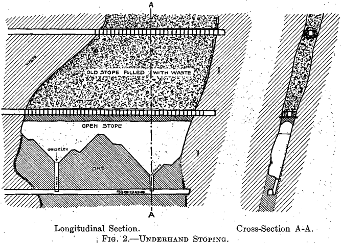
In narrow veins with firm walls, underhand stoping directly into chutes is employed. (Fig. 2.)
Untimbered chutes are carried to the top of the orebody at intervals of 25 to 50 ft. Around the top of these chutes underhand mining commences, the broken ore falling directly into the chute. The working floor is always kept cone shaped to avoid shoveling the broken ore. A grizzly of logs prevents very large pieces of ore from entering the chute.
This method is only practicable under a sound roof, as in the process of stoping the height of the roof is constantly increasing and its observation made more difficult.
Shrinkage Stoping
In this method, the broken ore is allowed to accumulate in the stope to support the walls and form a working floor for mining the roof. Practically no timber is used and the ore is drawn from chutes at the bottom of the stope directly into the mine cars.
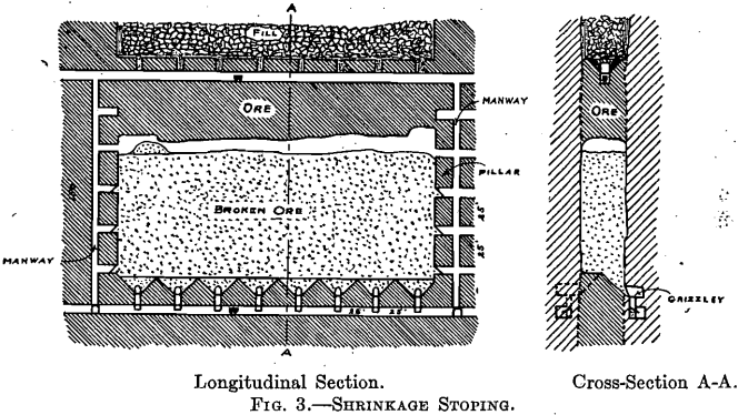
In mining large orebodies shrinkage stoping is generally used in conjunction with top slicing or block caving; the pillars separating the shrinkage stopes necessitating the use of either of the foregoing methods for their removal.
The application of this method at the Coronado mine is shown in Fig. 3. The vein is about 35 ft. wide and is stoped in lengths of 150 ft. with pillars 30 ft. long between the stopes. The overhand mining is confined to the ends of the stope with the object of leaving a sag or belly in the roof of the ore. This finally breaks off by its own weight and, if it does not break by its fall, it is “bulldozed” on top. As stoping progresses, about one-third of the broken ore must be drawn out to allow working space below the roof. Should the roof become dangerous to work beneath, the ore can be broken down by underhand stoping from a sub-level driven 25 to 30 ft. above the stope. Access to this sub-level is obtained from the ladderways in the end pillars.
The breaking of ore is stopped 25 to 30 ft. below the bottom of the overlying stope and the broken ore then rapidly drawn through the chutes. The old waste filling in the overlying stope is tapped and run into the empty stope. When full and leveled off, the shell of ore left in the roof is gained by square-set timbering. The pillars between the stopes are then removed by top slicing.
The chute arrangement at the bottom of the stope varies in different orebodies. At the King mine, the ore breaks fine and can therefore be pulled directly through the chutes. At the Coronado mine, the ore is harder and cannot be run directly into cars without much block-holing in the chutes. Two different methods are used to allow of the ore being broken by hand. In the first system, haulage roads are run in the foot wall parallel with the orebody and inclined chutes put up at 30-ft. intervals into the stope. Over each chute is a grizzly on which the laborer stands to rake down the ore and break the large pieces passing into the chute. Another system employed is to run a level, timbered two sets high, through the center of the orebody. On the sides of the upper set of this drift inclined raises are made to the floor of the stope which is opened 20 ft. above the level. The broken ore passing through these raises is loaded directly into the cars beneath by opening the lagging on top of the first set.
The completion of a stope depends upon its depth from surface or the condition of the upper workings. If on top of the orebody, the stope can generally be carried to cap rock and then drawn quickly without difficulty. The danger of an air blast from the sudden caving of an empty stope makes subsequent filling always advisable.
Where the roof of the stope is too weak to leave an unsupported shell, the roof is carefully arched and timbered with long heavy stulls from wall to wall, before the broken ore is drawn.
A method was tried of laying a heavy mat of timbers on top of the broken ore, caving the waste above on, top of this mat and drawing the ore from beneath. It was found that if the mat was caused to descend more than 30 ft. it became so broken up that a serious dilution of the ore with waste resulted.
A vital objection to this system developed in the Coronado mine. The ore from this mine contains a larger amount of pyrite than is usual in the district, and when the broken ore was drawn from the stopes it was found to be so highly oxidized that the system had to be abandoned.
Square Set and Fill
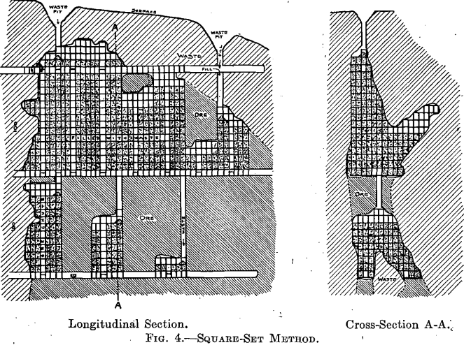
The principal mining method employed for many years in the district was square set and fill. (Fig. 4.)
The expense of using this system in the large bodies led to its disuse and the substitution of top-slicing methods. An excessive amount of timber had to be used in reinforcing the square sets to prevent serious caves, and the maintenance of raises to surface for waste became more difficult as the workings extended.
The square-set method is, however, still employed in the extraction of orebodies of irregular shape and in the first stage of top-slicing. Except in minor details, square-set practice here does not differ from that of other districts.
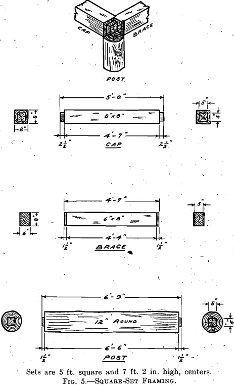
The set of timber comprises an 8 by 8-in. cap, 6 by 8-in brace, and a 6½-ft. round post. The set allows of the extraction of 178 cu. ft., or
14 tons, of ore, and without any reinforcements calls for 8 ft. b. m. of timber per ton of ore. (Fig. 5.)
Waste filling is obtained from raises to surface of to old stopes above and the floors are kept filled to within one set of the roof.
As the high cost of timbering in square-set work is due to the necessity for reinforcing caps and braces that are overloaded, stopes of small floor area are opened and worked rapidly.
A change in the square-set practice has recently been made by using sets 10 ft. high, allowing of the extraction of 250 cu. ft. of ore. The stope posts of 6½ ft. height have been replaced by posts 9½ ft. long; the other set members have not been changed.
The increase in height of the set causes only a small reduction in its strength and reduces the cost of timbering about 15 per cent. In a stope, the weight of the roof is carried by the caps, braces, and lagging and through these transmitted to the posts. The crushing strength of
the 6½-ft. posts is so much greater than the transverse strength of the cap and brace that an increase in the height of the post does not materially reduce the strength of the set.
Sub-Level Caving
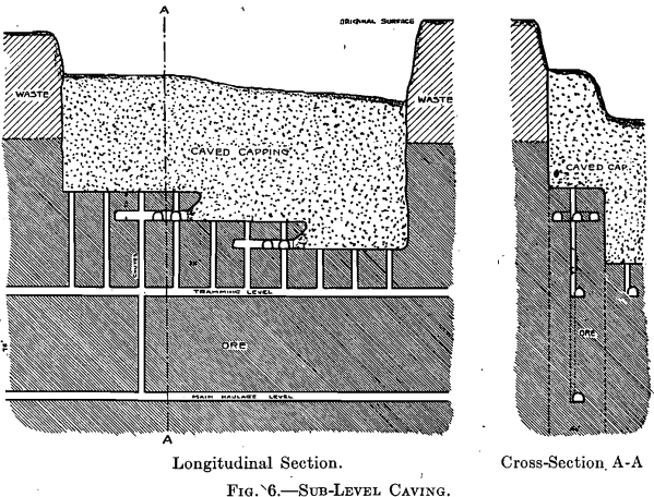
A sub-level caving system is sometimes employed in mining the upper part of an orebody preparatory to top slicing.
The details of the system are shown in Fig. 6. Slices 40 ft. wide are cut up by drifts 20 ft. below the caved ground. The back of ore is mined by retreating and the waste allowed to cave. As no mat is used, the inevitable mixing of ore with waste rock causes a serious fall in the grade of the ore.
Rill Stoping
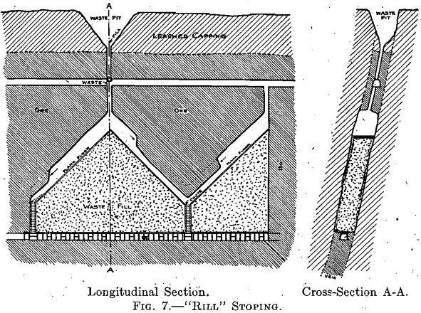
In narrow veins where filling is needed, to support the walls, rill stoping is often employed. (Fig. 7.)
In this system the roof of the stope is worked on an incline and the broken ore runs down the sloping fill directly into the chute. After a slice of ore 10 to 15 ft. in height has been worked out, the stope is cleaned, waste filling run in and mining resumed. Shoveling is eliminated, but the output of ore is necessarily intermittent.
Top Slicing
The top-slicing method is principally used in the extraction of the large, soft ore orebodies of the Humboldt mine. The system is an appli
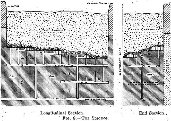
cation of longwall retreating of the coal mines, worked under an artificial roof of timber called the “mat.” (Fig. 8.)
The top of the orebody is removed either by open stoping, square setting, or sub-level caving and a double floor of 2-in. plank laid. The overburden is then caved on top of the mat, either to surface or sufficiently high to make it safe to work beneath the mat.
A tramming level is laid out 55 ft. below the mat and divided by drifts into blocks of 30 to 40 ft. in width. At intervals of 25 ft. along these drifts, timbered raises divided into chutes and ladderways are carried up to the mat above. Commencing at the boundary of the ore, slices 11 ft. in height by 30 or 40 ft. in width are mined beneath the mat, which is temporarily supported by sets with posts 10 ft. high and round unframed caps. As the slice advances, a layer of 2-in., plank is laid on the floor, lengthwise with the slice, and the timber mat is caved by blasting the posts behind the working face; only sufficient space is kept open under the mat to permit of shoveling into the chute. Connection is made between the chutes by driving a tunnel ahead of the slice. This tunnel may be small and untimbered or carried the full height of the slice and timbered with 10-ft. sets to support the mat.
From the drift chutes, the ore is transferred by hand tramming in cars of 21 cu. ft. capacity to the motor chutes on the main haulage roads.
Top slicing allows of a more regular and larger output from a working breast than square setting. The breaking and shoveling of the ore is, however, not so advantageous as in square sets; the working face not being undercut and the shoveling being done on a rough floor. The weight of mat is heavy but fairly constant and sudden caves are exceptional. Owing to the smaller working space that must be kept open, the consumption of timber is less than with square sets.
To allow the broken ore at all times to be shoveled directly into the chutes, the following modification has been made: When the working face has advanced so far that the ore cannot be shoveled directly into the chute; the men are transferred to the next chute, and a new breast is opened and worked on all sides. In slices 30 ft. wide and with chutes 25 ft. apart, this system always permits direct shoveling and avoids the use of wheelbarrows.
Panel Slicing
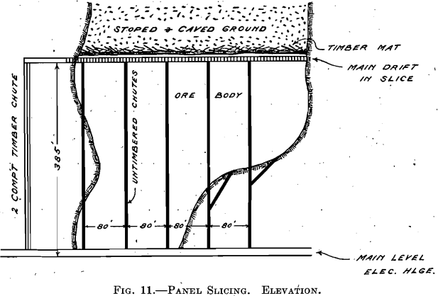
To eliminate the heavy expense of installing and maintaining chute raises every 25 ft. in the slices, a system whereby the ore will be loaded into cars directly in the slice is about to be tried out. In this system, which has been called “panel slicing,” all of the working faces and all tramming will be on the same floor and the use of tramming levels at 55-ft. intervals will be abandoned. (Figs. 9, 10, and 11.)
The working level will be divided into slices by crosscuts every 40 ft. along the main road. The main road and the parts of the crosscuts
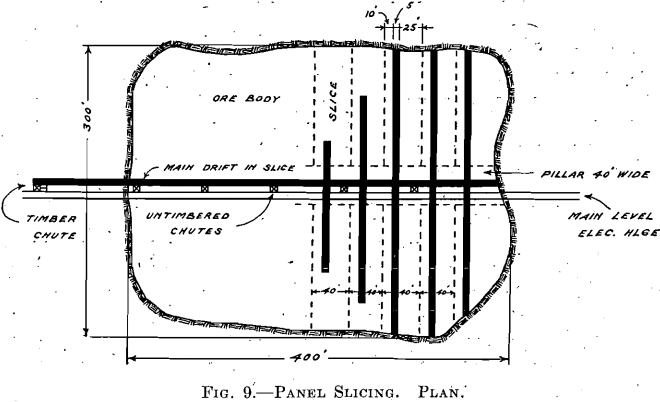
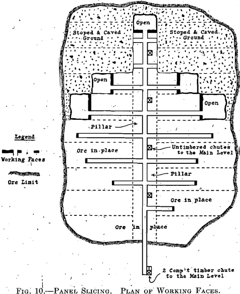
forming the main road pillar 40 ft. wide will be timbered with sets 6½ ft. high. Outside of this area, the crosscuts will be opened through to the mat above and timbered with slice sets 10 ft. high. Slices 40 ft. in width will then be worked from the margin of the ore toward the pillar over the roadway. This pillar will not be removed until the slices on each side of it are exhausted.
Ore chutes spaced at 80-ft. intervals along the main level receive the ore trammed from the working faces.
As one floor or panel is being worked, the next one, 11 ft. below, will be in preparation.
Drilling and Blasting
Air drills are employed almost entirely in mining. Air at 100 lb. pressure is supplied by two Nordberg compressors of 4,000 cu. ft. total capacity, direct connected to two alternating-current motors. One compressor at Morenci supplies the Humboldt and Clay mines; the other at Coronado supplies the King and Coronado mines.
One-man machines of various makes are used throughout. In slicing, “jackhamers” are used in soft and water Leyners in harder ground.
Giant ammonia powder of 30 to 40 per cent, is used in blasting, 1-lb. of powder breaking from 7 to 10 tons of ore. Prepared primers are issued to the miners from a number of supply magazines in the mine.
Timber and Timbering
Oregon fir costing about $24 per 1,000 ft. is used for all square timbers, round timbers being of Texas pine costing about $19. Round timber, being stronger and cheaper, is used wherever possible. In temporary timbering, such as in top slices, cheap cull lumber is used.
The standard sizes of timber sets are cut by a double-end framer at the terminus of the standard-gauge railroad at Clifton, before shipment to the mines.
Holman air hoists are used in handling the timbers to the stopes.
The dimensions of the timbers employed are as follows:
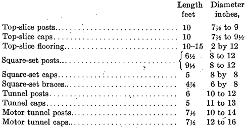
The consumption of timber in top slicing, including chutes, ladders, and reinforcements, is about 9. ft. b.m. per ton and in square-set work about 15 ft. b.m. per ton.
The objective of the committee is to prepare a symposium on mining methods which will be of real practical value to the operator and engineer in the solution of every-day mining problems. It is planned to cover the entire field of mining in such a way that the different branches of mining, such as coal and ore (iron, copper, lead, zinc and precious metal) can benefit from the experience of the others at points where they have problems in common. . It is realized fully that each of these branches of mining possesses its own peculiar problems, but at the same time, there are problems in connection with each, where the experience in others should be of value. The committee proposes to proceed along the following lines:
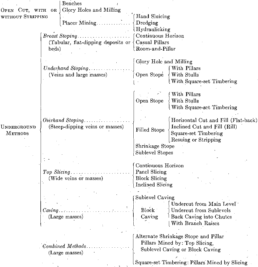
- To present a general classification of mining methods, showing their inter-relationship, and at the same time provide a common language for the discussion of mining methods and a nomenclature that will have the same meaning wherever used. A complete set of illustrations will accompany the classification to make clear the terminology adopted and to show graphically the inter-relationship of methods.
- To show the relationship between the physical characteristic of the deposit, the economic considerations and the mining method. It is not proposed to treat this subject as a mere academic problem, but to secure reports from every mining company of importance in this country, which will show what methods or modifications and combinations of methods have actually been applied and the physical conditions and economic considerations which have led to the adoption of these methods in each case. The Mining Methods Committee has drawn up an Outline for Papers on Mining Methods to be distributed among mining engineers and operators, giving in detail the information desired. This outline is the result of several months of careful thought and is a composite of the suggestions of many engineers and mining company officials from all parts of the United States.
- From the reports submitted, which are to include detailed unit production data (not costs), it is hoped to present on a comparable basis as between methods, the economic results obtained by different methods applied to mineral deposits of similar physical character as regards size, dip, grade and distribution of values, strength of orebody, enclosing rocks, etc. The comparison will be on both the basis of unit production and per cent, extraction of ore and valuable mineral. The reports should also show the evolution of the finally adopted methods from the methods first tried in each case and the comparative results obtained by the, initial and finally adopted methods.
- A large number of the more prominent mining companies have agreed to prepare the data suggested in the outline, believing that the interchange of such data will be mutually beneficial. The committee realizes that many companies can furnish the data only at the expense of considerable detailed clerical work, but it is believed that the preparation of the data will be of inestimable value to the officials of the, companies in the analysis and regulation of their operations, and also will be of value to the employees working up the data, in giving them a better insight into the operations and thus increasing their value to the company and to themselves.
The committee recognizes the worth of the many able and valuable papers on the subject of mining methods which have appeared in the technical press over a period of some years and hopes to make use of these with due recognition of the authors. The next step, which is the work contemplated by the committee, is to tie these up with the additional data to be obtained through the mining companies, in such a way as to be of practical use to the engineer faced with the problem of adopting a new, or improving his present, mining method. - Special committees have been appointed to cover the various branches of mining, as follows: Advisory Committee, Classification Committee, Anthracite Coal Committee, Bituminous Coal Committee, Copper Committee (further divided into Southwestern, Butte or Northwestern, and Lake Superior Copper), Iron Committee, Lead and Zinc Committee, Precious and Rare Metals Committee, Non-metallic Ores Committee, and Sampling and Estimating Committee.
This division of the work is one of convenience, associating on a given committee men engaged in the production of the same product or mineral. It is realized that fundamentally the mining method depends on the physical characteristic of the deposit and the grade of ore and distribution of values, irrespective of the mineral or metal to be won.
Papers have been solicited from members particularly familiar with certain deposits, but the committee is desirous of supplementing the work of the special committees by securing data from as many sources as possible, and members who are interested are invited to submit papers covering operations with which they are particularly acquainted, though they have not been personally solicited.
