EXAMPLE Operation and Preparation for Start up
- Ensure the mill is prepared to start up at the design throughput and range of solids content.
- Walk the tailings line to check for damage to the pipe or overhead wires. Open the sluice gate at the tailings spillage diversion.

- Ensure the tailings box is free of obstruction.
- Ensure the flowmeters and alarm are operational.
Start up Sequence
- Select a discharge spigot and open the spigot pinch valve.
- Open all upstream header pinch valves.
- Close all upstream spigot pinch valves.
- Close the header pinch valve immediately downstream of the discharge spigot.
- Open all other downstream header and spigot pinch valves.
- Turn on the flowmeters.
- Fully open the desired knife gate valve at the tails box upstream.
- Ensure the knife gate valve on the other discharge pipe from is fully closed. If the other pipe is to be used for a prolonged period, remove and reinstall it on the other pipe.
- Admit tailings to the tails box.
Normal Shutdown
- Switch off the magnetic flowmeters and the differential flow alarm.
- Fully close both knife gate valves.
- Open all header and spigot pinch valves.
- If the tailings system is to be shut down for prolonged period, flush entire system with reclaim water.
- If the mill is to be shut down for a short period, it is advisable to keep the tailings pipe flowing using reclaim water.
Shutdown in Case of Leakage
- Leakage is indicated by visual inspection.
- Close sluice gate at tailings spillage diversion.
- Follow normal shutdown procedure.
- Ensure all spilled tailings are diverted into the tailings pond prior to repairing damage and re-starting.
Changing Discharge Spigot
As an example, assume discharge is to be changed from spigot No. 3 (currently open) to spigot No. 4 (downstream).
- Fully close header pinch valve No. 4.
- Ensure spigot pinch valve No. 4 is fully open.
- Fully open header pinch valve No. 3.
- Fully close spigot pinch valve No. 3.
As an example, assume discharge is to be changed from spigot No. 4 (currently open) to spigot No. 3 (upstream).
- Fully open spigot pinch valve No. 3.
- Fully close header pinch valve No. 3.
- Fully open header pinch valve No. 4.
Reclaim Water System
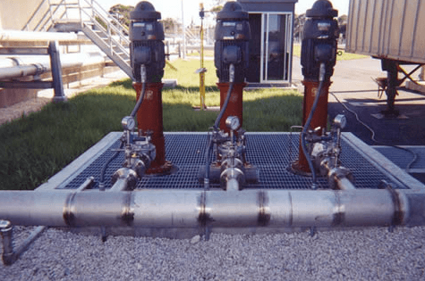
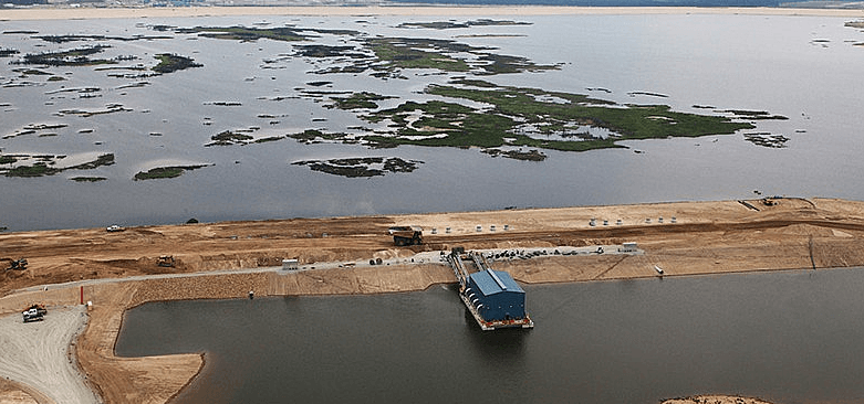
Reclaim water is pumped from the tailings pond by the reclaim barge pump station. Approximately halfway between the barge and the reclaim tank there is an inline booster pump station, which provides the necessary head to pump to the reclaim water tank.
The pumps are controlled by level switches in the reclaim tank. The barge pumps are turned on first and when the suction side of the booster pumps becomes pressurized, the booster pumps are turned on. On shut down, a signal from the reclaim tank turns off the booster pumps. After they have turned off, the barge pumps are turned off.
The pipes are insulated but not heat traced, so they are automatically drained back to the tailings pond after the pumps have been shut off for 1-1/2 hours, and the temperature is below freezing.
From the reclaim tank, water flows by gravity to the plant. This pipe is insulated and heat traced. The tank also receives overflow water from the plant fresh water tank.
There are flow meters at the barge and the reclaim tank to provide leak detection.
Detailed Process Description and Control
Preparation for Start up
- Ensure the barge is properly floating in the pond. Periodically, as the tailings level rises, the barge will have to be moved and the tailings pipe re-aligned. Ensure there are no low points in the hoses at the barge bridge.
- Walk the reclaim line to check for damage to the pipe or overhead wires. Open the sluice gate at the tailings spillage diversion.
- Ensure the leak detection system components and alarms are operational.
- Ensure the reclaim tank level switches and alarms are operational.
- Ensure the PLC is operational.
- Ensure the system pressure and temperature switches at the barge; and at the booster pump house are operational.
- Ensure all air/vacuum release valves, pressure relief valves and pressure gauges are operational, and their isolating valves open.
- Ensure all pump control valves are operational.
- Ensure all pump and pipeline isolating valves are open.
- Ensure both drain valves are closed.
- Ensure the barge heat tracing system is operational.
- Do not start any barge or booster pump unless the entire system is ready to operate.
Reclaim Barge Pump Station – start up
The 60 HP reclaim pond pumps are controlled by the high and low level switches in the reclaim tank, the pump control valves and the hand switches. Under normal conditions only one of the two reclaim pond pumps operate at a time, therefore the operation of each pump system is identical.
 The pumps are started when the low level switch indicates low water level in the reclaim tank. One pump operates while one is on standby; they are alternated when the pump Hand/Off/Auto handswitches are on AUTO. When low level switch indicates a low water level in the reclaim tank and limit switch indicates that the pump control valve is closed, and the Hand/Off/Auto switch is on AUTO, the reclaim pond pump will start.
The signal from the low level switch also closes the drain valve, and the booster pump-house drain valve if they are not already closed. These valves close on the high speed setting. The signal which starts the reclaim pond pump also opens the pump control valve. Normally the valve opens on one speed. This throttles the pump to prevent it from “running away” against an empty pipe.
When the pipe downstream of the check valve is full (indicated by the high pressure switch), the slow cycle is skipped. This reduces valve wear due to high velocity through the valve.
The pressure relief valve opens automatically on a high pressure surge to prevent water hammer damage. It must always be connected, and the isolating valve open, when there is water in the system.
Reclaim Booster Pump Station Start up
The reclaim booster pumps are controlled by the high and low level switches in the reclaim tank, the booster pump control valves, the high and low pressure switches, and the hand switches. Under normal conditions only one of the two booster pumps operate at a time. Therefore, the operation of each pump system is identical.
The booster pumps are started when the high pressure switch indicates pressure at the pump suction, and when the low level switch indicates low water level in the reclaim tank. After the start signal, the operation of the booster pumps, the pump control valves, the limit switch, the high pressure switch, and the Hand/Off/Auto switch is identical to the operation of the equivalent components in the tailings pond barge. The signal from the low level switch will close the drain valve and prevent water from the reclaim pond from bypassing the booster pumps.
If there is loss of pressure on the suction of the booster pumps, which would cause cavitation and damage the pumps, the low pressure switch (PSL-809) shuts down the operating pump.
The pressure relief valve will open automatically on a high pressure surge to prevent water hammer damage. The pressure relief valve must always be connected, and the isolating valve open, when there is water in the system.
Reclaim Booster Pump station Shut down
The pumps are stopped by the high level switch indicating high water level in the reclaim tank. The high level signal causes the pump control valve to close on two speeds (first fast, then slow). When the limit switch indicates that the valve is fully closed, the booster pump is shut off.
When both booster pumps are off, the valve Hand/Off/Auto hand switch is on AUTO, and there is a signal from the low temperature switch, the drain valve will open. The low temperature switch is located on the reclaim barge.
Reclaim Barge Pump Station Shut down
The barge pumps are stopped when both reclaim booster pumps are off, and the high level switch indicates high water level in the reclaim tank. On a shut down, the operation of the pump control valve, the limit switch and the reclaim pond pumps is identical to the operation of the equivalent components in the booster pump station.
When both reclaim pond pumps are off, the temperature switch timer is started. When the temperature switch has been indicating freezing temperature for 1-1/2 hours and the valve Hand/Off/Auto hand switch is on AUTO, the drain valve is opened, and the pipeline is drained back into the pond. The low temperature signal also opens the drain valve in the booster pump station.
Reclaim Tank
The reclaim tank is equipped with high and low level switches which control the reclaim pond and booster pumps, and high and low level switches which trigger alarms in the mill control panel when the water levels are outside the normal operating range. There is also a locally mounted level indicator on the reclaim tank.
The tailings seepage pump is located at a low point on the tailings dam seepage interception trench. This pump is controlled by high and low level switches, when the Hand/Off/Auto hand switch is on AUTO.
Operation Start UP
1. Select booster pump hand switches for AUTO.
2. Select booster powerhouse drain hand switch for AUTO.
3. Select drain valve hand switch for AUTO.
4. Select barge pump hand switches for AUTO.
Shut down
1. Select booster pump hand switches for OFF.
2. Select barge pump hand switches for OFF.
3. Select booster powerhouse drain valve selector switch for HAND, and open valve.
4. Select drain valve selector switch for HAND, and open valve.
To ensure that there is no leakage in the reclaim water system, the system is equipped with two leak detection circuits. The first circuit will alarm a pipeline leak if either reclaim pond pump is running and the magnetic flowmeter’s signal to the low flow switch indicates a low flowrate in the pipeline to the reclaim booster pumps. If either reclaim pond pump is running and there is a low flow indication, a low flow alarm will sound at the mill control panel. The second system will alarm a pipeline leak if the flow downstream from the booster pump station, measured with the magnetic flowmeter, is different than the flow into the reclaim tank, measured by the magnetic flowmeter. The signals from both magnetic flowmeters are compared, and if the signals are different, a differential flow alarm will sound at the mill control panel.
Use the following procedure in case of a pipeline leak:
1. Close the sluice gate at the tailings spillage diversion.
2. Follow normal shutdown procedure.
3. Ensure all spilled reclaim water is diverted into the tailings pond prior to repairing damage and re-starting.
https://www.911metallurgist.com/plant-tailings-reclaim-water-system
https://www.911metallurgist.com/diesel-power-generation-distribution-for-mining-operations
