In previous topics, we have seen that discontinuities constitutes as a weakness in the rock mass. In fact, failure of a slope, for example, is often triggered by the failure of discontinuities in triggering block instability. These can occur on natural or man-made slopes.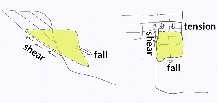
This figure illustrates two possible failure scenarios involving failure of discontinuities. On the left, failure occurs along one discontinuity whose shear stress had been exceeded. On the two right, two discontinuities have failed, one in shear, one in tension. Such a mechanism has occurred on this photo. You can see that the rock is yellow or grey. Grey reflects exposition to water, while the yellow colour pertains to fresh rock that has not been exposed to water. The yellow zone outlines the volume that has fallen.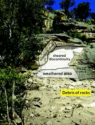
The fail face are yellow suggesting that water pressure is not the cause of instability instead it is suggested that some weathering has weakened the base resulting in large block almost hanging from the top with some stress contribution from the back and one side. At some point, the tensile and shear strengths were exceeded and the whole block fell. Note that the back and to faces are very smooth. They correspond to existing discontinuities. In contrast, the left side is very rough suggesting that failure did not occur along the discontinuity, but through the rock mass. The issue of failing blocks can also rise underground.
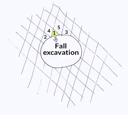
Consider, for example, the case of this secular excavation in a fractured rock mass having two discontinuity sets. The orientation of the discontinuities is favourable to the fall of the block highlighted in yellow and following its fall it is likely that the blocks around it, number four and five will also move possibly releasing blocks two and three. In some cases the modification of the stress state plays a role in the instability mechanism. Look at this example. A rectangular opening is created in a fractured rock mass with vertical and horizontal discontinuities. Six blocks, number one to six could possibly fall if it were not for the confining effect of the horizontal stress. This is like holding books together in this manner. If we apply a confining effect, we can hold all the books. If you release the confinement, the books fall. This happens underground if the horizontal pressure drops, which can occur if the pillar progressively deforms. 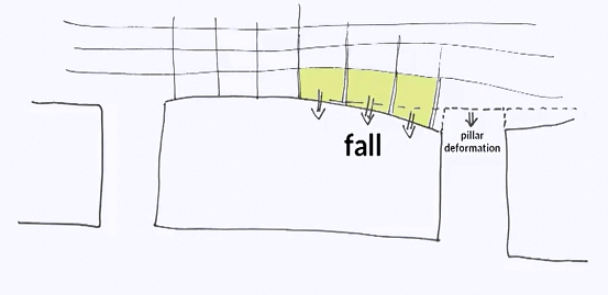 As a result, the joints have opened and confining the blocks highlighted in yellow and releasing them in a similar manner to what happened with the books. So the blocks are initially stable, but can fall after some time and all the blocks across a span could possibly fall. Block instabilities can to some extent be avoided or mitigated. For example, a rock engineering project can be developed within an awareness of the rock discontinuity orientation in order to limit the possibility to create unstable blocks.
See for example this figure where the slopes have been cut parallel to the joint orientation. This eliminated the risk of a sliding block. However it may lead to very flat slopes which is not always possible due to space constraint. It can also lead to very steep slopes where other types of instabilities not covered in this module can be triggered. Then mitigation measures are possible, among which active solutions where the clocks are prevented from detaching form a slope or passive measures where block can detach but the fall is controlled and the blocks are stopped before any damaging impact the choice of measures, active or passive can be limited for certain applications typically underground. 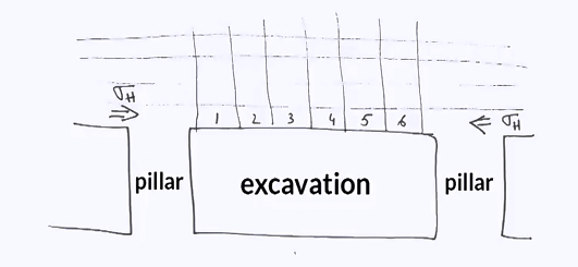 Here you can see a sketch of active protection consisting of rock bowls placed in the slope and holding the blocks together preventing the fall. Rock bowls are typically used with the mesh as per this figure where the bolts and mesh are used to stabilises a roof. Passive solutions are more common on slopes where blocks can detach and fall but be stopped at the bottom of the slope by properly engineered barrier. Examples of these type of barriers will be given in module three.
These examples highlight the fact that discontinuity orientation is crucial when it comes to rock engineering projects. 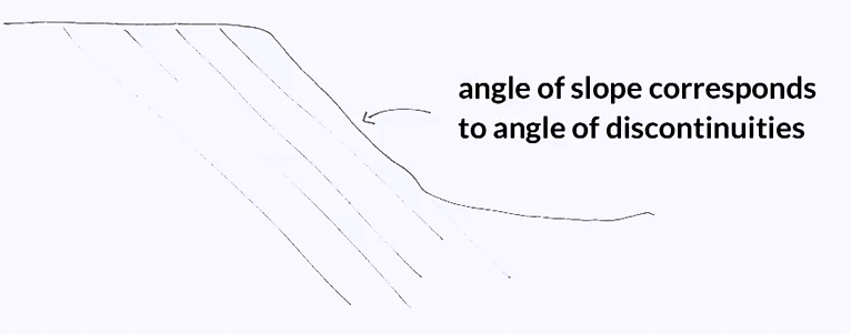 A large proportion of block instabilities can be predicted and avoided if the discontinuity orientation are properly surveyed and are counted for.
https://youtu.be/2_z9-xOj3P4
