AG and SAG mills are now the primary unit operation for the majority of large grinding circuits, and form the basis for a variety of circuit configurations. SAG circuits are common in the industry based on:
- High single-line capacities (leading to capital efficiency)
- The ability to mill a broad range of ore types in various circuit configurations, with reduced numbers of unit operations (and a corresponding reduction in the complexity of maintenance planning and coordination)
- Favourable operating costs (with contributions from reduced liner/media consumption relative to conventional circuits)
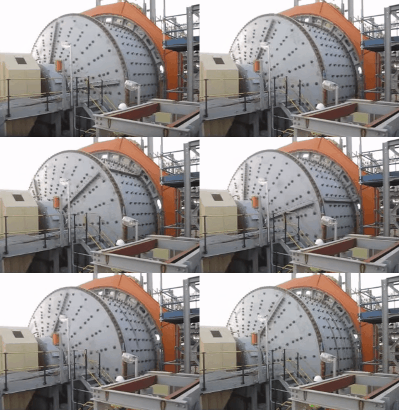
Though some trepidation concerning AG or SAG circuits accompanied design studies for some lime, such circuits are now well understood, and there is a substantial body of knowledge on circuit design as well as abundant information that can be used for bench-marking of similar plants in similar applications. Because SAG mills rely both on the ore itself as grinding media (to varying degrees) and on ore-dependent unit power requirements for milling to the transfer size, throughput in SAG circuits are variable. Relative to other comminution machines in the primary role. SAG mill operation is more dynamic, and typically requires a higher degree of process control sophistication. Though more complex in AG/ SAG circuits relative to the crushing plants they have largely replaced, these issues are well understood in contemporary applications.
AG/SAG mills grind ore through impact breakage, attrition breakage, and abrasion of the ore serving as media. Autogenous circuits require an ore of suitable competency (or fractions within the ore of suitable competency) to serve as media. SAG circuits may employ low to relatively high ball charges (ranging from 2% to 22%, expressed as volumetric mill filling) to augment autogenous media. Higher ball charges shift the breakage mode away from attrition and abrasion breakage toward impact breakage; as a result, AG milling produces a finer grind than SAG milling for a given ore and otherwise equal operating conditions. The following circuits are common in the gold industry:
- Single stage AG/SAG milling
- AG/SAG mills as a primary grinding stage in a circuit with or without additional stages of comminution
- Inclusion of pebble-crushing circuits in the AG/SAG circuit
- Circuits above, but with feed preparation including two stages of crushing—typically referenced as pre-crushing
Common convention generally refers to high-aspect ratio mills as SAG mills (with diameter to effective grinding length ratios of 3:1 to 1:1), low-aspect ratio mills (generally, a mill with a significantly longer length than diameter) are also worth noting. Such mills are common in South African operations; mills are sometimes referred to as tube mills or ROM ball mills and are also operated both autogenously and semi-autogenously. Many of these mills operate at higher mill speeds (nominally 90% of critical speed) and often use “grid” liners to form an autogenous liner surface. These mills typically grind ROM ore in a single stage. A large example of such a mill was converted from a single-stage milling application to a semi autogenous ball-mill-crushing (SABC) circuit, and the application is well described. This refers to high-aspect AG/SAG mills.
Ball Charge Motion inside a SAG Mill
With a higher density mill charge. SAG mills have a higher installed power density for a given plant footprint relative to AC mills. With the combination of finer grind and a lower installed power density (based on the lower density of the mill charge), a typical AG mill has a lower throughput, a lower power draw, and produces a finer grind. These factors often translate to a higher unit power input (kWh/t) than an SAG circuit milling the same ore. but at a higher power efficiency (often assessed by the operating work index OWi, which if used most objectively, should be corrected by one of a number of techniques for varying amounts of fines between the two milling operations).
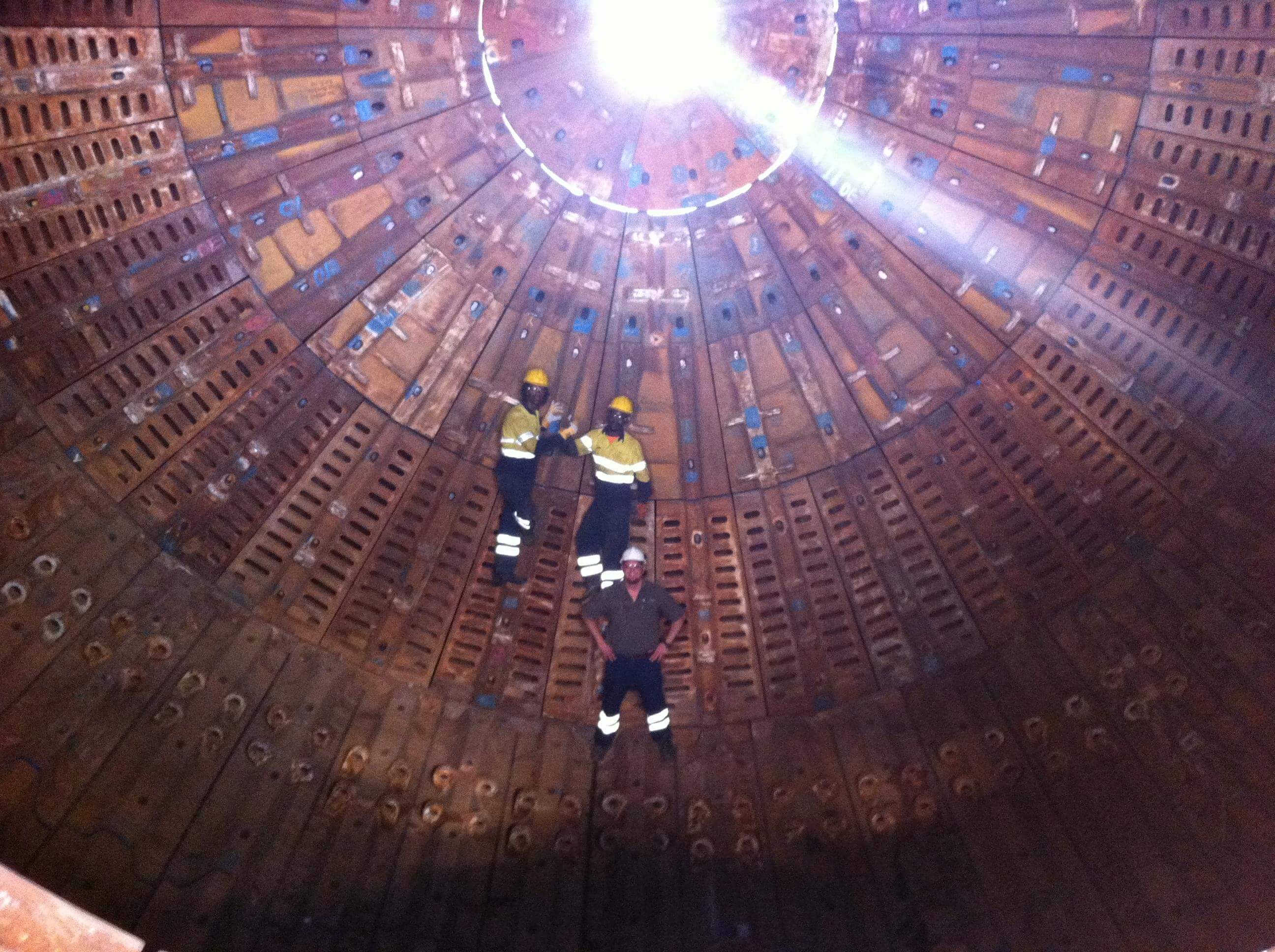
In the presence of suitable ore, an autogenous circuit can provide substantial operating cost savings due to a reduction in grinding media expenditure and liner wear. In broad terms, this makes SAG mills less expensive to build (in terms of unit capital cost per ton of throughput) than AG mills but more expensive to operate (as a result of increased grinding media and liner costs, and in many cases, lower power efficiency). SAG circuits are less susceptible to substantial fluctuations due to feed variation than AG mills and are more stable to operate. AG circuits are more frequently (but not exclusively) installed in circuits with high ore densities. A small steel charge addition to an AG mill can boost throughput, result in more stable operations, typically at the consequence of a coarser grind and higher operating costs. An AG circuit is often designed to accommodate a degree of steel media for circuit flexibility. AG mills (or SAG mills with low ball charges) are often used in single-stage grinding applications.
Based on their higher throughput and coarser grind relative to AG mills, it is more common for SAG mills to he used as the primary stage of grinding, followed by a second stage of milling. AG/SAG circuits producing a fine grind (particularly single-stage grinding applications) are often closed with hydrocyclones. Circuits producing a coarser grinds often classify mill discharge with screens. For circuits classifying mill discharge at a coarse size (coarser than approximately 10 mm), trommels can also be considered to classify mill discharge. Trommels are less favorable in applications requiring high classification efficiencies and can be constrained by available surface area for high-throughput mills. Regardless of classification equipment (hydrocyclone, screen, or trommel), oversize can be returned to the mill, or directed to a separate stage of comminution.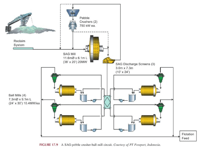
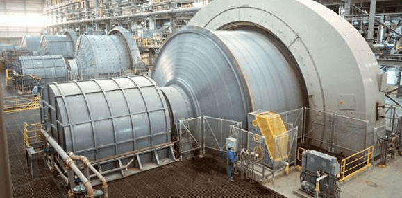
Many large mills around the world (Esperanza with a 12.8 m mill. Cadia and Collahuasi with 12.2-m mills, and Antamina. Escondida # IV. PT Freeport Indonesia, and others with 11.6-m mills) have installed SAG mills of 20 MW. Gearless drives (wrap-around motors) are typically used for large mills, with mills of 25 MW or larger having been designed. Several circuits have single-line design capacities exceeding 100,000 TPD. A large SAG installation (with pebble crusher product combining with SAG discharge and feeding screens) is depicted here below, with the corresponding process flowsheet presented in Figure 17.9.
Adding pebble crushing as a unit operation is the most common variant to closed-circuit AG/SAG milling (instead of direct recycle of oversize material ). The efficiency benefits (both in terms of grinding efficiency and in capital efficiency through incremental throughput) are well recognized. Pebble crushers are effective at reducing the buildup of critical-sized material in the mill load. Critical-sized particles are those where the product of the mill feed-size distribution and the mill breakage rates result in a buildup of a size range of material in the mill load, the accumulation of which limits the ability of the mill to accept new feed. While critical-size could be of any dimension, it is most typically synonymous with pebble-crusher feed, with a size range of 13—75 mm. Critical-sized particles can result from a simple failure of a mill’s breakage rates to exceed the breakage rate of incoming particles, and particles generated when breaking larger particles. Alternatively, a second type of buildup of critical-sized material can result due to a combination of rock types in the feed that have differing breakage properties. In this case, the harder fraction of the mill feed builds up in the mill load, again restricting throughput. Examples of materials in this category include diorites, chert, and andesite. When buildup of these materials does occur, pebble crushing can improve mill throughput even more dramatically than when the critically sized fraction results purely from a breakage rate deficit alone. For these ore types, a pebble-crushing circuit is tin imperative for efficient circuit operation.
Currently, every AG/SAG flowsheet evaluation is likely to consider the inclusion of a pebble crusher circuit. Flowsheets that do not elect to include pebble crushing at construction and commissioning may include provisions for future retrofitting a pebble-crushing circuit. Important aspects of pebble crusher circuit design include:
- Preparation of a clean, well-sized, and dry feed;
- Metal removal (with additional protection via metal detectors and bypass);
- Surge capacity (by using bins, or alternately and more costly, a pebble stockpile);
- Sufficient capacity (primarily a concern of large circuits where multiple pebble crushers are required to serve one grinding line);
- Design for by-passing crushers during maintenance, and
- Evaluation of the where to reintroduce the crushed pebbles back to the grinding circuit.

SAG mill by feeding crushed pebbles
The standard destination for crushed pebbles has been to return them to SAG feed. However, open circuiting the SAG mill by feeding crushed pebbles directly to a ball-mill circuit is often considered as a technique to increase SAG throughput. An option to do both can allow balancing the primary and secondary milling sections by having the ability to return crushed pebbles to SAG feed as per a conventional flowsheet, or to the SAG discharge. Such a circuit is depicted here on the right. By combining with SAG discharge and screening on the SAG discharge screens, top size control to the ball-mill circuit feed is maintained while still unloading the SAG circuit (Mosher et al, 2006). A variant of this method is to direct pebble-crushing circuit product to the ball-mill sump for secondary milling: while convenient, this has the disadvantage of not controlling the top size of feed to the ball-mill circuit. There have also been pioneer installations that have installed HPGRs as a second stage of pebble crushing.
The unit power requirement for SAG milling (both individually and as a fraction of the total circuit power) is worthy of comment. It can be very difficult operationally to trade grind for throughput in an SAG circuit—once designed and constructed for a given circuit configuration, an SAG mill circuit has limited flexibility to deliver varying product sizes, and a relatively fixed unit power input for a given ore type is typically required in the SAG mill. This is particularly true for those SAG circuits designed with a coarse closing size. As a result, under-sizing an SAG mill has disastrous results on throughput— across the industry, there are numerous examples of the SAG mill emerging as the circuit bottleneck. On the other hand, over-sizing an SAG circuit can be a poor utilization of capital (or an opportunity for future expansion!).
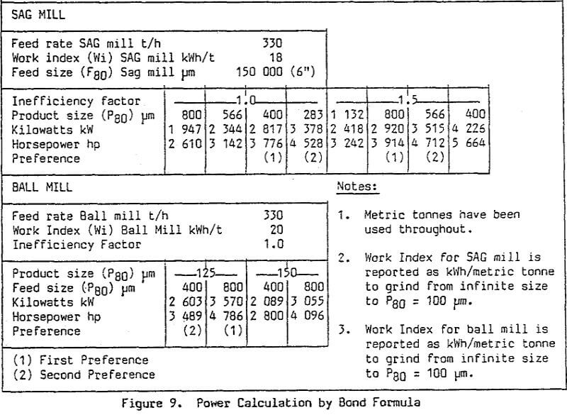
Traditionally, many engineers approached SAG circuit design as a division of the total power between the SAG circuit and ball-mill circuit, often at an arbitrary power split. If done without due consideration to ore characteristics, benchmarks against comparable operating circuits, and other aspects of detailed design (including steady-state tests, simulation, and experience), an arbitrary power split between circuits ignores the critical decision of determining the required unit power in SAG milling. As such, it exposes the circuit to risk in terms of failing to meet throughput targets if insufficient SAG power is installed. Rather than design the SAG circuit with an arbitrary fraction of total circuit power, it is more useful to base the required SAG mill size on the product of the unit power requirement for the ore and the desired throughput. Subsequently, the size of the secondary milling circuit is then sized based on the amount of finish grinding for the SAG circuit product that is required. Restated, the designed SAG mill size and operating conditions typically control circuit throughput, while the ball-mill circuit installed power controls the final grind size.
Aside from parameters fixed at design (mill dimensions, installed power, and circuit type), the major variables affecting AG/SAG mill circuit performance (throughput and grind attained) include:
- Feed characteristics in terms of ore hardness/competency
- Feed size distribution
- Selection of circuit configuration in terms of liner and grate selection and closing size (screen apertures or hydrocyclone operating conditions)
- Ball charge (fraction of volumetric loading and ball size)
- Mill operating conditions including mill speed (for circuits with variable-speed drives), density, and total mill load
The effect of feed hardness is the most significant driver for AG/SAG performance: with variations in ore hardness come variations in circuit throughput. The effect of feed size is marked, with both larger and finer feed sizes having a significant effect on throughput. With SAG mills, the response is typically that for coarser ores, throughput declines, and vice versa. However, for AG mills, there are number of case histories where mills failed to consistently meet throughput targets due to a lack of coarse media. Compounding the challenge of feed size is the fact that for many ores, the overall coarseness of the primary crusher product is correlated to feed hardness. Larger, more competent material consumes mill volume and limits throughput.
A number of operations have implemented a secondary crushing circuit prior to the SAG circuit for further comminution of primary crusher product. Such a circuit can counteract the effects of harder ore. coarser ore. decrease the size of SAG mill required, or rectify poor throughput due to an undersized SAG circuit. Notably, harder ore often presents itself to the SAG circuit as coarser than softer ore—less comminution is produced in blasting and primary crushing, and therefore the impact on SAG throughput is compounded.
Circuits that have used or do use secondary crushing/SAG pre-crush include Troilus (Canada), Kidston (Australia), Ray (USA), Porgera (PNG). Granny Smith (Australia), Geita Gold (Tanzania), St Ives (Australia), and KCGM (Australia). Occasionally, secondary crushing is included in the original design but is often added as an additional circuit to account for harder ore (either harder than planned or becoming harder as the deposit is developed) or as a capital-efficient mechanism to boost throughput in an existing circuit. Such a flowsheet is not without its drawbacks. Not surprisingly, some of the advantages of SAG milling are reduced in terms of increased liner wear and increased maintenance costs. Also, pre-crush can lead to an increase in mid-sized material, overloading of pebble circuits, and challenges in controlling recycle loads. In certain circuits, the loss of top-size material can lead to decreased throughput. It is now widespread enough to be a standard circuit variant and is often considered as an option in trade-off studies. At the other end of the spectrum is the concept of feeding AG mills with as coarse a primary crusher product as possible.
The overall circuit configuration can guide selection of die classification method of primary circuit product. Screening is more successful than trommel classification for circuits with pebble crushing, particularly for those with larger mills. Single-stage AG/SAG circuits are most often closed with hydrocyclones.
SAG Mill vs Ball Mill
|
|
|
To a more significant degree than in other comminution devices, liner design and configuration can have a substantial effect on mill performance. In general terms, lifter spacing and angle, grate open area and aperture size, and pulp lifter design and capacity must be considered. Each of these topics has had a considerable amount of research, and numerous case studies of evolutionary liner design have been published. Based on experience, mill-liner designs have moved toward more open-shell lifter spacing, increased pulp lifter volumetric capacity, and a grate design to facilitate maximizing both pebble-crushing circuit utilization and SAG mill capacity. As a guideline, mill throughput is maximized with shell lifters between ratios of 2.5:1 and 5.0:1. This ratio range is stated without reference to face angle; in general terms, and at equivalent spacing-to-height ratios, lifters with greater face-angle relief will have less packing problems when new, but experience higher wear rates than those with a steeper face angle. Pulp-lifter design can be a significant consideration for SAG mills, particularly for large mills. As mill sizes increases, the required volumetric capacity of the pulp lifters grows proportionally to mill volume. Since AG/SAG mill volume is roughly proportional to the mill radius cubed (at typical mill lengths) while the available cross-sectional area grow’s only as the radius squared, pulp lifters must become more efficient at transferring slurry in larger mills. Mills with pebble-crushing circuits will require grates with larger apertures to feed the circuit.
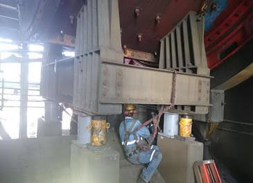
No discussion of SAG milling would be complete without mention of refining. Unlike a concentrator with multiple grinding lines, conducting SAG mill maintenance shuts down an entire concentrator, so there is a tremendous focus on minimizing required maintenance time; the reline timeline often represents the critical path of a shutdown (but typically does not dominate a shutdown in terms of total maintenance effort).
Reline times are a function of the number of pieces to be changed and the time required per piece. Advances in casting and development of progressively larger lining machines have allowed larger and larger individual liner pieces.
While improvements in this area will continue, the physical size limit of the feed trunnion and the ability to maneuver parts are increasingly limiting factors, particularly in large mills. The other portion of the equation for reline times is time per piece, and performance in this area is a function of planning, training/skill level, and equipment.
SAG Mill Liner Design
In summary:
A broad range of AG/SAG circuit configurations are in operation. Very large line plants have been designed, constructed, and operated. The circuits have demonstrated reliability, high overall availabilities, streamlined maintenance shutdowns, and efficient operation. AG/SAG circuits can handle a broad range of feed sizes, as well as sticky, clayey ores (which challenge other circuit configurations). Relative to crushing plants, wear media use is reduced, and plants run at higher availabilities. Circuits, however, are more sensitive to variations in circuit feed characteristics of hardness and size distribution; unlike crushing plants for which throughput is largely volumetrically controlled. AG/SAG throughput is defined by the unit power required to grind the ore to the closing size attained in the circuit. Very hard ores can severely constrain AG/SAG mill throughput. In such cases, the circuits can become capital inefficient (in terms of the size and number of primary milling units required) and can require more total power input relative to alternative comminution flowsheets. A higher degree of operator skill is typically required of AG/SAG circuit operation, and more advanced process control is required to maintain steady-state operation, with different operator/advanced process control regimens required based on different ore types.
SAG Mill Circuit Sampling
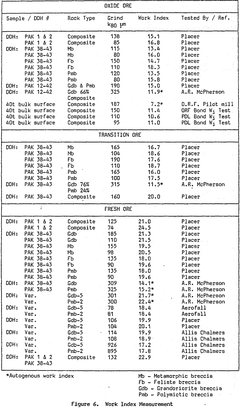
Many mills have been built based on data from inadequate sampling or from insufficient tests. With the cost of many mills exceeding several hundred million dollars, it is mandatory that geologists, mining engineers and metallurgists work together to prepare representative samples for testing. Simple repeatable work index tests are usually sufficient for rod mill and ball mill tests but pilot plant tests on 50-100 tons of ore are frequently necessary for autogenous or semiautogenous mills.
Preparation and selection of the test sample is of utmost importance. Procedures for autogenous and semiautogenous mill pilot plant tests are relatively simple for those experienced in running them. Reliable and repeatable results can be obtained if simple fundamental procedures are followed.
SAG Mill Operation
In order to initiate the design of any mill, including. autogenous and semi-autogenous types, the operating conditions must be defined. This includes the basic parameters of:
A. Mill Charge
- Charge Weight/Volume/Percent Filling.
- Ore Specific Gravity.
- Percent Rock or Ore Charge.
- Percent Ball Charge (if semi-autogenous).
- Percent Solids – in the mill.
B. Mill Power
- Mill Speed: Percent Critical/Peripheral
- Direction of Rotation
- Power Draft.
- Design Drive Power.
C. Total Feed Conditions, including total mill volumetric flow rate; recirculating load.
- Feed Chute Design.
- Discharge Diaphram Design.
- Component Design.
- Trommel or Vibrating Screen Considerations.
D. Milling Circuit Flow Sheet.
- Types of Classifiers – Trommels, Vibrating Screens – Cyclones.
- Mill Control Schemes
Semi Autogenous Design Factors
The design of large mills has become increasingly more complicated as the size has increased and there is little doubt that without sophisticated design procedures such as the use of the Finite Element method the required factors of safety would make large mills prohibitively expensive.
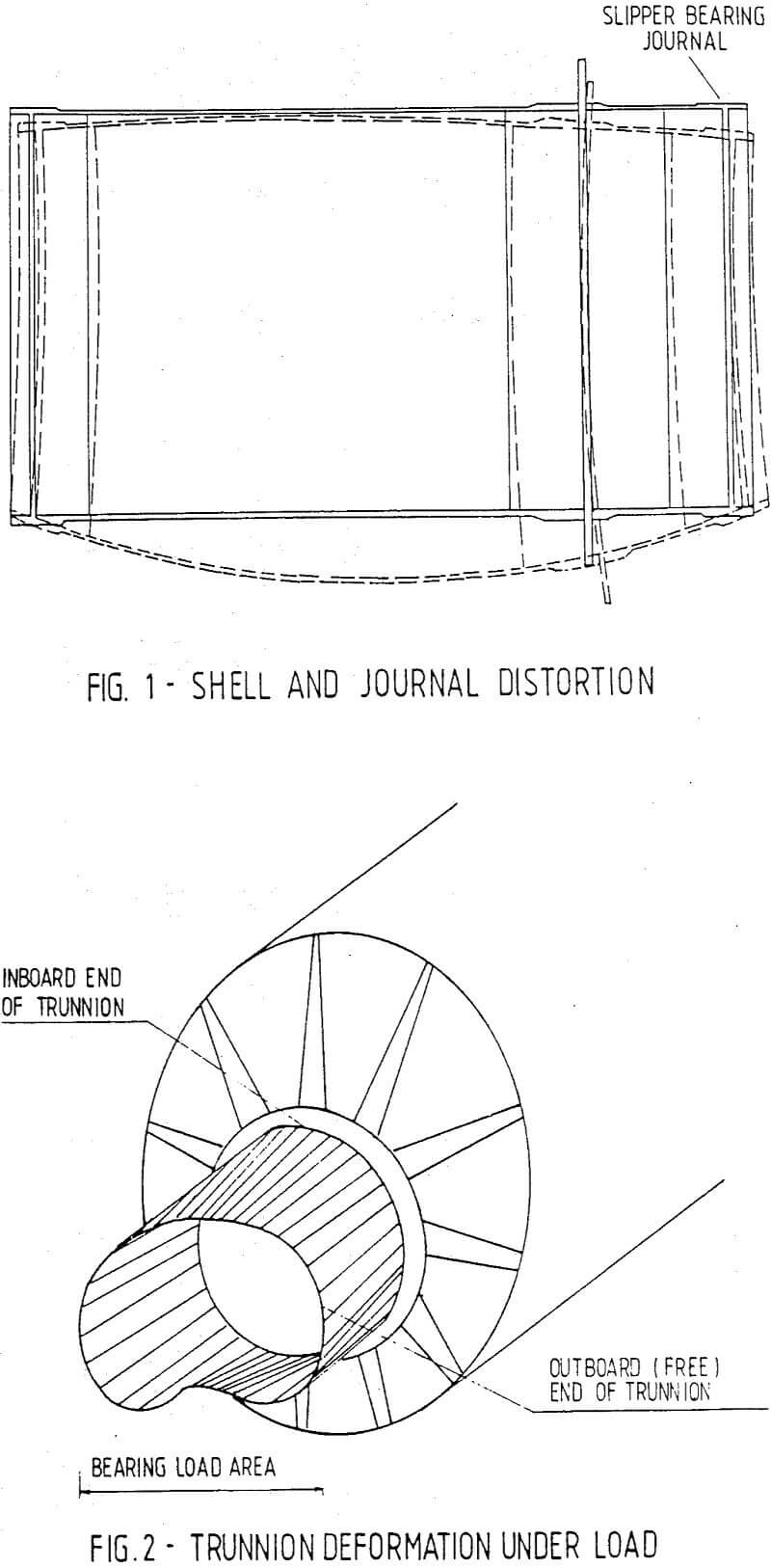
In the past the design of small mills, up to +/- 2,5 metres diameter, was carried out using empirical formulae with relatively large factors of safety. As the diameter and length of mills increased several critical problem areas were identified. One of the most important was the severe stressing which took place at the connection of the mill shell and the trunnion bearing end plates, which is further aggravated by the considerable distortion of the shell and the bearing journals due to the dynamic load effect of the rotating mill with a heavy mass of ore and pulp being lifted and dropped as the grinding process took place. Incidentally the design calculation of the deformations of journal and mill shell is based on static conditions, the influence of the rotating mass being of less importance. An indication of shell and journal distortion is shown in Figure 1.
Investigations carried out by Polysius/Aerofall revealed that practical manufacturing considerations dictated some aspects of trunnion end design. Whereas the thickness of the trunnion in the case of small diameter mills was dictated by foundry practice which required a minimum thickness of metal the opposite was the case in the design of large diameter mills where the emphasis was not to exceed a maximum thickness both from the mass/casting temperature point of view and the cost aspect.
While the deformation of shell and end plates was acceptable in the case of small mills due in some extent to the over stiff construction, the deformation in the large, more flexible, mills is relatively high. The ratio of the trunnion thickness to trunnion diameter in a mill of 2,134 m diameter is almost twice that of a mill of 5,8 m diameter, i.e. a ratio (T/D) of 0,116 to 0,069 for the large mill.
However the design stress levels at the trunnion/head transition in the case of the large mill are almost 250% of those in the small mill.
The use of large memory high speed computers coupled with finite element methods provides the means of performing stress calculations with a high degree of accuracy even for the complex structures of large mills. The precision with which the stress values can be predicted makes the use of safety factors based on empirical formulae generally unnecessary.
In the case of large diameter trunnion bearing mills the distortion which takes place is further compounded by the fact that the deformation varies across the width of the bearing journal due to the fact that the end of the journal attached to the mill end plate is less liable to distortion than the outlet free end of the journal. This raises serious complications as far as the development of the hydrodynamic fluid oil film of the bearing is concerned since the minimum oil gap may be only 0,05 mm.
An exaggerated indication of trunnion deformation is shown in Figure 2.
Obviously a thinner oil film is adequate where the deformation of the journal is less while at the unsecured end of the journal widely varying oil film thickness is necessary to maintain the correct oil pressure to support the mill. A solution to this problem has been the advent of the hydrostatic bearing with a supply of high pressure oil pumped continuously into the bearings.
Incorporating the mill bearing journals as part of the mill shell reduced the magnitude of the problem of distortion although there is always out of round deformation of the shell. The variation across the width of the journal surface is less pronounced than is the case with the trunnion bearing.
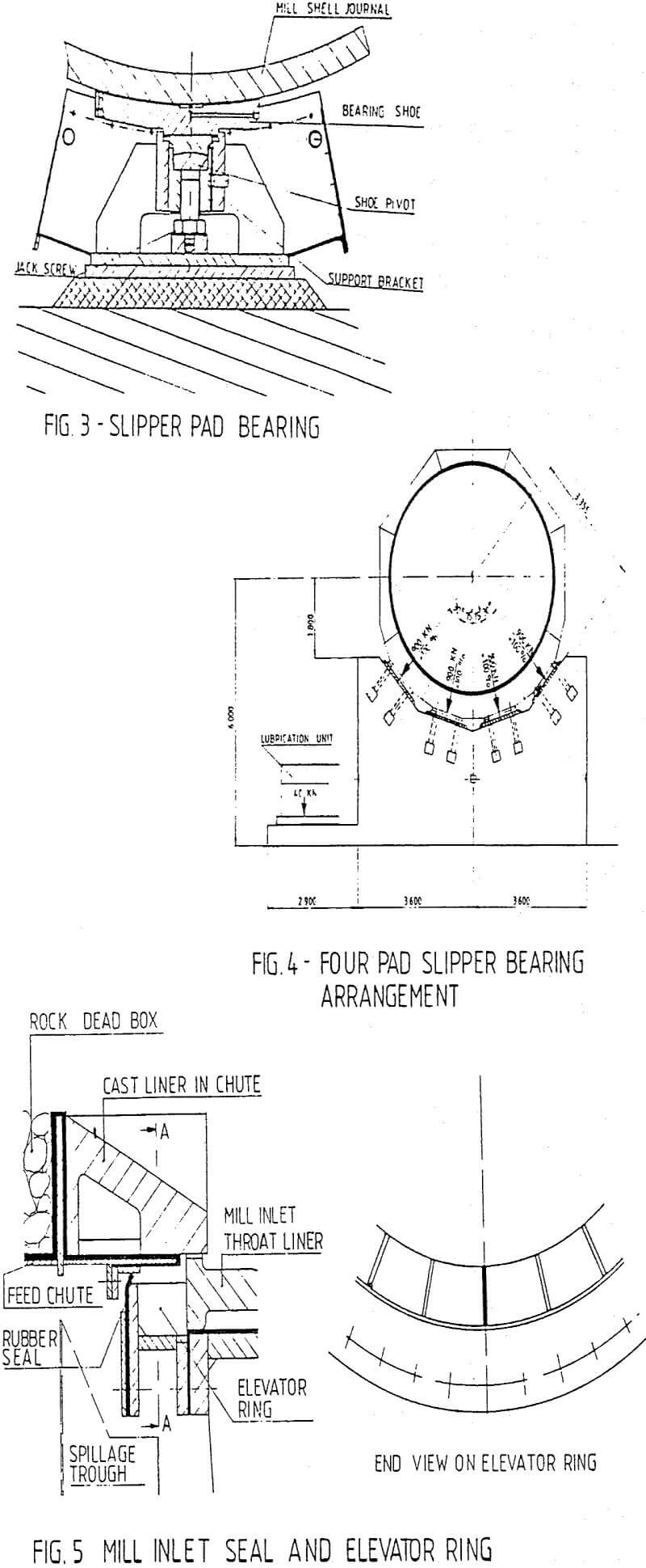
The replacement of a single bearing with a number of individual self adjusting bearing pads which together support the mill has lessened the undesirable effects of deformation while improving the efficiency of the bearing.
The ability of each individual bearing-pad to adjust automatically to a more localised area of the shell journal gives rise to improved contact of the oil film with both the bearing surface and the journal and in the case of hydrodynamic oil systems makes it unnecessary to supply oil at constant high pressure once the oil film has been established. A cross-section of a slipper pad bearing is shown in Figure 3.
 |
 |

SAG Mill Operation Example
Kidston Gold Mines is a 14 000 tonnes per day rated operation located 280 kilometers west of Townsvilie in Queensland. The principle shareholder is Placer Development Limited.
Kidston’s orebody consists of 44.2 million tonnes graded at 1.79 g/t gold and 2.22 g/t silver. Production commenced in January, 1985, and despite a number of control, mechanical and electrical problems, each month has seen a steady improvement in plant performance to a current level of over ninety percent rated capacity.
Process Plant Description
The cyanidation plant consists of a primary crushing plant, a semi-autogenous grinding circuit, agitation leaching circuit, cyclone wash circuit, gold recovery circuit and carbon regeneration circuit.
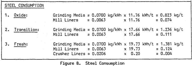
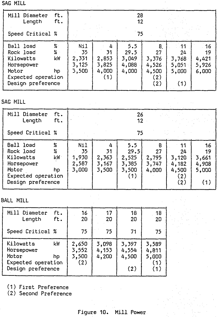
The grinding circuit comprises one 8530 mm diameter x 3650 mm semi-autogenous mill driven by a 3954 kW variable speed dc motor, and one 5030 mm diameter x 8340 mm secondary ball mill driven by a 3730 kW synchronous motor. Four 1067 x 2400 mm vibrating feeders under the coarse ore stockpile feed the SAG mill via a 1067 mm feed belt equipped with a belt scale. Feed rate was initially controlled by the SAG mill power draw with bearing pressure as override.
Integral with the grinding circuit is a 1500 cubic meter capacity agitated surge tank equipped with level sensors and variable speed pumps. This acts as a buffer between the grinding circuit and the flow rate sensitive cycloning and thickening sections.
SAG Mill Design and Specification
The Kidston plant was designed to process 7500 tpd fresh ore of average hardness; but to optimise profit during the first two years of operation when softer oxide ore will be treated, the process equipment was sized to handle a throughput of up to 14 000 tpd. Some of the equipment, therefore, will become standby units at the normal throughputs of 7 000 to 8 000 tpd, or additional milling capacity may be installed.
The SAG mill incorporates a design which allowed expedient manufacturing to high quality specifications, achieved by selecting a shell to head to trunnion configuration of solid elements bolted together. This eliminates difficult to fabricate and inspect areas such as a fabricated head welded to shell plate, fabricated ribbed heads, plate or casting welded to the head in the knuckle area and transition between the head and trunnion.
Motor torque at full load current is 214.4 kNm up to base speed (176 rpm) and 184.0 kNm from base to top speed. Maximum accelerating torque is 175 percent.
Operating Problems Since Commissioning
Considerable variation in ore hardness, the late commissioning of much of the instrumentation and an eagerness to maximise mill throughput led to frequent mill overloading during the first four months of operation. The natural operator over-reaction to overloads resulted numerous mill grindouts, about sixteen hours in total, which in turn were largely responsible for grate failure and severe liner peening. First evidence of grate failure occurred at 678 000 tonnes throughput, and at 850 000 tonnes, after three grates had been replaced on separate occasions, the remaining 25 were renewed. The cylinder liners were so badly peened at this stage that no liner edge could be discerned except under very close scrutiny and grate apertures had closed to 48 percent of their original open area.
The original SAG mill control loop, a mill motor power draw set point of 5200 Amperes controlling the coarse ore feeder speeds, was soon found to give excessive variation in the mill ore charge volume and somewhat less than optimal power draw.
The first major commissioning failure on the SAG mill occurred during installation when the mill was inched without adequate lubricant flow, resulting in the wiping of the feed end trunnion bearing.
The armature, weighing 19 tonnes, together with the top half magnet frame, were trucked two thousand kilometers to Brisbane for rewinding and repairs. The mill was turning again on January 24 after a total elapsed downtime of 14 days. After a twelve day stoppage due to a statewide power dispute in February, the mill settled down to a fairly normal operation, apart from some minor problems with alarm monitoring causing a few spurious trips. One cause of the mysterious stoppages was tracked down to the cubicle door interlocks which stuttered whenever the mining department fired a bigger than usual blast.
The open trunnion bearings are sealed with a rubber ring which proved ineffective in preventing ingress of water, and occasionally solids, from feed chute chokes and spillages. Contamination and emulsification of the oil with subsequent filter choking has been responsible for nearly eighteen percent of SAG mill circuit shutdowns. Despite the very high levels of contamination, no damage has been sustained by the bearings which has at least proved the effectiveness of the filters and other protection devices.
Design Changes and Future Operating Strategies
Design changes to date have, predictably, mostly concentrated on improving liner life and minimising discharge grate damage. Four discharge grates with thickened ends have performed satisfactorily and a Mk3 version with separate lifters and 20 mm apertures is currently being cast by Minneapolis Electric.
Cylinder liners will continue to be replaced with high profile lifters only on a complete reline basis. While there is the problem of reduced milling capacity with reduced lifter height towards the end of liner life, it is hoped to largely offset this by operating at higher mill speeds.
Mill feed chute liner life continues to be a problem. The original chrome-moly liners lasted some three months and a subsequent trial with 75 mm thick clamped Linhard (rubber) liners turned in a rather dismal life of three weeks.
