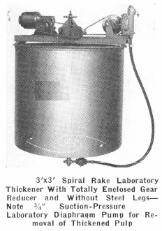
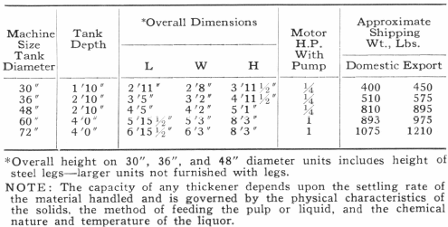
The Spiral Rake Laboratory Thickener, for continuous ore testing laboratories and ore dressing and industrial pilot plants, is built as a laboratory unit that embodies the same principles and produces the same results on a small scale as the commercial size Spiral Rake Thickener. Various diameters, from 3 feet up to commercial size units are available. Two convenient sizes for most applications are the 3 foot diameter by 3 foot depth and the 6 foot diameter by 3 foot depth.
The Spiral Rake Laboratory Thickener has the regular patented Spiral Rakes which convey the thickened pulp to the center cone in one revolution. Rakes are strongly braced angle iron and will easily withstand average overload conditions. Also, there is less chance of overloading due to the design of the patented Spiral Rakes accomplishing rapid removal of thickened pulp.
A ¾” Suction-Pressure Laboratory Diaphragm Pump is provided for removal of the thickened pulp. Pump is driven by thickener drive which consists of a totally enclosed gear reducer and gear-motor. Entire unit is self-contained, easily portable, and can be set up at any desired point in the plant.
Special shallow tray thickeners for handling extremely frothy materials can also be supplied. Let us make recommendations to suit your laboratory requirements.
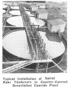
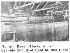
Rake Thickener is used to dewater pulps in many processes, either to reclaim the solution or to lower the moisture content of the solid constituent of the pulp. This unit is also extensively used in counter-current decantation systems such as applied to the cyanidation of gold and silver ores and other chemical processes.
Spiral Rake Thickeners are built in several types —the exact type depending upon the specific application. The use of patented Spiral Rakes is of special significance as it results in a structure of greater strength with the further advantage that the time required to move a particle from the periphery of the tank to the center is greatly reduced. This is important in that the quicker settled material is moved to the center discharge, the less trouble will be encountered due to overloads.
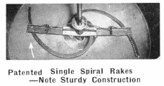
The rake assembly used in Spiral Rake Thickeners, up to and including the 20′ diameter, is usually a single spiral. As the thickener diameter increases, the rake assembly is modified to meet requirements. Essentially, the pattern followed is to use spiral rakes singly, then, as the diameter increases, to use a double spiral with auxiliary angle rakes near the periphery of the tank. The rake assembly is attached to the rake shaft through a steel spider. The advantage of steel over cast iron at this critical point is readily apparent.
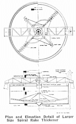
If, for some special reason, the use of an angle rake assembly is preferable, thickeners equipped with this type rake assembly are available.
The gear reducer unit of Spiral Rake Thickeners is totally enclosed in a cast gear-housing which incorporates a rake lifting device. This rake lifting mechanism may be either hand operated, with suitable gearing to allow easy hand operation, or motor driven. Automatic rake lifting devices are also available.
Low operating speeds required by the rake assembly are obtained through a worm gear reduction. The worm gear is of modern steel construction with cut teeth. The machine cut worm pinion which drives the gear is of special bronze.
The complete enclosure of the worm gear and pinion, which operate in a bath of oil within the gear housing, prevents the entrance of foreign material and oil leakage. Grease fittings are provided for the lubrication of the worm and rake shafts.
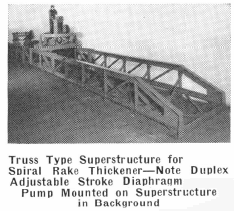
All Spiral Rake Thickeners are designed with a low-head type superstructure that meets exacting specifications. The superstructure can be supplied completely assembled or knocked down, as specified by the customer or dictated by transportation facilities, and it may be of either welded or bolted construction. If a Diaphragm Pump is to be used with the thickener, it is advisable to order beam extensions as in this way a mounting is provided for the pump and the cost is much less than providing mountings in the field.
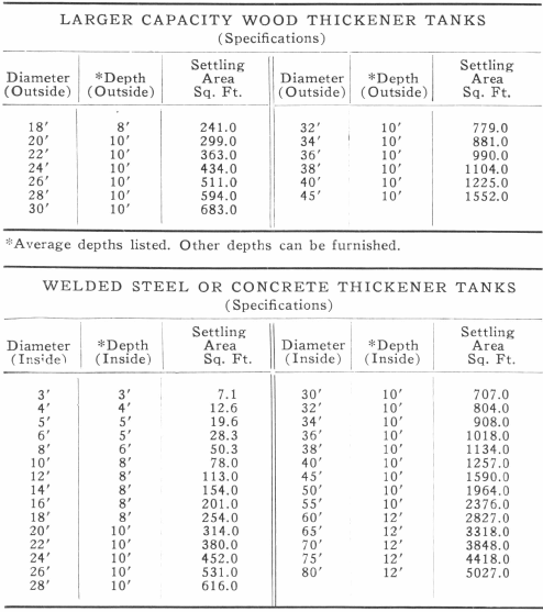
Tanks for Spiral Rake Thickeners may be wood, welded steel, bolted steel, or concrete. Equipment Company’s experienced engineering staff will gladly assist with the proper tank selection to meet specific requirements.
The center feed well is constructed of rolled steel plate and equipped with height adjustment rods so that an optimum setting can readily be obtained. Heavy rolled steel plate is also used in forming the discharge cone which has a rim with bolt holes for attaching it to the tank.
Type of drive required may be specified by the customer, such as belt drive from a lineshaft; gearmotor direct-connected with the worm shaft; V-belt drive from gearmotor; chain drive from gearmotor. or auxiliary jackshaft mounted on superstructure to drive from a high speed motor.
There are several types of overload alarms available. Although the equipping of thickeners with overload alarms is usually advisable, the use of patented Spiral Rakes has a very definite tendency to eliminate overload conditions due to the rapid removal of settled solids.
Since the capacity of a thickener depends upon the settling rate of the material to be handled, Equipment Company, which maintains a completely equipped metallurgical laboratory, will gladly determine these requirements and investigate the possibility of conditioning the pulp to improve its settling rate. Thickening tests are conducted free of charge to the customer. Let us conduct tests on the material you wish to thicken and make recommendations for the proper equipment to solve your thickening problem.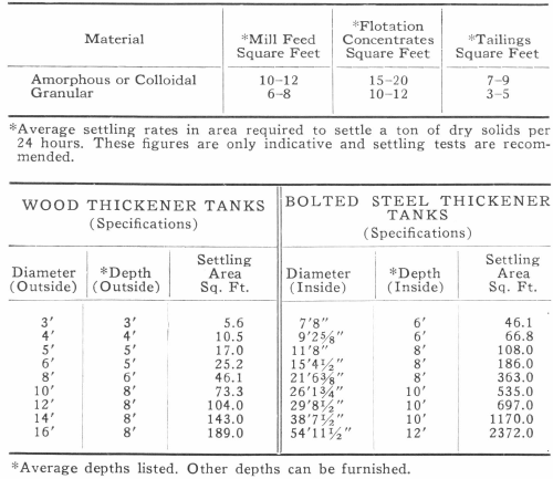
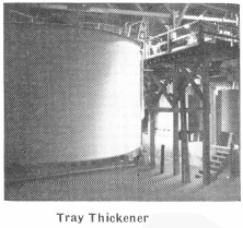
Thickener Tray
The Tray Thickener consists essentially of a super-structure and mechanism mounted on a tank, or on piers for larger sizes, with two or more sealed compartments superimposed, one above the other. A set of rakes operates in each compartment.
The principal advantage of a Tray Thickener is that the required floor space to obtain a certain thickening area is markedly reduced. The total feed to the thickener may be divided and fed in paralled to two, three, or more compartments rather than introducing the same amount of feed into one thickener.
Tray Thickeners may have the several compartments operated in series, if several washing steps are required, as well as in parallel. The feed may be introduced into the top compartment; the thickener solids removed from the first compartment by means of a Adjustable Stroke Diaphragm Pump and introduced into the second compartment, and so on through the several washing stages. In such an arrangement the wash solution is first added to the feed entering the last compartment and the overflow from the last compartment mixed with the feed going to the preceding tray. In this way the pulp progresses from the top compartment to the bottom compartment and the solution progresses from the bottom compartment to the top compartment for final overflow.
Rather than allow the feed to flow by gravity from one compartment to another, it has been determined that much higher washing efficiencies are maintained by using a Adjustable Stroke Diaphragm Pump and actually removing the thickened solids from each compartment before it is passed on to the next compartment. Thus, the operation of the unit is under positive control.
To seal and prevent leakage of solution or solids between compartments, advantage is taken of the fact that the heavy density settled material in the upper compartment will counterbalance a greater column of solution in the lower compartment. The use of this simple phenomenon eliminates the need of mechanical seals, with troublesome glands, stuffing boxes, and the necessity of repacking due to abrasion.
The type of construction of Tray Thickeners follows very closely that used in other Thickeners insofar as type of superstructure, gearing, and other details of design. The principal difference, other than the general tray construction, is that a tray thickener of a given size will naturally require a larger mechanism and heavier superstructure to meet the load requirements of the several compartments.
