Suction-Pressure Diaphragm Pump Working Principle and Operations
Each Suction-Pressure Diaphragm Pump consists essentially of a pump bowl, in a vertical position, with one rubber diaphragm on the ¾” size and two molded rubber diaphragms on the larger sizes, mounted on one side of the pump bowl. The pump bowl has two valves; the intake, or lower valve, in the lower opening of the pump bowl and the discharge or upper valve at the top of the pump bowl.
The two (one on the ¾” size) diaphragms are attached to one end of a horizontal connecting rod, which is activated by the rotation of an eccentric shaft, fitted to the opposite end. On the ¾” pump the single diaphragm is backed by a concave plate on each side, and performing both the suction and pressure duty. On the larger sizes, the two diaphragms, though connected by the plunger, have an air space between, and are arranged so that the outer diaphragm performs the suction stroke, and the inner diaphragm performs the pressure stroke. A small opening from the chamber, between the diaphragms, to the intake line of the pump below the lower valve, allows for an equalization of pressure between the pump bowl and this air chamber.
On the intake or suction stroke of the pump, the lower valve opens as the pulp or material being pumped enters the pump bowl and the outlet valve closes, on account of the suction exerted in the bowl. On the discharge, or pressure stroke, the lower valve closes and the upper valve opens as the pulp is displaced from the pump bowl into the discharge pipe line.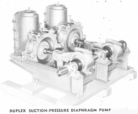
Stroke Adjustment and Capacity
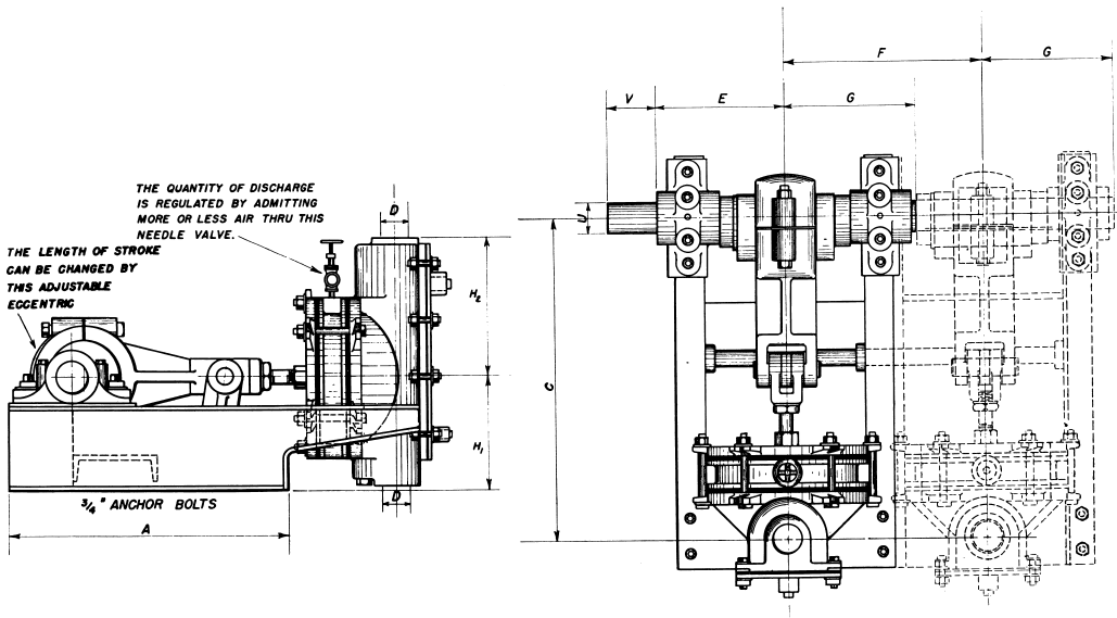
Regulation of capacity on all sizes of Suction-Pressure Diaphragm Pumps is made possible by means of an adjustable eccentric which allows for a wide capacity range. On the 1¼” and larger sizes, the capacity may be further regulated by admitting air in varying amounts to the chamber between the two diaphragms during the suction stroke through a small needle valve. The air thus admitted is drawn into the pump bowl through the lower valve, thus reducing the volume of pulp being pumped. This latter regulation of capacity can be made while the pump is operating, and is very simple.
Advantages of a Suction-Pressure Diaphragm Pump
Due to the novel construction features of the larger sizes of the Suction-Pressure Diaphragm Pump, several distinct operating features are apparent.
The simple method of capacity control—using the adjustable eccentric, and the small air-inlet needle valve for minor capacity adjustments, makes the pump practically automatic—requiring little supervision.
The diaphragms are each flexed to the same degree, at certain stages, and can never be distorted beyond their proper positions due to controlled maximum stroke. In other words, the pressure diaphragm is activated through a motion whereby it is at the extreme of flexing when the maximum pressure is being exerted, and returns to its normal molded position when the suction diaphragm is distended to the maximum, during the period of maximum suction. This is true of both diaphragms and maximum life is thereby secured.
The pump bowl has a relatively small volume, and not sufficient so that settling out of the pulp contained, during a shut down, would interfere with the lower or inlet valve. It can also be drained conveniently.
The side plate, constituting the entire side of the pump, is removable—giving access to valves, valve seats, etc. with minimum trouble.
To compensate for any variations in the pressure of the air contained in the chamber between the diaphragms, and the contents of the pump bowl, a small vent connects the two. As a safety factor, to prevent any possibility of pulp finding its way between the two diaphragms, a small, simple, one-way check valve is installed in this vent.
Height of Lift
Normally, the suction lift of a diaphragm pump is limited to that corresponding to 14 feet of water at sea level. This amounts to a lift of approximately eight feet when pumping pulp containing 50% solids when the specific gravity of the dry solids is 2.65.
In addition to the suction lift, Suction- Pressure Diaphragm Pumps will pump against a discharge head of up to 20 feet, depending on the specific gravity of material being handled.
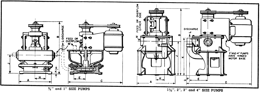
Suction-Pressure Diaphragm Pump Assembly

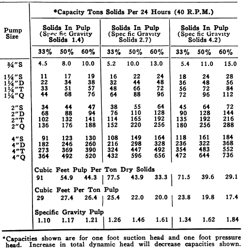
Suction-Pressure Diaphragm Pump Capacity
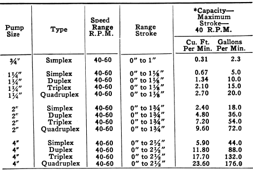
Specifications ¾” Size
The ¾” Suction-Pressure Diaphragm Pump is of slightly different construction from the larger sizes shown in the drawing above, but operates on the same general principle.
Source: This article is a reproduction of an excerpt of “In the Public Domain” documents held in 911Metallurgy Corp’s private library.
