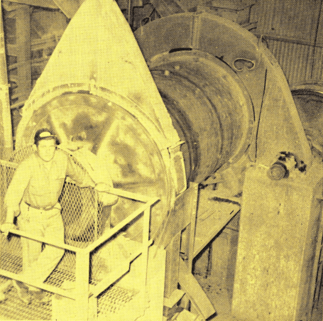
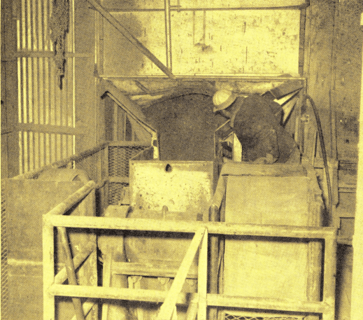
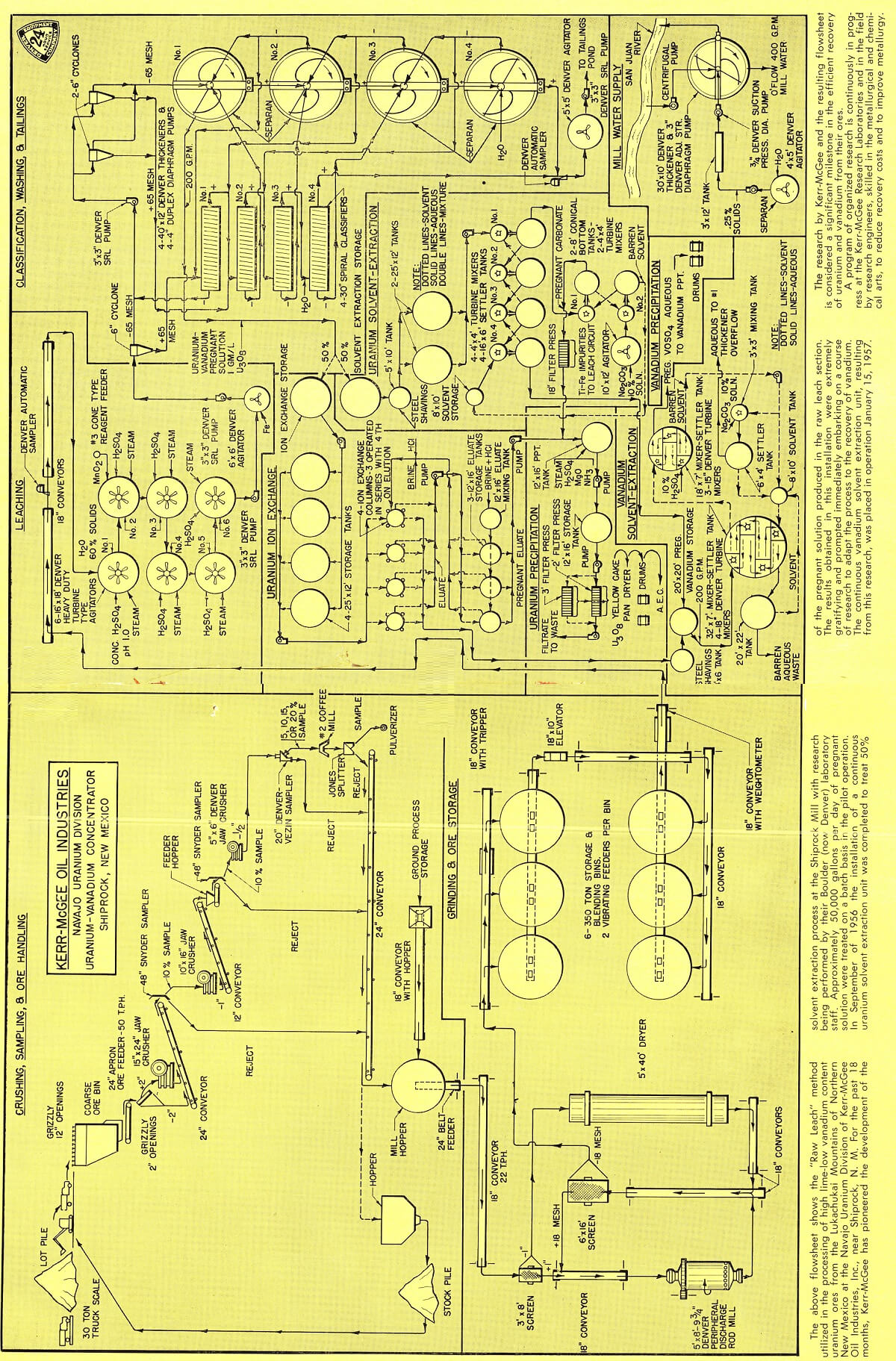
The plant was originally designed to treat uranium ores with low lime-high vanadium content from the Lukachukai Mountains. The process utilized is known as the “Acid Cure” and had been developed for the most part by the AEC to increase recovery of vanadium values. Briefly, it involved “pugging” the ore with 10% water and 400-500 lbs. of concentrated sulfuric acid. The product was allowed to cure for six or more hours to convert the uranium and vanadium values into water soluble salts. Acid consumption and labor resulted in high costs. With the increased mill capacity, the character of the ore feed from the new sources of supply changed to high lime-low vanadium content. The market for vanadium fell off and the AEC modified the milling contract to eliminate vanadium recovery. With the importance of vanadium recovery removed, and in order to reduce processing costs to a minimum, the method of processing was changed from “Acid Cure” to the “Raw Leach” method described in this article.
In addition to the change over to the “Raw Leach” method of processing, major changes have been made in the method of extracting uranium and vanadium values from the pregnant solutions. For the past 18 months, Kerr-McGee has pioneered the development of the solvent extraction process at the Shiprock mill with research being performed by their Boulder laboratory staff. Approximately 50,000 gallons per day of pregnant solution were treated on a batch basis. In September of 1956 installation of a continuous solvent extraction unit, to treat 50% of the pregnant solution produced, was completed. The results were extremely gratifying and research work commenced immediately to adapt the process for vanadium recovery. This commercial unit was placed in operation January 15, 1957.
How is Uranium Processed
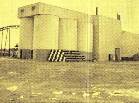
Uranium Ore assaying approximately 0.25% U3O8, slightly under 1% V205 and 6.5% CaCO3 is received at the mill from company owned and operated mines and from custom ore suppliers. Virtually all of the production from the company mines is carnotite-roscoelite ore from the Salt Wash of the Morrison formation. Deposits of ore occur in pockets and mining is by a modified room and pillar method. As new raises are driven old rooms are worked out and the pillars pulled on the retreat. Spotty occurrence of the ore pockets makes it almost impossible to accurately predict the size and location of the ore even with core drilling on close centers.
Ore haulage to the mill is by contract carrier on a per ton basis. Fourteen ton tandem trucks are used for the rugged trips from the mines to the mill.
Uranium Ore Crushing and Sampling
Uranium Ore is hauled by truck to the mill site, where it is weighed and a grab sample taken for moisture. Truck loads from each respective ore supplier are then dumped on a stock lot until 150-200 tons are accumulated at which time it is delivered to a 50-ton receiving hopper for passage through the crushing and sampling plant. Ore is fed from the receiving hopper by a 24″ apron feeder across a 2″ grizzly with the oversize being crushed in a 15″ x 24″ jaw crusher. The minus 2″ product is conveyed to a primary 48″ Snyder Sampler where a 10% sample is taken and dropped by gravity through a 10″ x 16″ jaw crusher for reduction to minus 1″. The crushed product is conveyed to a 48″ Snyder Sampler where a 5% or 10% cut is made. The sample drops to a 5″ x 6″ Jaw Crusher for reduction to minus ½”. The crushed product is passed through a 20″ Vezin Sampler capable of taking either 5%, 10%, 15% or 20% samples. Size of sample depends upon grade and quantity of ore sampled. The sample is further reduced in particle size and quantity, using a pulverizer, blender and Jones Type Splitter.
The crushing and sampling plant is operated five days per week on a two-shift per day basis. It is very compact, equipped with dust collecting equipment and designed so all sample rejects join a common 24″ conveyor which delivers to either a mill storage bin or to a receiving hopper for haulage to the crushed ore stockpile for blending or storage purposes. Capacity is 50 tons per hour. Approximately 60% of the ore as received from the mines is minus 2″. This, together with the friability and softness of the ore, accounts for the fact that only primary jaw crushing is required to prepare the material for rod mill feed.
|
|
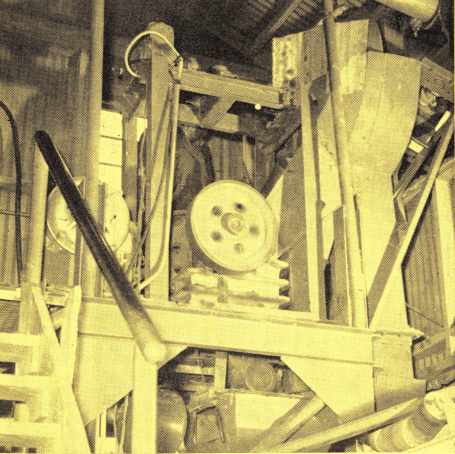
Tertiary sampling stage with 5″ x 6″ Jaw Crusher and 20″ Vezin Sampler |
Grinding Uranium Ore
Crushed ore is fed from the mill storage hopper by a 24″ belt feeder equipped with a variable speed rheostat controlled drive. Controls are located at the Rod Mill so the operator can control feed rate as desired. It is conveyed to a 3′ x 8′ vibrating screen with 1″ cloth. The plus 1″ material containing 3-4% moisture is conveyed direct to the 5′ x 8’9¾” Peripheral Discharge Rod Mill. The minus 1″ material containing 8-10% moisture is fed to a 5′ x 40′ direct fired Standard Steel Dryer for removal of moisture down to 3%. The dried product drops to an 18″ conveyor and thence to the rod mill discharge 18″ conveyor, which feeds the 6′ x 16′ vibrating screen.
|
|
|
The 6′ x 16′ vibrating screen equipped with 18 mesh electrically heated cloth is operated in closed circuit with the rod mill. The minus 18 mesh product is conveyed to one of six 350 ton blending and storage bins each of which is equipped with two vibrating feeders.
The minus 2″ size feed to the rod mill is not detrimental. The rods are reversed periodically to minimize the tapering effect on the feed end. Rod consumption is 0.25 lbs. per ton and the original liners have been in service since November, 1954. Feed to the grinding circuit is 25 tons per hour and the unit is operated on a three-shift basis. The rod mill consumes approximately 90 HP. Efficient wet dust collecting systems are installed throughout this section. Wet sludge is pumped direct to the leaching section.
Studies have been completed to determine the advantages of wet grinding versus dry grinding. Both offer advantages, with wet grinding having the edge.
Uranium Leaching
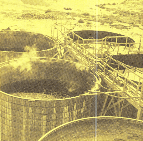
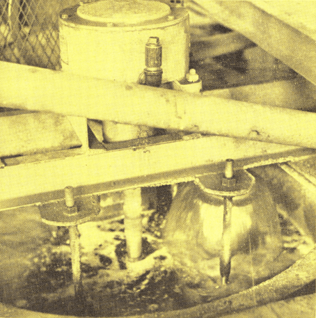
Ore ground to minus 18 mesh and properly blended for uranium and lime content is fed to an 18″ conveyor across a weightometer at a rate of 22 tons per hour. A Automatic Sampler provides a mill head sample. Water and concentrated sulfuric acid are added to a density of 60% solids by weight and pH of 1.0 The agitation section consists of 6-only, 16′ x 18′ Heavy Duty Agitators equipped with 60″ diameter Turbine Type Propellers. Live steam is added to each unit to maintain 125°F. pulp temperature. They are designed for 16-hour contact of the pulp. Flow through the units is in series, with one unit maintained as a standby. The No. 1 and No. 2 Agitators operate at 73 RPM and draw approximately 13 HP. The remaining four units operate at 63 RPM and consume approximately 10 HP. The first two Agitators are operated at higher speed to insure suspension of the coarse material until the acid has had sufficient time to react and provide buoyancy to the slurry. Additional horsepower was provided in the design should it prove that more power was required for extraction. At the present, uranium extraction is 97% and analysis indicates 2% of this loss is in the plus 35 mesh fraction, indicating finer grinding will increase extraction to 99%.
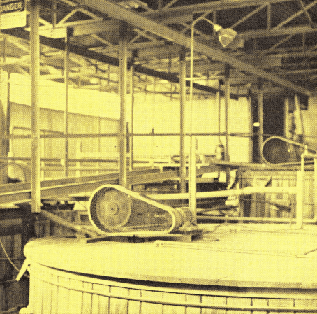
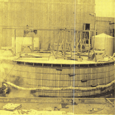
All units are mounted on the same level with a common service walkway. Each tank overflows at top through a baffle box to eliminate short circuiting and is provided with an air lift to insure removal of any coarse material which might accumulate in the bottom of the tank. Both the overflow and air lift discharge at 60% solids. Pulp levels and launders are arranged so that in the event of trouble, any unit may be by-passed without shutting down the entire section. Superstructures are mounted directly on 4″ stave wood tanks. Wood bottom wearing plates are provided. Bands are protected from corrosion by polyethylene and grooved staves. The No. 1, 2 and 3 tanks are covered and vented to carry off the acid and CO2 fumes.
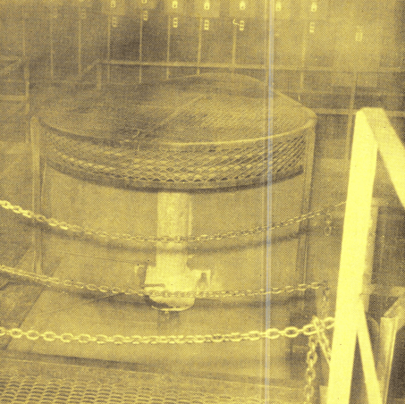 One of six only 16′ x 18′ Heavy Duty Turbine Type Agitators installed in Raw Leach Section One of six only 16′ x 18′ Heavy Duty Turbine Type Agitators installed in Raw Leach Section |
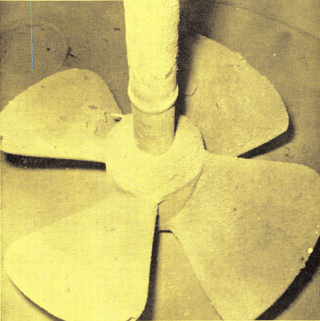 A 30″ Turbine Type Propeller Agitator for mixing iron powder with pulp A 30″ Turbine Type Propeller Agitator for mixing iron powder with pulp |
Units are designed for removal and replacement of a complete propeller assembly to minimize shutdown time in the event of difficulty.
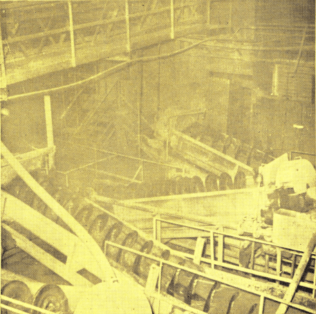
To date, the units have been in operation nine months and only show slight wear even with the coarse nature of the ore. Propellers and shafts are rubber covered and are provided with an Acme thread connection and seal for simplicity in removal and replacement of propellers.
Additional sulfuric acid is added to the No. 2, 3, 4 and 5 Agitators to maintain a pH of 1.0. Average total acid used is 200 lbs. per ton of head feed. Five lbs/ton of MnO2 is added to the No. 2 Agitator as an oxidant to increase the uranium dissolution.
The agitator discharges to a 3″ x 3″ SRL Pump which pumps to a 6′ x 6′ Turbine Type Agitator where 1 lb. iron powder per ton of solids is added to reduce ferric iron to ferrous iron.
Classification and Thickening of Uranium
In general, a cyclone sand-slime separation is made on the leach agitator slurry with the plus 65 mesh sands being washed countercurrent in four only 30″ spiral classifiers and the minus 65 mesh slimes washed in four only 40′ x 12′ Thickeners. Sixty per cent of the solids appear in the sand circuit and 40% in the slime.
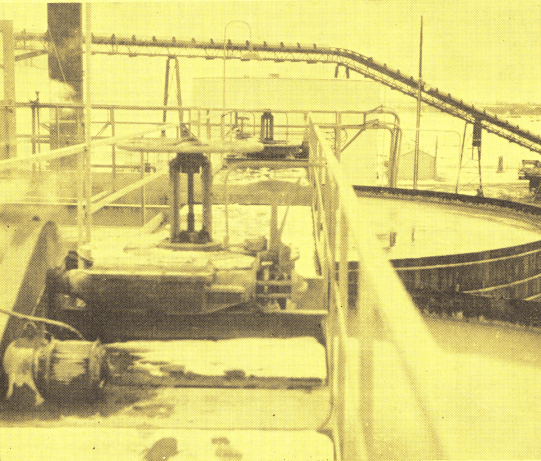
The slurry from the iron reduction agitator is delivered by a 3″ x 3″ SRL Pump to a 6″ cyclone.
The minus 65 mesh slime and the No. 1 classifier overflow join and are pumped by a 3″ x 3″ SRL Pump to two 6″ cyclones in parallel. Sands from these cyclones drop to the No. 2 classifier and the slime overflow together with the No. 2 classifier overflow and part of the solution overflow from Thickener No. 2 make up the feed to the No. 1 Thickener.
To minimize dilution and provide proper washing action, a portion of the overflows from Thickeners No. 2, 3 and 4 are added as wash to No. 1, 2 and 3 classifiers respectively. Fresh water is added to No. 4 classifier. Classifier sands are washed by countercurrent decantation in the four units and go to final tailings.
The remaining portion of Thickener overflow solution, not used as classifier wash water, moves from No. 4 Thickener to No. 3 to No. 2 to No. 1. Fresh water is added to No. 4. It has been found that hindered settling takes place if Thickener feed exceeds 14% solids.
10% solids feed to the Uranium Thickeners is desired. A portion of the Thickener overflows is recycled to accomplish this. One and one-half inch centrifugal pumps elevate the thickener solution overflows and discharge into baffled launders where it mixes with the Thickener underflows which are metered by 4″ Duplex Diaphragm Pumps. This aids in breaking up floes and reduces soluble loss in the thickener circuit. It also provides better dispersion of the settling agent.
Clear uranium-vanadium pregnant solution overflows the No. 1 Thickener at a rate of 200 GPM. Uranium concentration is 1.0 gm. per liter. Separan No. 2610 settling agent is added at a rate of 0.10 lb. per ton solids to the Thickeners to improve settling conditions. The separan is slurried to 25% solids for addition.
Uranium Tailings
The underflow from No. 4 Thickener and the sands from the No. 4 classifier are blended in a 5′ x 5′. Heavy Duty Agitator. A 3″x 3″ SRL Pump pumps the slurry at 40% solids through a 4″ line a distance of 1500′ to the tailings disposal area.
Uranium Recovery IX Method (Ion Exchange)
As mentioned previously, 50% of the pregnant solution which is the clear overflow from the No. 1 Thickener is sent to the batch operated ion exchange units referred to as IX columns. The pregnant liquor containing both uranium and vanadium values is pumped to the four ion exchange columns. In this process, the uranium is extracted from the sulphate solution and deposited on the ion exchange resin. Each column has three layers of sized gravel for filter purposes in the bottom with a layer of resin on top of the gravel and solution flows from bottom to top. The columns are operated with three in series receiving new feed and a fourth being eluted (washed) with brine and hydrochloric acid to strip the uranium values from the resin.
Three stage elution with 12′ x 16′ holding tanks is used to build up the uranium content of the elutate to 12 gms/liter. Brine and hydrochloric acid are mixed in a propeller agitated 12′ x 16′ tank. After the No. 1 feed column becomes loaded, eluate from the No. 1 storage tank is used to strip the freshly loaded column. This becomes pregnant eluate and goes to precipitation. The resin eluate is then further stripped with eluate from No. 2 and No. 3 storage tanks which are then advanced to the No. 1 and No. 2 tanks respectively. Fresh brine and HCl are added to the No. 3 tank. After three stage elution, the resin in the column is again ready to receive pregnant sulfate solution.
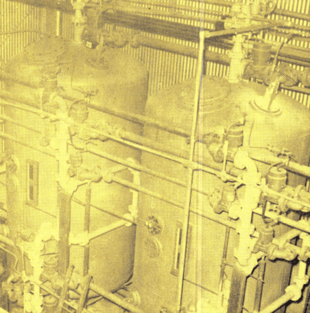 Ion Exchange columns for extracting uranium from pregnant sulfate solution. Ion Exchange columns for extracting uranium from pregnant sulfate solution. |
 General View Uranium Solvent Extraction Section with mixer tanks inserted in 16′ x 6′ Settler Tanks. General View Uranium Solvent Extraction Section with mixer tanks inserted in 16′ x 6′ Settler Tanks. |
Uranium Solvent Extraction Recovery System
The remaining 50% of the pregnant solution thickener overflow is sent to the new commercial continuous solvent extraction system.
Steel shavings are added to the liquor in a 5′ x 10′ tank with a false bottom, to reduce all ferric sulphate to ferrous sulphate with an EMF of 275 to 300 desired. This flows to the solvent extraction system which includes a series of four mixer- settler units in series as the extractor system and two mixer-settler units as the stripping section. This section is of unique design in that the 4′ dia. mixer tanks are set inside the 16′ x 6′ settler tanks. Installation costs were reduced in that valves and piping were eliminated.
In general, the pregnant solution referred to as “aqueous” is introduced to the No. 1 mixer and the solvent is introduced to the No. 4 mixer. The four mixers operate countercurrent with 100 GPM aqueous moving one direction, and 20 GPM solvent moving the opposite direction. The aqueous flows between units by gravity and the solvent by airlifts.
The solvent is prepared by mixing two organic phosphate compounds and dissolving them in high flash point kerosene. This solution is then violently mixed with the pregnant liquor containing the dissolved uranium. Since the solvent has a greater affinity for the uranium in an acid medium than the aqueous sulphate solution, the uranium is transferred into the organic phase. The mixture of the organic and aqueous liquids flows to 16′ x 7′ settling tanks where the lighter pregnant organic liquid collects on top of the aqueous solution.

In the countercurrent system the barren solution from mixer-settler No. 4 is pumped to vanadium recovery storage and the pregnant organic solvent from the No. 1 mixer-settler unit is sent to the stripping section of the mixer-settler units.
In the stripping section, two 4′ x 4′ mixer units and 8′ cone bottom settlers are utilized in countercurrent flow much the same as in the extraction section. The pregnant organic solution is introduced to the No. 1 stripping mixer and 10% soda ash solution is introduced from a 10′ x 12′ propeller agitated storage tanks to the No. 2 mixer. The soda ash solution has a greater affinity for uranium and with high agitation, uranium is separated from the organic solvent and joins the soda ash solution. The stripped solvent from the No. 2 mixer- settler tank is sent to an 8′ x 10′ tank and returned to the No. 4 mixer-settler unit of the extraction circuit to meet more pregnant aqueous solution.
The soda ash solution containing 50 gms. per liter of uranium values is pumped through an 18″ filter press for removal of iron and titanium impurities and then sent to the precipitation section. The impurities sludge is returned to the leach agitators.
Solvent loss is 0.5 gal. per 1000 gallons of pregnant aqueous. Tailings are 0.005 U3O8 gms. per liter.
Experiments are being conducted to determine minimum speed and horsepower requirements of the mixers to provide the most economical extraction and stripping. All mixers have 18″ diameter vertical turbine propellers. Two mixers, in extraction, operate at 150 RPM and consume 1.5 HP. The other two operate at 200 RPM and consume 2.7 HP. The two in stripping consume 1.2 HP and operate at 150 RPM.
Uranium Precipitation Process
The pregnant eluate and soda ash solutions from the Ion Exchange and Solvent Extractions systems are combined in a 12′ x 16′ propeller agitated tank. The pH is adjusted to 3.0 with sulfuric acid. Steam is added to bring solution to the boiling point to drive off CO2. MgO and NH3 are added to precipitate uranium. Actually, ammonia is cheaper, however, the MgO precipitates large crystals making subsequent filtration easier.
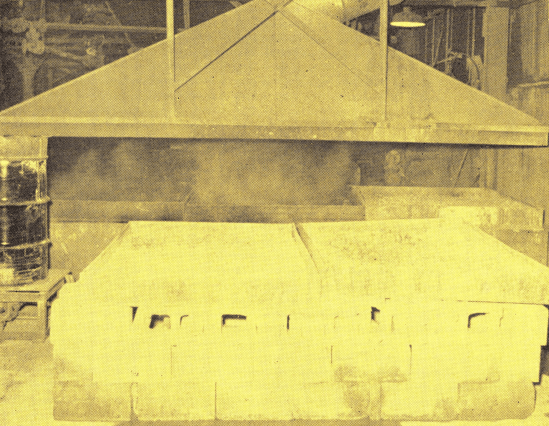
The precipitated slurry is pumped to a 12′ x 16′ propeller agitated holding tank and thence split to a 24″ 20-frame Burwell filter press and a 36″ 20-frame standard filter press. Filtrate goes to waste and the uranium concentrate (yellow cake) assaying 79% U3O8 drops to pan dryers. After drying to 4% moisture it is packed in drums and shipped to market.
Vanadium Recovery Solvent Extraction Method
The barren solution from the uranium ion exchange is passed through a 4′ x 6′ false bottom tank containing steel shavings to reduce the ferric iron to ferrous and provide the proper EMF for vanadium solvent extraction. It is combined with the barren solution from the solvent extraction uranium recovery system and stored in a 20′ x 20′ tank. The extraction system includes four only Vertical Turbine Mixers with 18″ propellers and 7½ HP motors. The stripping section includes three only Mixers with 15″ vertical turbine propellers and 5 HP motors.
The extraction mixers are installed in a 32′ diameter by 7′ deep tank with three parallel partitions. Within each partition is a mixer and settler chamber. The same design is employed in the stripping section with a tank 18′ x 7′. This reduced installation cost considerably as virtually no expensive piping is required. The tanks have covers eliminating the need of a building.
The aqueous sulphate solution, containing vanadium values, is introduced to the No. 1 feed mixer and solvent (mixture Di-2 ethyl hexyl phosphoric acid, tributyl phosphate, and kerosene) is introduced into the No. 4 mixer. The aqueous and the solvent travel countercurrent, with the pregnant solvent being removed from the No. 1 mixer-settler unit and the barren aqueous being removed from the No. 4 settler unit. The barren aqueous collects in a 20′ x 22′ tank as waste solvent.
The pregnant solvent is then introduced to the No. 1 mixer settler unit of the stripping section with 10% H2SO4 solution being introduced to the No. 3 mixer-settler unit for countercurrent flows. The vanadium values are contained in the sulphate solution which is sent to the vanadium precipitation section.
The stripped solvent is pumped to an 8′ x 10′ solvent storage tank and reused in the No. 4 mixer in the extraction section. A small amount of uranium values are contained in the barren solvent, hence 5% of same is passed through a 3′ x 3′ mixer and 6′ x 4′ settler. A
10% solution of Na2CO3 is added to the mixer and the carbonate aqueous containing the small amount of uranium joins the No. 1 thickener overflow.
Reagents Needed to Process Uranium
Those are in a 40’x80′ warehouse storage for dry reagents. Truckload shipments to mill.
- H2SO4 — Stored in 10 only 100 ton capacity tanks. Pumped to distribution points through control meter.
- Ammonia — Stored in 20,000 gallon insulated tank. Pumped to mill distribution through control meter.
- Soda Ash—100 pound bags. Elevated to propeller agitated tank and pumped through control meter.
- HCl—Stored in 6000 gallon tank. Pumped through control meter by means of an acid-proof pump.
- MgO—100 pound bag—fed manually to precipitation agitator in the uranium precipitation section.
- Brine—Stored in concrete tank. Slurried in 6’x6′ agitator and pumped to eluate mixing tank.
- MnO2—100 pound bags. Fed by a No. 3 Cone Type Reagent Feeder to No. 2 leach agitator.
- Separan—100 pound bags added to mixer and water slurried at .25% solids and pumped to thickeners.
- Phosphoric Acid—Received in 55 gallon stainless steel drums, hand pumped to solvent mixing tank.
- Napoleum — No. 470 high flash point kerosene (160°F.) — stored in 6000 gallon tank. Pumped to solvent mixing tank for make-up of organic solvent.
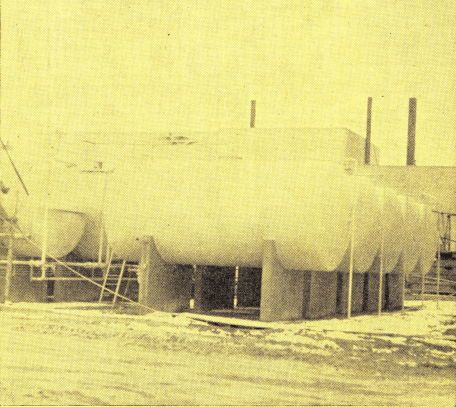
Ten only 100 Ton Capacity mild steel concentrated H2SO4 storage tanks.
Energy/Power to Produce Uranium
Three natural gas fired, water cooled engine generators each rated at 350 KW furnish 3 phase, 60 cycle, 480 volt power. Normal consumption is 700 KW. Natural gas rated 1000 BTU per cu. ft. is available. A standby 85 KW generator is available for emergencies.
Boiler
A 150 HP water tube boiler, natural gas fired, supplies steam to mill. A 150 HP boiler is available for standby or peak loads. Boiler feed is softened water.
Water Supply
Water is pumped from the San Juan River, using a centrifugal pump. Due to extreme solids content of water it must be treated prior to use in plant.
Approximately .06 lb. Separan per ton water at .25% solids is added to settle thickener slimes. The amount varies with solids content of river water which may run 15% during runoff season. Separan is mixed in a 4′ x 5′ Agitator, pumped to a 3′ x 12′ storage tank and metered by ¾” Suction Pressure Diaphragm Pump to the thickener feed.
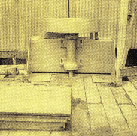 Vertical Turbine Mixer installed in Vanadium Solvent Stripping Section. Vertical Turbine Mixer installed in Vanadium Solvent Stripping Section. |
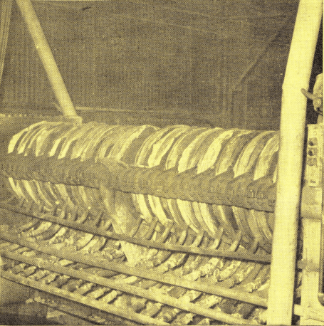 A 24″ 20-Frame Continuous Pressure Filter for removal of water from uranium concentrate. A 24″ 20-Frame Continuous Pressure Filter for removal of water from uranium concentrate. |
The river pump delivers against a 110′ TDH to a 30′ Thickener. The pump is suspended by cable and raised or lowered as the river level changes. Underflow from the thickener is metered back to the river by a 3″ Adjustable Stroke Diaphragm Pump. Overflow is pumped by a centrifugal pump to two 30′ x 30′ water storage tanks at the mill site.
Water from the 30′ x 30′ storage tanks is pumped at 85 psi through 6″ mill distribution line with 4″ centrifugal pump driven by a 25 HP motor. Opening of fire hose valve starts a standby gasoline powered pump, which is available for emergencies.
Water Softening
Water from mill’s storage tank passes through a sand filter and then to a 20 GPM zeolite water softening system. Brine is used for back washing. Softened water is supplied to the boiler and for cooling power engines.
Uranium Laboratory
A completely modern laboratory provides prompt and thorough analytical results necessary for efficient mill operation. Ore lots, concentrate lots, solvent extraction and carbonate pregnant liquors assays are all run by chloroform extraction balance method. Low grade solution assays up to 1 g. per liter uranium for mill control are run by fluorimeter and results are available within one hour. The chemical and technical staff includes several Navajo Indians.

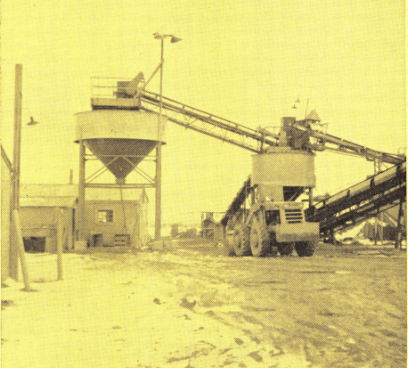 General view of crushing and sampling area, showing mill and stockpile receiving hoppers