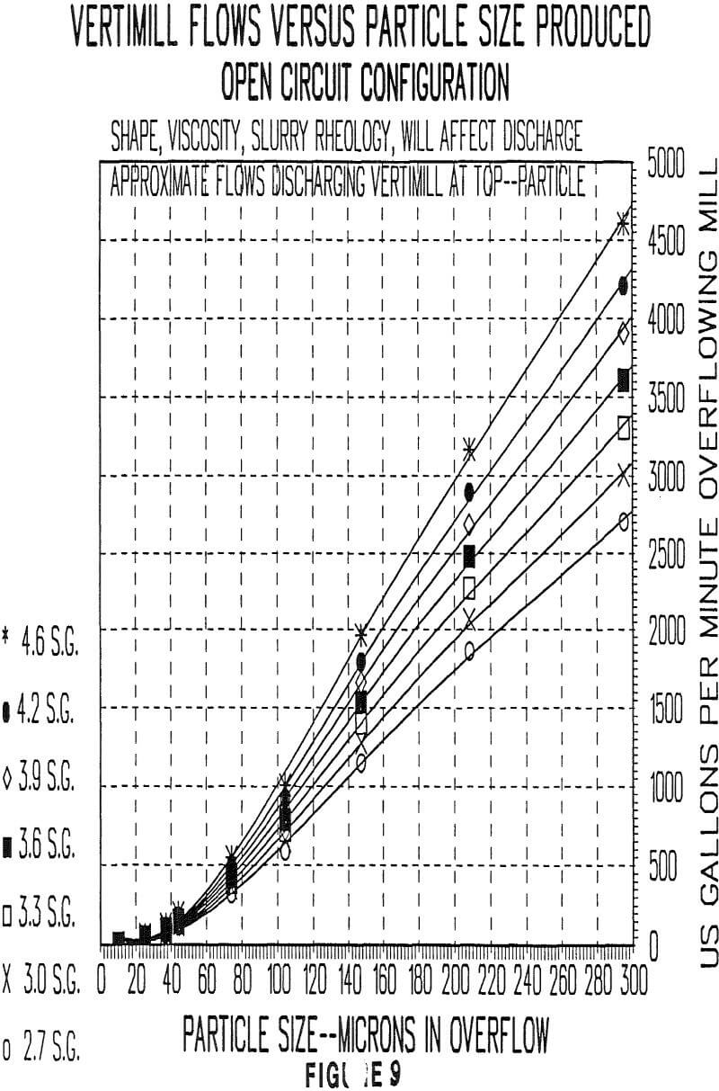
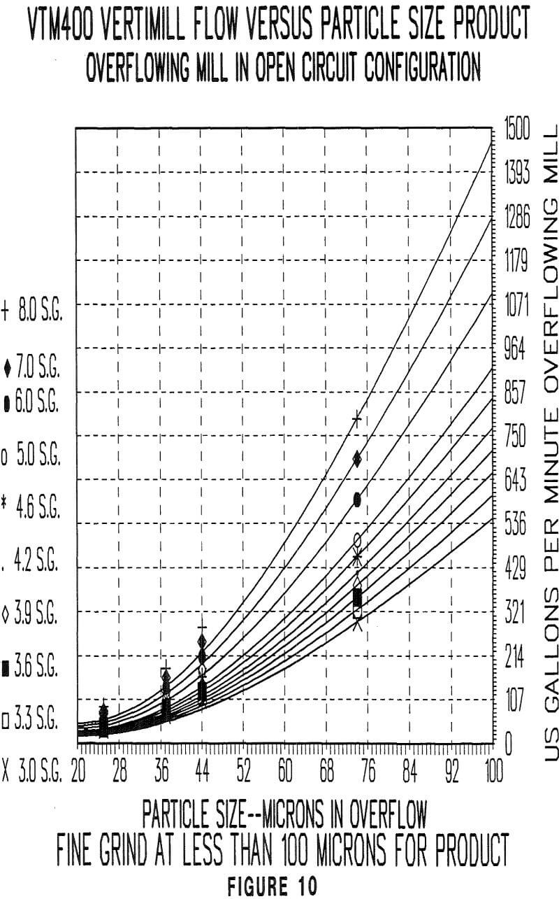
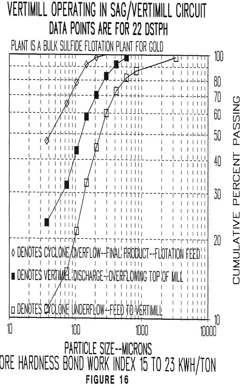
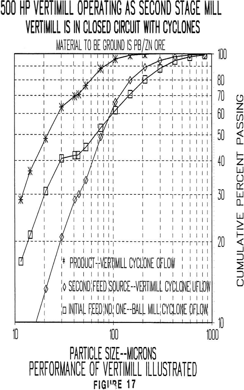
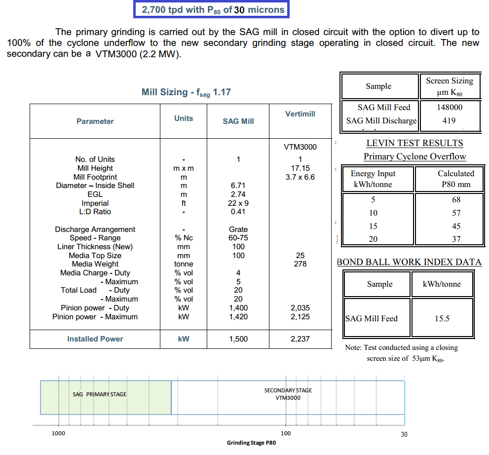
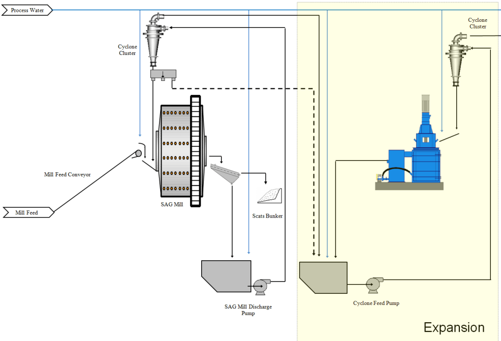
This was a case study for an expansion of a 2200 TPD SAG Mill operation. The client wanted to increase the plant to 2700 TPD @ 30um. Some plant samples were taken, work indexes obtained and data simulated. As it turns out a single 3000HP Vertimill would get that done.
The applications of the VERTIMILL continue to expand in number. The variety of applications being tested and operated are demonstrating the versatility of the machine. The VERTIMILL initially was developed to meet the needs of the fine grinding industry. It has been expanded to include coarse grinding in copper, lead, zinc, gold, aragonite, calcium carbonate, plants.
Modes of Operation
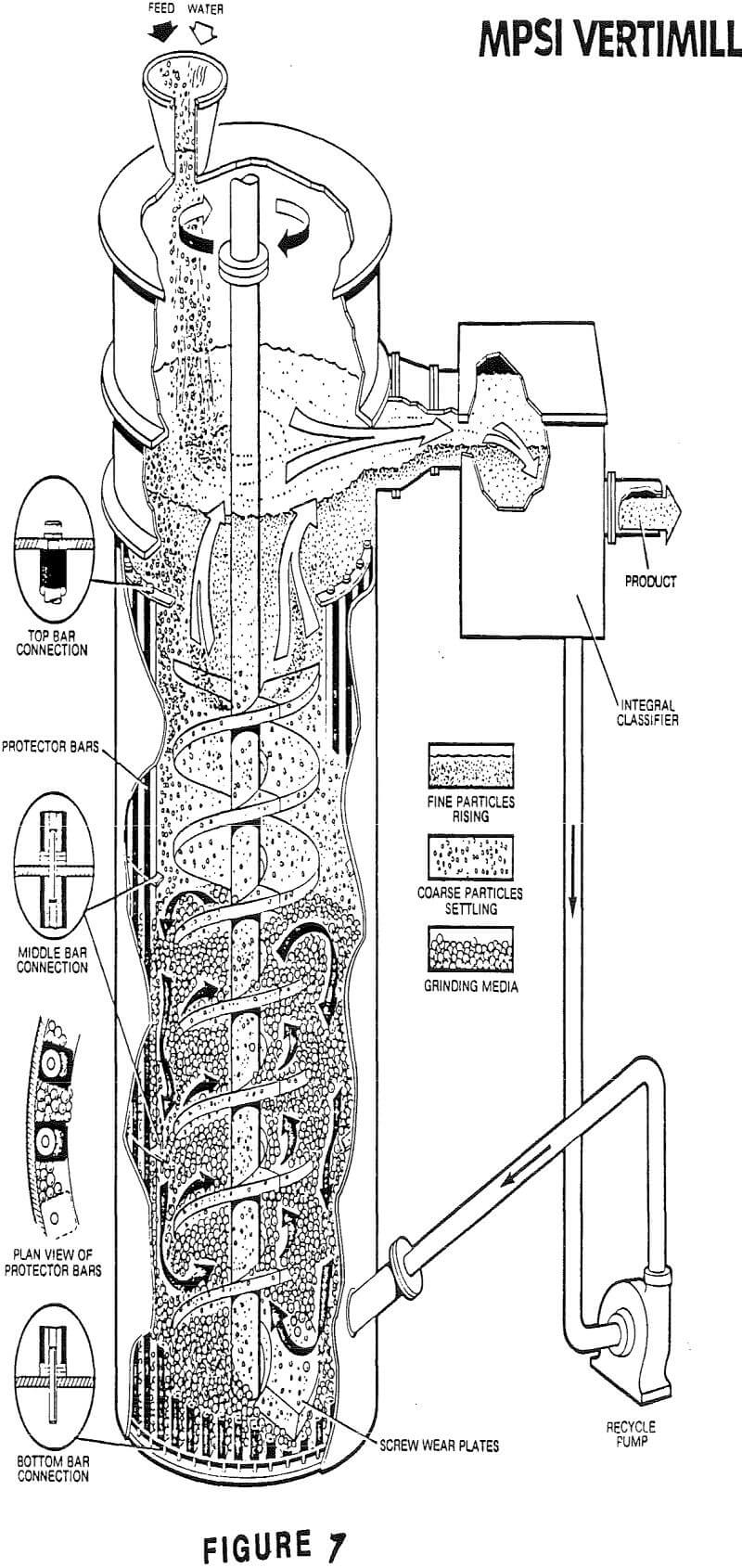
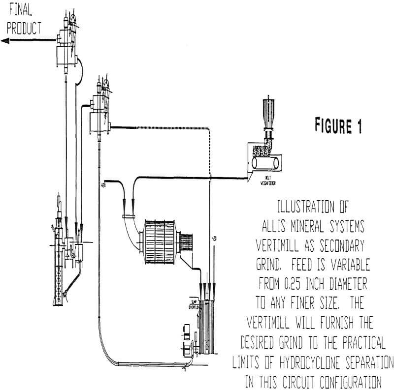
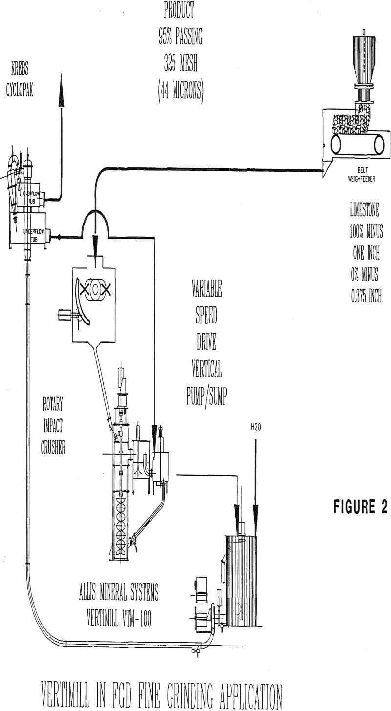
A. Closed circuit with feed directly into VERTIMILL and VERTIMILL discharge to a cyclone feed sump.
B. Closed circuit with feed prescalped by a classifier and the classifier coarse fraction feeding the VERTIMILL at the top or the bottom.
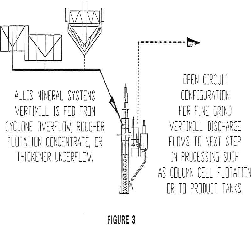
C. Open circuit with feed into the bottom of the mill.
D. Open circuit with the feed prescalped by a classifier and the classifier coarse fraction feeding the bottom of the vertimill.
E. Batch grinding
Applications of the Vertimill
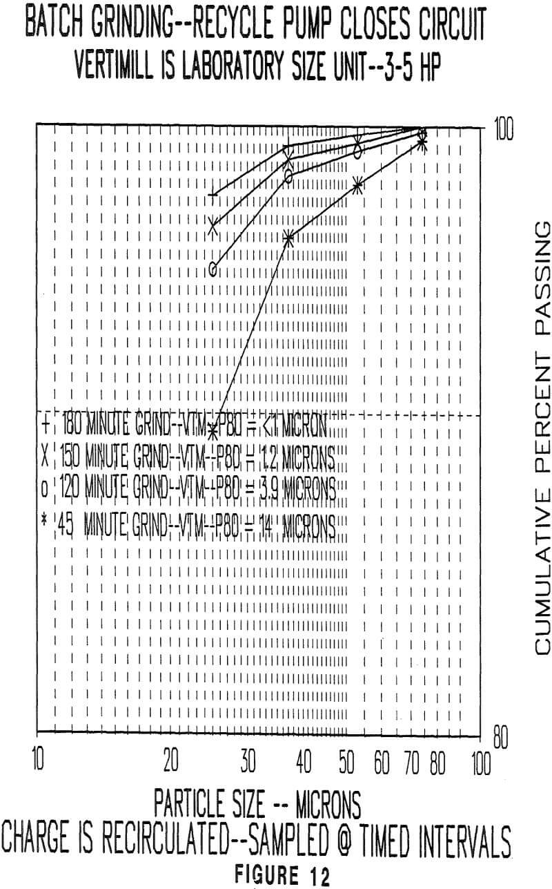
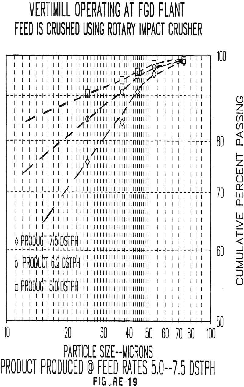
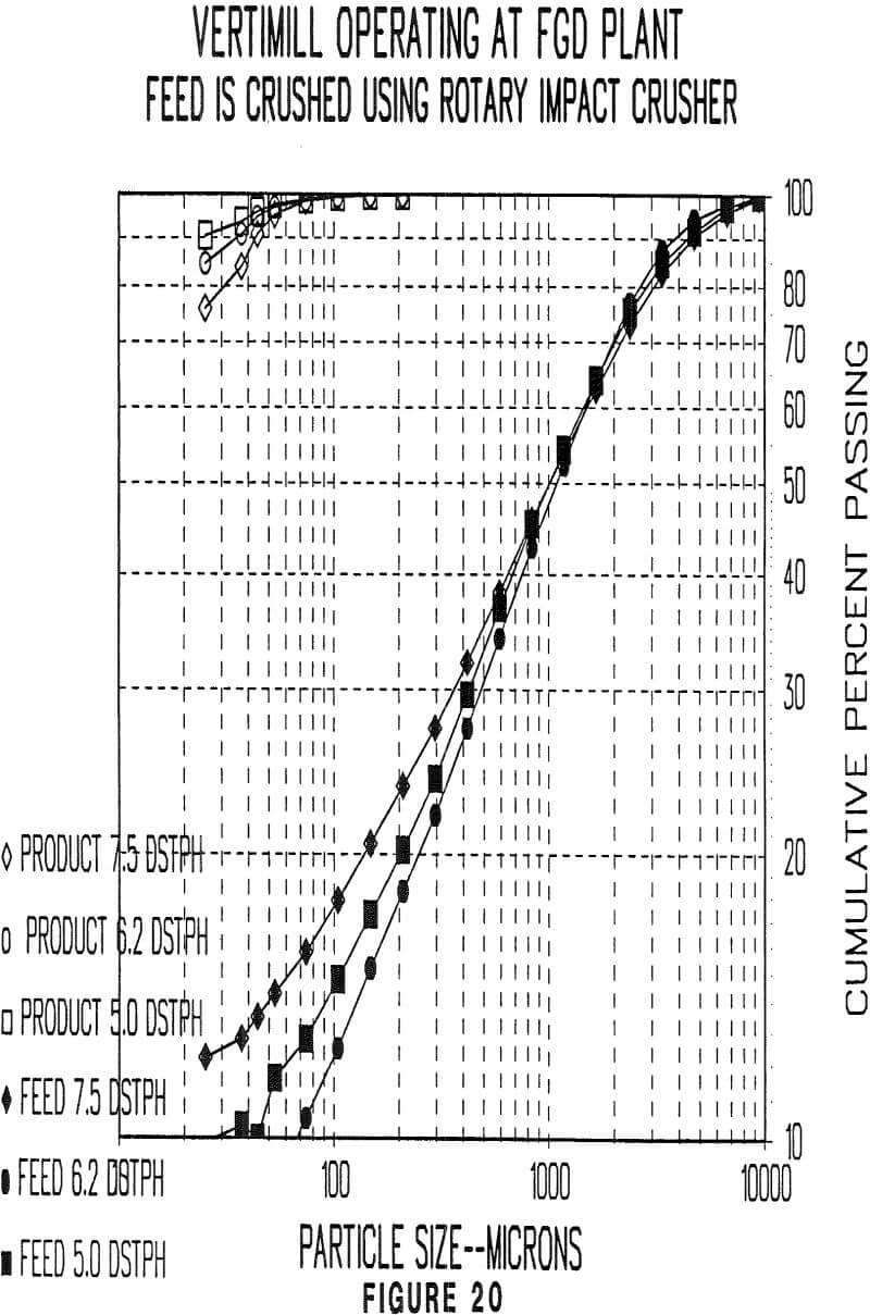
The data points were generated by a pilot scale mill. Note that the coarse product is maintaining a 200 mesh cutpoint while the 80 percent cut point of the four samples shown here are ranging from 14 microns to less than 1 micron.
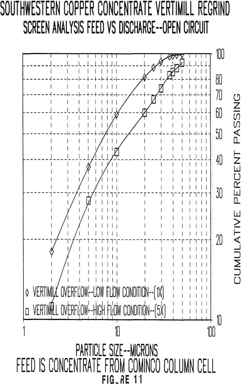
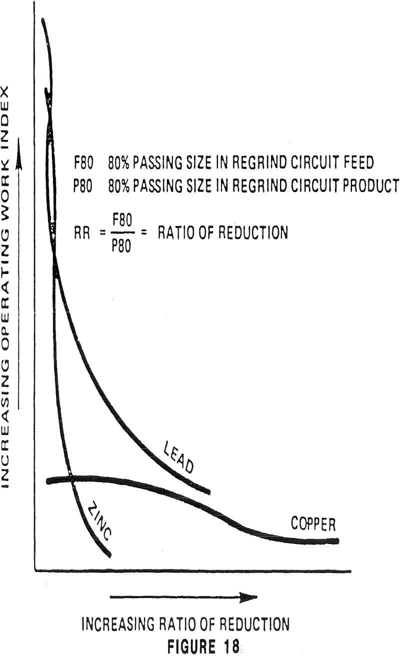
Regrinding concentrates to a fine size is difficult to compare to a ball mill. The main reason for this is the extreme unpredictability of the quantities to be reground and their hardness as the grade, recoveries, and flotation response all combine to make the circuits unstable. Of particular concern is the ratio of reduction. Some ores require the primary grind to be finer than others when metallurgical testwork determining the grind/recovery response is evaluated. The economic implications of throughput versus costs are determinators of the desired grind in the primary grind.
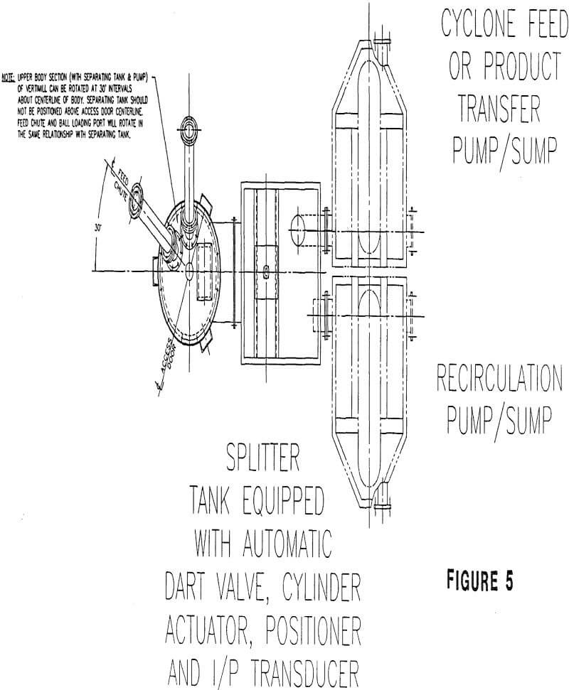
Picture shows the interior of the splitter tank which handles vertimill discharge the ‘splitter tank’ also provides control for the recycle loop for the overflow out of the vertimill. The orifice in the foreground is located in a rubber covered plate. This is the location where the solid polyurethane ‘dart valve’ resides. It’s function is to control the flow to the recycle pump. This valve is typically actuated by a cylindrical actuator fitted with a positioner. The input signal is usually a 4—20 milliamp signal that is fed to a current/pneumatic transducer (i/p). This feeds the positioner to control the flow to the recycle circuit. The desired recycle flow can be manually set or can be the output of a level control system on the recycle pump/sump.
The ‘overflow pipe’ in the upper right hand side of the ‘splitter tank’ directs the product of the vertimill to further processing in an open circuit grind or to a cyclone feed pump in closed circuit grind flowsheet.
The upper bar is the mounting plate of the cylinder actuator.
