Table of Contents
The work covered in this report is a continuation of an earlier feasibility study by the Federal Bureau of Mines and points out improvements in the skull-melting method for casting reactive metals such as titanium, zirconium, and hafnium. Machined graphite molds with laminated sections can be reused many times. Large tube sections can be produced by spin casting. Graphite powder is the best expendable mold material, but binders for this use must be compounded carefully. The effects of current and furnace atmosphere on the dependent variables of the casting technique are shown.
Because of developments in casting technology for titanium which eliminate the basic problems of melting and pouring the metal, opportunities for improvement in the method have increased. The mold material and gate and
riser configurations require particular attention. The limits of application of the casting method have yet to be defined. New knowledge in any one of these areas could result in marked improvements and simplifications in casting methods.
Titanium castings became available commercially in 1958. Several firms are engaged in casting titanium and titanium-alloy shapes. Production of true spin castings has been announced. The Bureau has furnished two consumable electrode arc-casting furnaces to government laboratories, and there are indications that nine furnaces of this type are operating or under construction in this country and abroad.
Titanium technology gained early impetus from the demand for titanium in military aircraft. Changes in military concepts caused a severe decline in requirements for titanium in 1957, and commercial development of titanium for chemical process applications where corrosion is a problem was undertaken with increased emphasis. Zirconium cast shapes are being considered for nuclear reactor applications when the number of pieces do not justify costly forging dies. Because of the difficulties in forging hafnium, casting may become particularly valuable for manufacturing sections.
This paper which shows the ramifications of the reactive-metal casting process is an extension of earlier Bureau work covering development in titanium casting technique up to July 1955. For background on the subject, the reader is referred to that work and to the summaries of casting technology by the Defense Materials Information Center at Battelle Memorial Institute
Acknowledgments
The support of Army Ordnance is gratefully acknowledged for initial studies on titanium casting development, beginning in 1953. Mr. Stuart V. Arnold of the Watertown Arsenal has contributed significantly to the program. Studies on zirconium and hafnium casting were sponsored by the Pittsburgh Naval Reactors Operations Office of the Atomic Energy Commission (AEC), with the technical support of the Atomic Power Division of Westinghouse Electric Corp. Mr. Frank Kerze, Jr., of AEC, has given many valuable technical suggestions. Certain phases of the operation were carried out through the auspices of the San Francisco Operations Office of AEC and the University of California Lawrence Radiation Laboratory. Since 1956, the major support of the titanium casting program has been through Bureau of Mines appropriations.
Industrial groups cooperating with the Bureau include E. I. duPont de Nemours & Co. and Columbia Southern Chemical Corp. for environmental testing of valves; Electric Steel Co. of Portland, Oreg., on spin-casting techniques and core-forming methods; Chase Brass and Copper Co. on extrusion and evaluation of spin-cast billets; Kolkast Industries, Inc., and Precision Casting Co. on the use of ceramic, frozen-mercury-type molds in titanium casting. The Hills-McCanna Co. furnished patterns for the diaphragm valves.
Experimental Procedures and Results
Casting Method Furnace Operation
The consumable electrode skull-casting technique, developed by the Bureau of Mines for titanium, is considered to be the best method of producing titanium and zirconium castings. Figure 1 shows a skull-casting furnace in which the electrode, consisting of a premelted ingot of the metal to be cast, is
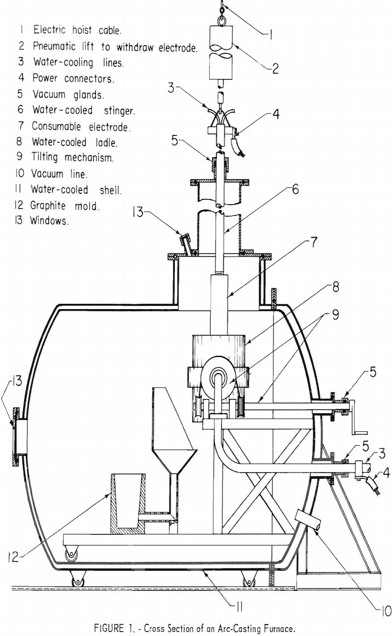
mounted to the “stinger” shaft with a threaded joint. The water-cooled crucible is charged with a previously produced skull and a quantity of scrap (not to exceed 20 pct. of the expected pour weight), and the furnace is evacuated. When an arbitrary limit of 50 µ is reached, the electrode is connected to the power supply, and the casting cycle begins. Upon striking an arc at 2,000 to 3,000 a., a diffuse, nonconsuming arc is observed, and the current is raised to the operating level of approximately 1,000 a./in. of diameter of the crucible ,. and melting begins immediately. The electrode is advanced to compensate for consumption. When the current is in the range of 8,000 a. d.c., a typical melting rate for titanium is 10 lb./min., and for zirconium, 14 lb./min. The pressure in the 6-in.-dia. vacuum line may be in the range of 50 to 150 µ., depending upon the gas content of the electrode. When the required weight is consumed, the arc is extinguished, the electrode is extracted, and the crucible is poured, under the control of automatic sequence switches—all within 4 to 8 sec.
Furnace Design
Besides the furnace design shown in figure 1, a larger unit (fig. 2) was constructed with some improved features. The casting chamber, which enclosed the tilt-pour crucible was of box-shape construction with outside reinforcement to prevent collapse under vacuum. The chamber was 6 ft. high, 5 ft. wide, and 6 ft. deep. The full-size door allowed use of a regular motorized fork lift to remove castings and exchange crucibles. The chamber was evacuated by two 5-hp. 110-cu.ft./min. mechanical pumps. The pressure in the furnace was normally in the range of 150 µ during the operation.
A turntable was installed in the floor of the chamber to allow placement of several molds. With this arrangement, a heat may be poured, the electrode lowered, the arc reignited, and additional pours made with a single pumpdown. This furnace was originally fitted with a “sliding shoe” type of electrode assembly. The consumable electrode was connected to a massive copper block having three independently sprung graphite-faced shoes, which contacted the inside of a double wall water-cooled tube. This tube served as the power contact and housed the electrode. Electrode motion was effected by a winch and cable mounted inside a chamber at the top of the power contact tube.
The graphite facing of shoes was not included in the original design but was added to avoid uneven current flow, development of hot spots, and accidental spot-welding of metallic shoe faces to the power contact tube. There was some apprehension that graphite abraded from the shoe facings would fall into the molten pool; however, this, did not occur.
The one advantage of this electrode assembly was that larger consumable electrodes could be supported within a given overhead clearance. The chief disadvantage was awkwardness in mounting consumable electrodes. Because the copper shoe block was totally enclosed, it had to be removed from the power contact tube to affix the consumable electrode. Even then, the block was
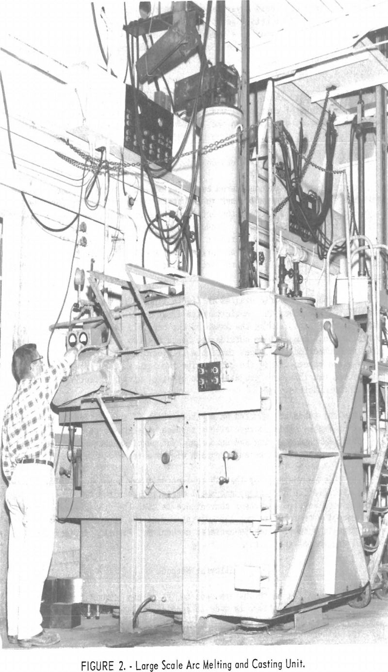
difficult to grip while making the threaded connection commonly used. This disadvantage probably could have been overcome by slight modifications in design, but a period of trial operation revealed that limitation of arc power restricted the maximum pour to a weight that could be accommodated in the available overhead space by a shaft or “stinger rod” type of electrode assembly. Accordingly the more familiar and straightforward shaft suspension shown in figure 2 was adopted.
Crucibles up to 14-in. in diameter have been used in this equipment, and the maximum weight of cast metal was 195 lb. titanium, or 280 lb. zirconium. The maximum current available in the laboratory slightly exceeds 12,000 a., which is probably 2,000 a. less than the ideal for the 14-in. crucible.
Safety Consideration
Remote operation is considered essential in arc casting because of the incidence of disastrous explosions in industrial titanium-melting furnaces. To protect the operating crew, the entire melting and pouring cycle was controlled from a remote location. Because of the nonroutine nature of most operations, researchers considered it essential to provide visibility into the furnace. To achieve this, an optical system was installed to project images of the molten metal and the arc on a ground-glass screen in the control room.
The furnace schematic diagram in figure 1 shows that two view ports are mounted over the crucible. Angle-mounted first surface mirrors were installed over the view ports, aiming the image of the crucible horizontally toward the control booth. Immediately outside the booth are two 3-lens optical systems, which projected the two images through a 2-in.-thick plastic window to a ground-glass screen inside the booth. The two images, each showing about one-half of the crucible, are projected side by side, giving effectively a full view of the crucible.
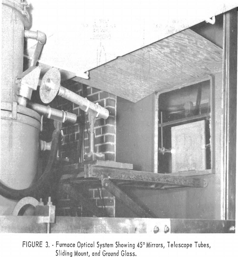
The lens tubes are mounted on a plate, which in turn slides on vee-ways on a steel frame. This feature allows the lens systems to be moved out of the way during furnace charging and unloading, yet permits exact repositioning of the lenses. Figure 3 shows a photograph of the unit.
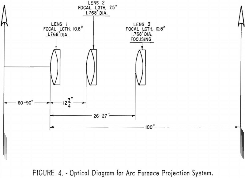
The chief advantages of this three-lens unit are possible wide variability in installation dimensions and small variation required to focus on a changing pool level. A further convenience is that the ground glass can be moved manually to focus rather than moving one of the lenses. Lens movement would require a complex remote-operated mechanism. Figure 4 depicts the optical diagram of the unit.
Alloying Methods
Normally, alloy additions are made to the sponge compact before first melting. Usually, an effort is made to confine the additions to the core of
the briquette to eliminate alloying during welding of the compacts. Double-melted or at least single-melted sponge is used for the final casting electrode to minimize porosity in the product.
An interesting variation practiced recently was the production of a cast alloy by the use of commercial bars of the several ingredients welded together to form the electrode. An alloy of uranium, columbium, and zirconium was produced with reasonable homogeneity by this technique. Similarly, binary alloys with less tendency to segregate have been cast successfully with a laminated electrode.
Mold Materials
The problems of mold materials are inseparable from any discussion of casting techniques. With reactive metals these problems are compounded many times. Common foundry sands are useless, and only materials that are relatively inert and insoluble in the melt can be considered.
Basic requirements for mold material used in casting any metal are (1) the ability to resist attack by the molten metal, (2) a quality of surface finish that will produce a satisfactory casting, and (3) a structure that can be readily broken up when molds are expendable or can have a relatively long life when molds are permanent.
When the reactive-metal casting technique was first satisfactorily developed in 1955, three mold materials were available; namely, machined artificial graphite, rammed powdered graphite, and massive and/or water-colled copper or aluminum. This choice of materials has not yet been extended, although considerable refinement has been achieved, particularly in expendable rammed graphite.
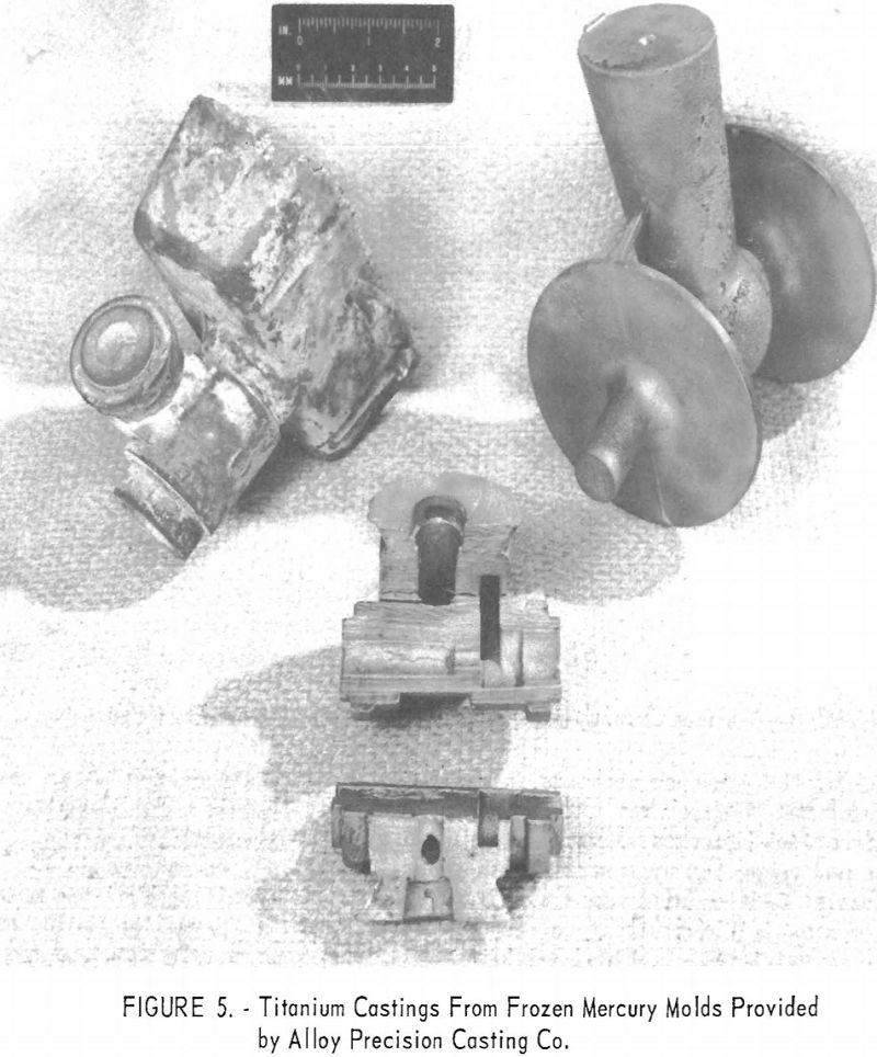
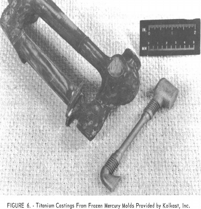
Among the interesting alternate materials tested was zirconium silicate formed into molds by the frozen-mercury investment technique. Figures 5 and 6 indicate that mold reaction is severe except on the thin casting sections. Oxygen contamination on the thin sections was less than 0.03 to 0.04 in. deep.
Choice of mold material for the production of any given casting must be governed by the end use of the casting and by the physical and mechanical specifications to be met. Castings poured into machined graphite molds had an as-cast surface equal or superior to that of the best commercial diecasting, whereas castings produced in expendable or rammed graphitic molds were rough and somewhat discolored. Castings produced in machined graphite generally were lower in carbon contamination and more resistant to corrosion, but were more costly. Where a superior finish or corrosion resistance is not required, expendable graphitic molds provide a more economical method of producing titanium and zirconium castings. Massive and water-cooled metallic molds are useful in producing castings with no surface contamination due to mold reaction, but they are ungainly to handle, costly to produce and generally limited to simple shapes.
Machined Graphite
Dense graphite was an early choice as a mold material for zirconium and titanium casting. The ease with which this material is machined, its reasonable strength, high thermal conductivity, and low reactivity with the molten metal, make graphite suitable for a permanent mold material for many casting applications.
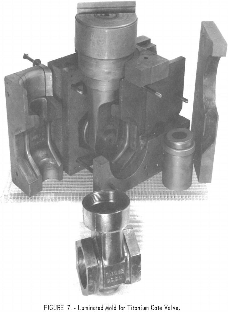
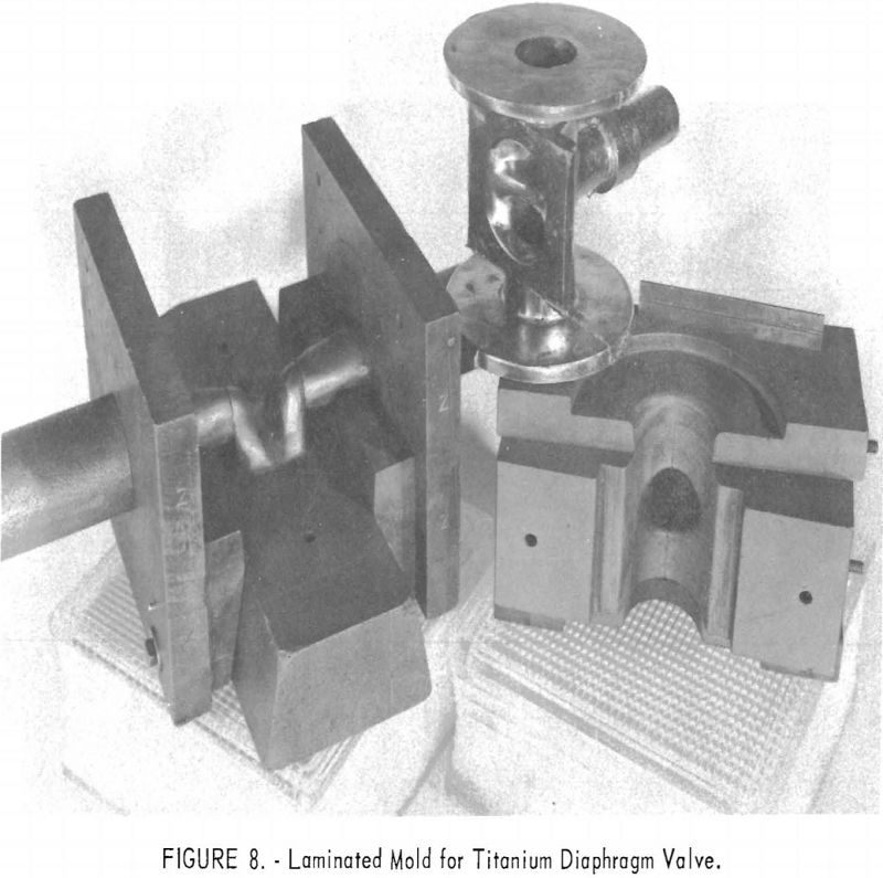
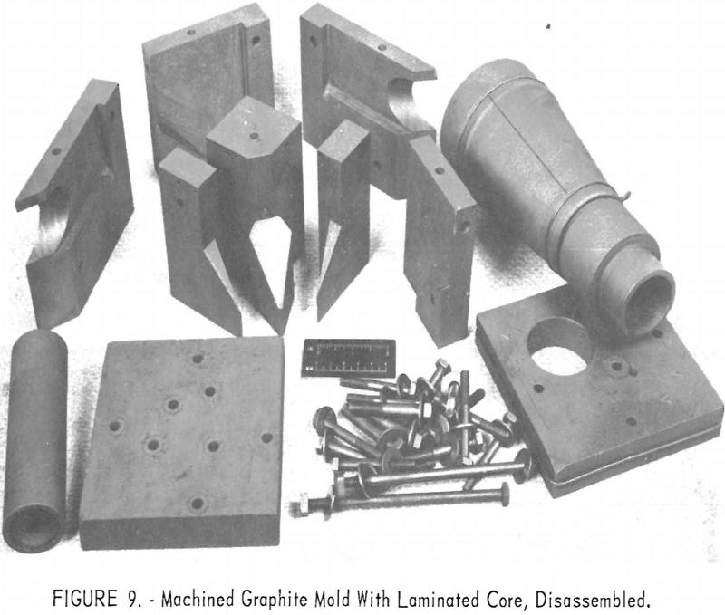
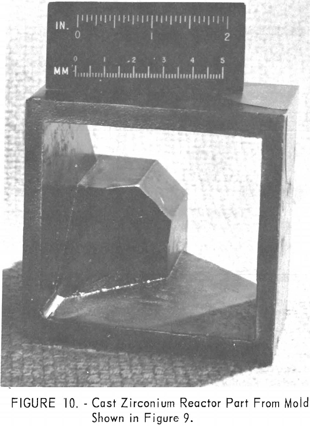
One of the greatest problems in designing machined graphite molds is how to prevent the casting from binding the mold when it shrinks. For example, the conventional flanged valve will have two flat flanges parallel to one another and connected by a straight section. On cooling, the shrinkage of the straight section will cause the flanges to pinch tightly against the mold parts, making it difficult if not impossible to save the “permanent” mold for reuse. To solve this problem, a system of laminar construction with tapered key sections has been worked out. Figures 7 and 8 show typical laminated molds. The laminar construction reduced the breakage and simplified the machining of deep cavities. Cores also can be made of multisection units with a key block, as shown in figure 9. Figure 10 shows the resultant casting.
It is necessary to obtain fine-grain dense graphite, (1.65 g/cc. or more) to realize the best surface finish on the casting. Care in preparing radii and in smoothing mold faces was essential to good castings and good mold life. The Bureau has not had occasion to produce any single part in enough quantity to determine the average mold life of a properly designed unit. However, several patterns have been used 8 to 12 times with negligible deterioration.
Inspection of a casting poured in graphite makes it apparent that the molten metal was in contact with the graphite for only a fraction of a second before it froze and shrank away from the mold surface. In some instances reaction and washing were observed where a heavy flow of metal impinged on a graphite surface.
Rammed Mold Material
Expendable, powdered graphite molds have certain advantages over machined graphite molds. In some instances, material with a lower heat conductivity than machined graphite promotes internal soundness. There is an obvious need for an inexpensive, suitably inert, expendable mold material that can be easily formed with standard foundry equipment. The Bureau recognized this need and made preliminary studies in 1954.
The next step forward in the development of a material of this type was the announcement by Feild in 1956 of a carbonaceous mix capable of being prepared and used in the average commercial foundry. Basically, this mix is composed of electric-furnace graphite powder AFS 80. Binders include common starch for green strength, pulverized pitch, and carbonaceous cement. The
fluid vehicle is water plus a surface active agent. Although the mix and the techniques involved are still undergoing improvement, a basic operating procedure has been established. The best composition was reported to be “53 percent electric-furnace graphite powder (-20, + 100-mesh), 10 percent dry corn starch, 10 percent pulverized pitch, 8 percent carbonaceous cement, 1 percent surface-active agent (Dupanol G, a fatty alcohol amine sulfate) and 18 percent water.” The foregoing mold material has been evaluated, and at least one commercial producer of titanium castings is using this form of expendable mold.
A new program for developing and evaluating expendable carbonaceous molds was begun by the Bureau in 1957. Considering the approach used by Feild and after evaluating the cited material on the basis of casting quality, the Bureau decided to attempt the production of a carbonaceous mold mix completely devoid of free water or water-containing materials.
Surface contamination of a casting caused by its reaction with a given mold material is partly dependent on the solidification rate. This in turn is a function of the thermal conductivity of the mold, a factor of which is
the mold density. The condition of the mold faces is also a factor governing mold-metal reaction. A rough, soft surface tends to “wash”, and any corners or prominent projections may be completely eroded.
The internal soundness of a casting also is affected by the thermal conductivity of the mold material. When a material such as machined graphite is used, surface laps or flowlines, internal shrink pockets, and possibly, some gas entrapment may result because of the lack of permeability and the comparatively high thermal conductivity of the mold material. In most instances these can be controlled adequately by proper gating and risering, and are not serious deterrents to the use of machined graphite. However, thermal conductivity and permeability are factors that must be compromised to form castings, having little or no surface contamination, surface laps, or internal porosity.
The mold material developed by the Bureau and the process for its production are still undergoing evaluation, and some alteration of formula and process is expected. A complete report covering this material will be published later. Presently, however, the blend is composed of powdered graphite, linseed oil, and wax combined with one or more of the following ingredients: Cornstarch, cereal binder, dextrine, powdered sugar, and powdered pitch.
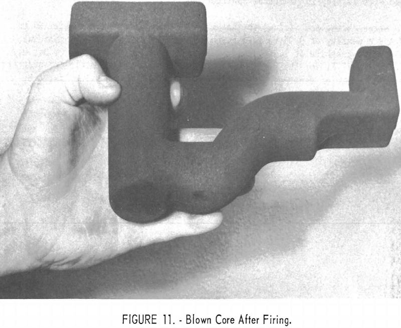
The dry ingredients are blended in a double-cone-type blender. The lin-seed oil and wax, heated to “stand” temperature (permit partial polymerization), are added to the blend, and the mass is thoroughly mixed in a ribbon mixer. The resultant blend may be hand-rammed, blown, or otherwise treated as in standard sand-molding practices. Figure 11 shows an expendable graphite core produced on a commercial core blower from the material being developed and evaluated by the Bureau.
After being rammed, the mold is stripped and then aged at room temperature. This aging time, which varies from 12 to 72 hr., depending on mold or core dimensions, allows the oil and wax mixture to “stand” or partly polymerize, thus giving the green mold adequate strength for handling.
A low temperature drying cycle is necessary before firing. The assumption is that drying at 200° F. for 48 to 120 hr. facilitates the removal of volatiles. If this low-temperature drying cycle is omitted, the sudden evolution of volatiles during the high temperature firing (up to 960° C.) causes the mold or core to be distorted and to become porous or, in some instances, to disintegrate completely.
After treatment at 200° F., the material is adequately hard but still contains enough volatile materials to cause excessive gas in the mold; there¬fore, more complete carbonization is necessary. This is accomplished by placing the mold and heating it in an electric furnace, in a reducing atmosphere, elevating the temperature to a maximum of 960° C. This temperature is maintained for ½ to 1 hr. The mold is allowed to remain in the furnace during the cool-down period to prevent oxidation.
The reducing atmosphere in the electric furnace is provided by embedding the core or mold in commercial pulverized coke in a covered stainless steel container. In some instances, adequate protection is achieved by omitting the coke bed and merely sealing the steel box with a graphite cover. Bedding is useful for molds or cores susceptible to distortion.
The decision to limit the time and temperature to the values shown is strictly arbitrary. Earlier work showed benefits in using temperatures up to 2,000° C. and long time cycles. Vacuum firing would also be an improvement; however, temperatures above 1,000° C. and reduced pressures are not easily obtained in commercial equipment, and time is a factor that must be compromised with quality in practical application.
After curing and firing, the material had a hardness of Durometer 95 to 100 and a density of 0.95 to 1.28 g./cm.³, compared with that of commercial dense-grade graphite of 1.7 g./cm,³. The thermal conductivity was 20 B.t.u./ in./ft.²/hr./° F. for the rammed material, which was approximately one-quarter that of commercial dense-grade graphite and up to twice the value listed by Frankford Arsenal for their rammed mix.
Whenever practical for a given configuration, the technique of core-blowing has advantages over handramming. Use of a core-blowing machine and blow-box molds increases the production rate and efficiency, and, considering permeability and density, produces a superior core.
Centrifugal Casting
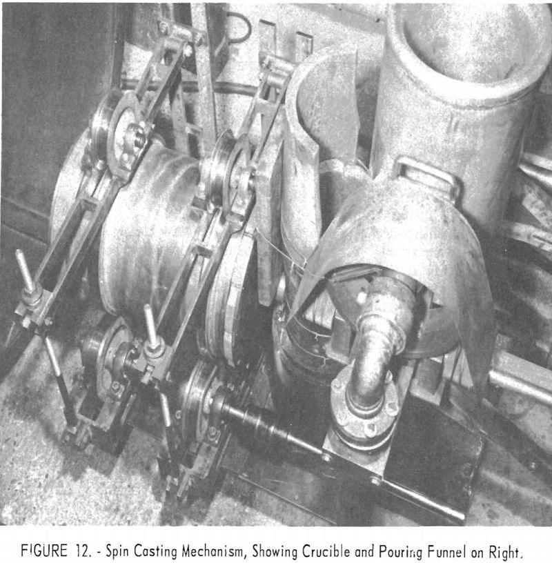
Cast tubes of reactive metals have been produced by centrifugal casting using conventional practice. Figure 12 is a picture of the inside of the furnace shown in figure 1. The spin-casting apparatus consists of a duplicate set of three spindles: The top one is spring loaded, driven by a jackshaft and chain; the shaft passes through a vacuum gland in the furnace wall. Molten metal is poured into a graphite cylindrical mold backed by a steel pipe. Hardened steel rings, which match the trunnion wheels and prevent lateral drifting, are mounted on the exterior of the pipe. The ends of the casting mold are also graphite with steel backing. The trunnions are mounted so that their spacing can be adjusted to fit molds 4 to 18 in. in diameter, and the chain drive permits lateral adjustment.
In operation the metal was poured through a large funnel into a vertically placed graphite tube. The metal flowed into the mold through a 1-½-in.-diameter sprue. Speeds of 400 to 1,200 r.p.m. have been used, resulting in centrifugal forces on the order of 70 to 100 G’s. Figure 13 shows some of the castings produced from a titanium alloy and one of the molds disassembled.
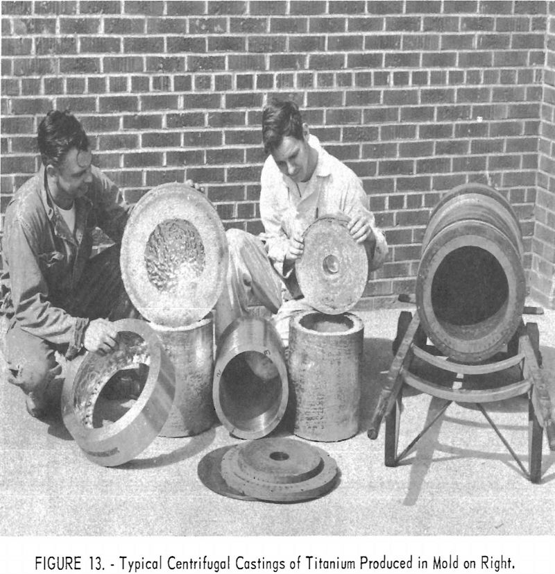
The apparent surface contamination due to graphite is very slight. This suggests again that the metal was in contact with the mold walls for only a short time before it froze and shrank away. Of interest was the relatively fine-grain structure of these castings, compared with the large grains in the conventional cold-mold ingot. The surface finish on the interior was usually of excellent quality, except in instances where very short castings were made. It is presumed that this roughness was due to excessive turbulence during pouring.
Originally, porosity was evident in some castings. This has been eliminated to a large extent by the use of good-grade melting stock and by more careful control of energy input. As an example of the soundness obtained, two cylindrical castings of hafnium, 12 in. long by 1-½ in. ID by 2-¾ in. OD, were gamma-graphed by another agency, which reported an area of sponginess near the end of one casting and a few spots of porosity near the exterior surface, the largest being about 1/16-in. in diameter.
In commercial extrusion practice, zirconium and titanium arc-melted ingots must be forged to break up the gross grain structure. For tube production, then, sponge must be double melted, conditioned, forged, conditioned, and bored or pierced. As an alternative, the proposal was to double melt, spin cast, and machine to final size, eliminating two steps and improving the yield. Another advantage can be realized when the cost of drilling or boring becomes prohibitive because of hardness of the alloy.
Three Zircaloy-2 blanks were produced during 1957 and shipped to Chase Brass and Copper Co. for extrusion. All outside surfaces of one tube were left in the as-cast condition; the surfaces of the remaining two tubes were conditioned by machining.
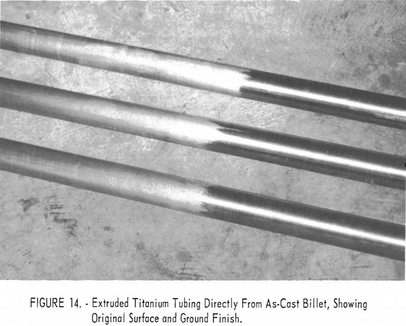
From original dimensions of 6.73 in. OD by 1.82 in. ID by approximately 9 in., each blank was successfully extruded to tubes of 2-1/16 in. OD by 1-5/8 in. ID by about 17 ft. long. Results for the blank with as-cast surfaces were particularly pleasing, perhaps because an inferior product was anticipated. Actually, all tubes produced appeared to be satisfactory, and only a relatively light finish grinding was required. Figure 14 shows the tubes with part of each still in as-extruded condition and the remainder as-ground. Table 1 shows the material yield.

Extrusion was followed by a group of bench-drawing and stretch-straightening tests. The following items summarize the results of the test:
- Centrifugally cast blanks of Zircaloy-2 can be successfully extruded directly from the as-cast state without intermediate conditioning other than light machining of surfaces.
- The outside surfaces of extruded tubes are commensurate with the surface finish of the starting blanks but otherwise are normal for Zircaloy-2.
- Extrusion without prior machining of cast surfaces results in unexplained surface stringers but is otherwise satisfactory.
- The inside surfaces of extruded tubes are somewhat rougher than normally expected for Zircaloy-2 but are still acceptable.
- Extrusion can be followed by bench drawing to achieve additional reduction in area up to a total of at least 25 pct. in about 10- or 15-pct. increments. Vacuum annealing, recoating, and maintenance of small plug clearances may permit reductions in area by drawing up to a total of about 50 pct., but this possibility must be tested further.
- Relatively slight stretching of extruded Zircaloy-2 tubes results in a significant increase of 0.2 pct. offset yield strength without comparable changes of other tensile properties.
Physical Properties of Cast Material
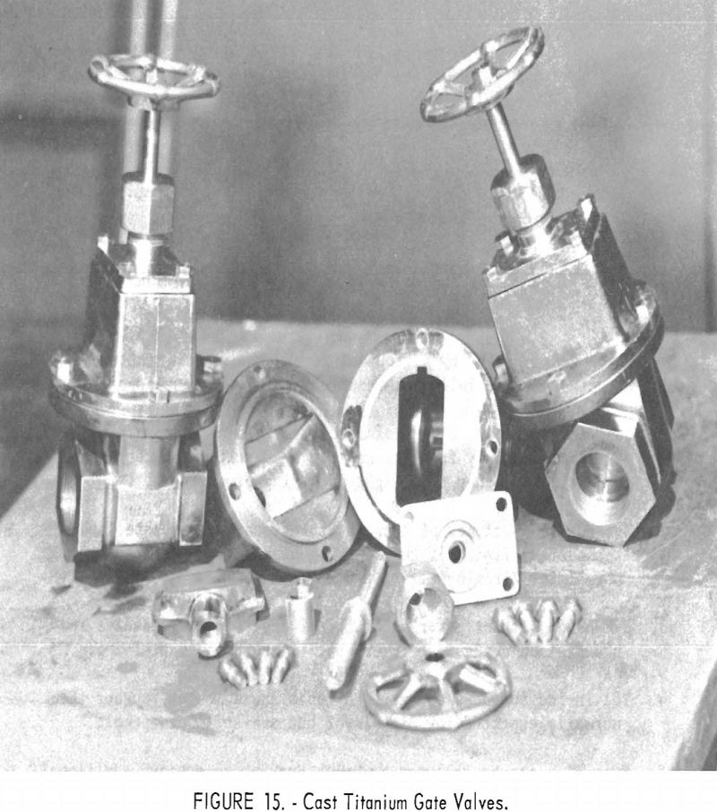
In October 1957 a series of the gate valves shown in figure 15 was placed in industrial service to establish performance characteristics when subjected to (a) water containing 2,300 p.p.m. chloride at 284° F. (140° C.), (b) 65 pct. nitric acid at 230° F. (110° C.), (c) 15 to 16 pct. sodium hypochlorite at 194° F. (90° C.). The same valves were hydraulically tested, and all seats and gasket seals withstood at least 500 p.s.i. of sustained pressure. This was the upper limit of the hydraulic testing equipment. After 1 yr. of operation as specified above, the valves appear to be unchanged.
A group of 25 Zircaloy-2 brackets of the type shown in figure 10 was fairly typical of static castings produced in machined graphite molds. A discussion of their properties will be used to illustrate the normal quality to be expected in reactive metal castings. Surfaces were generally smooth, but there were occasional superficial folds or wrinkles caused by the high rate of heat loss to the graphite mold. The surfaces ranged from bright to light shades of tan or grey. Metallography of surface sections revealed that carbon contamination extended to a maximum depth of 20 mils (0.020 in.). Analysis of samples collected from the first 5 mils under the surface indicated 400 to 600 p.p.m. carbon, and analysis of samples from the entire 20 mils of surface contamination indicated 200 to 400 p.p.m. carbon. Above 500 p.p.m., carbon contamination causes a slight increase in the corrosion rate of zirconium in chloride solutions, but this increase does not become serious until the contamination level exceeds 1,000 p.p.m.
Internally, the bracket castings contained scattered porosity, mostly pinhole variety; but in a few instances porosity approached 1/8 in. The soundness was adequate for normal corrosion service but would fail to meet the usual aircraft-type specifications. However, there is no reason to believe that aircraft quality could not be obtained through the improved design of static molds or by resorting to centrifugal casting techniques. In 1959 the Air Force was sponsoring research in several phases of this problem.
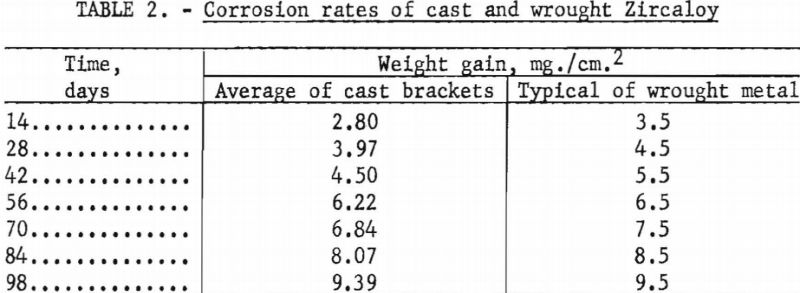
Several brackets were subjected in their entirety to corrosion by steam at 750° F. and 1,500 p.s.i. for 3 days. The result was a normal lustrous black oxide layer. No white corrosion products were formed. Standard corrosion coupons were also collected and subjected to 750° F. steam at 1,500 p.s.i. for a total of 98 days. The results are compared in table 2 with typical behavior of wrought metal.
The average 0.2 pct. yield strength was 49,600 p.s.i., average tensile strength 66,600 p.s.i., and reduction in area at the fracture averaged 36 pct. These values are typical of hot-rolled metal of the same composition. The thin wall sections of the cast brackets necessitated a substandard Charpy V-notch test, and a special series of specimens from wrought metal was tested for comparison. The cast specimens possessed about one-half (6 ft.-lb.) the impact resistance of wrought metal (10 ft.-lb.) both at room temperature and at 200° F. Testing of the cast brackets was performed by the Atomic Power Division of Westinghouse Electric Co.
Process Variables
Largely as a result of intuition, practical casting techniques have been developed, but there are several areas of potential improvement. The need has been shown for further development of mold designs and materials or other changes leading to reduced costs, improved casting soundness, and a wider range of process application. Also, the use of a vacuum techniques has not been fully exploited for maximum improvement of product quality. Progress toward these objectives is continuing, but there is a real need for a clearer understanding of process control and the influence of various operating parameters. Of special interest are variations in the yield of metal (percent of charge poured), the distribution of heat, metal temperatures, and melting rates as functions of arc current, pressure, alloy composition, and casting sizes.
The Bureau has conducted two separate series of zirconium casting heats to study the influence of electrode diameter on the yield of metal. The first series consisted of three heats, all without benefit of initial skulls, in a 9-½-in.-diameter ladle, at nominal currents of 8,000 a., and at nominal pressures of 100 to 200 µ. The only deliberate variable between heats was the electrode diameter. As an extra precaution, all electrodes were fabricated from the same ingot stock to minimize variation of metal composition. Table 3 shows the results. A second series of three heats followed using the same procedure, except that the ladle was 8-½ in. in diameter, pressures were more nearly 400 µ. and the electrode sizes were smaller. Table 4 tabulates the results. The variation of the yields in each series has no significant order in relation to electrode size. The minor differences observed are no more than might be expected to result from such things as cooling irregularities. However it is not standard practice to generate a new skull in each heat, as was done in the experiments. Accordingly, a conclusion that electrode size has no bearing on yield must be qualified by the admission that when a skull is retained through a series of successive heats its weight usually increases slightly to some equilibrium value over the first several melts. This weight increase is principally a buildup at the upper rim of the skull, and it is suspected that the ultimate buildup is greater for smaller electrodes.


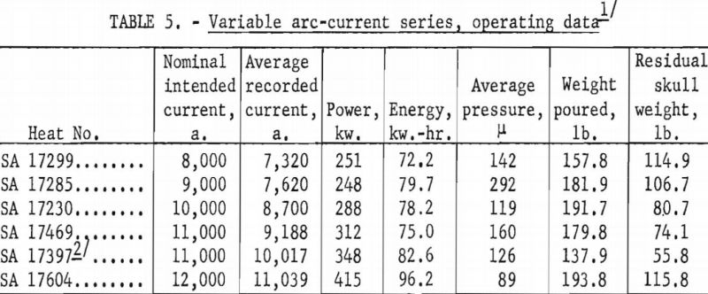
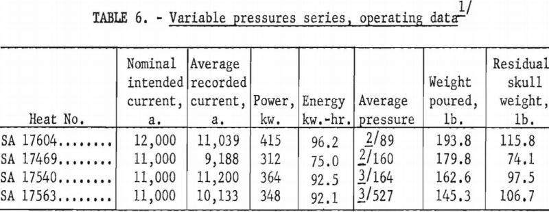
A larger series of experimental heats with titanium alloys furnished information on yields, metal temperatures, melting rates, and mold reactions. This series included six levels of arc current, three distinct ranges of pressure, three ladle sizes, and four alloy compositions. Each of the various water-cooling loops associated with the casting furnace was equipped with a flowmeter and iron constantan thermocouples for continuous recording of coolant volume and temperature. These data were used to calculate the relative distribution of heat to the various furnace components as a function of time. Strip-chart records of current, potential and time supplied a total energy input figure for each heat, and this was proportioned and assigned in accordance with the heat distribution derived from the volume and temperature of cooling water. Average molar heat contents and metal temperatures were deduced from the partition of energy between the molten and solid portions of the charge. As standard practice, weights were obtained that allowed the calculation of metal yields and average melting rates. Each pour was made into a network of cubical mold cavities ranging in size from 1 to 8 in. Most molds were of machined graphite, but in several instances sizes up to 4 in. were duplicated with mold components of rammed graphite furnished by Frankford Arsenal. Thus, direct comparison was possible between the various sizes and between the two mold materials. Rammed mold materials are being constantly improved and the relevant results of this study typify only the rammed materials available in June 1957. Operating data are summarized in tables 5, 6, 7, and 8.
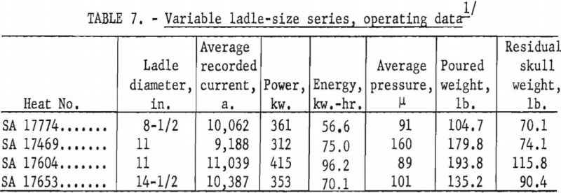
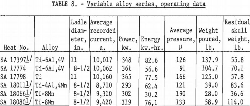
The choice of method for temperature estimation may be criticized, but the method was selected because the temperatures are too high for conventional probe measurements, and optical or radiation pyrometry is complicated by ionized vapors and reflection of an electrode image from the molten pool surface. In addition, investigators decided that an average temperature has more significance than a localized temperature.
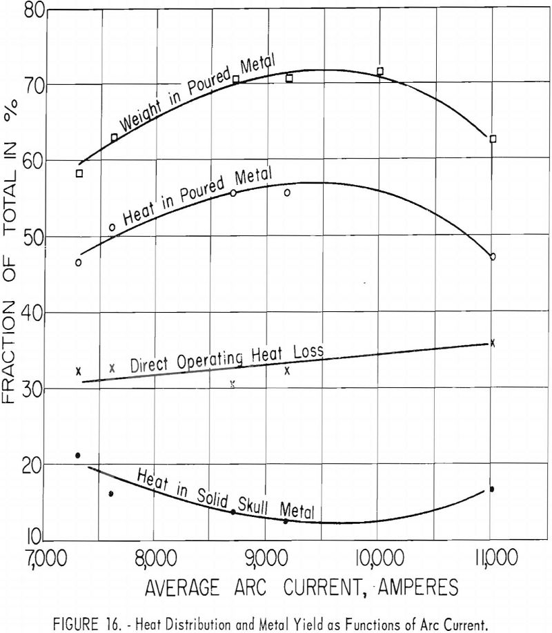
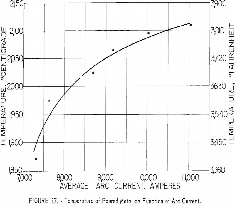
Figures 16 and 17 present some effects of arc-current variation. These graphs are associated with the operating data of table 5. Although the efficiency of operation reached a maximum at some optimum current near 10,000 a., the temperature of the molten metal continued to increase at higher currents.
Arc current is also a major factor in determining melting rates. That the melting rate is directly proportional to arc current has been recognized by those who engage in d. c. arc welding with a consumable rod and in production of simple ingots by consumable electrode arc melting. This is also true of consumable electrode arc casting, but care must be exercised in defining melting rate. In arc melting ingots, where a skull is not formed, the melting rate is the same as the rate of electrode consumption. Skulls are involved in arc casting, and researchers found that any loss of weight by a skull must be added to electrode consumption to yield a melting rate proportional to arc current. If a skull gains weight, the increase represents metal acquired from the electrode and is already included in the electrode consumption rate. The ratio of melting rate to current in the experiments under discussion was about 1.2 lb./min./k.-a. No ordered dependence of melting rates, temperatures, or operating efficiencies on arc power were discovered. The influence of current was independent of electrical potential.
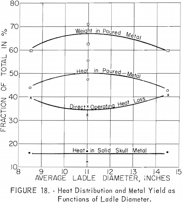
Ladles of different sizes were used with results shown in figures 18 and 19. The diameter of each ladle was 1 in. smaller at the bottom than at the top. The resulting taper facilitated removal of residual skulls but necessitates the use of an average diameter as an index of size. The scatter of data corresponding to the 11-in. ladle size is disturbing at first glance, but more detailed inspection reveals that the spread of values reflects the effect of uncontrollable arc-current variations. Since the ladle size can be fixed rigidly, the scatter did not appear in figures 16 and 17, but since arc current cannot be precisely controlled, its variation must be taken into account in evaluating figures 18 and 19. Within the range of conditions specified by tables 5, 6, and 7, the relation between current and ladle size with regard to molten-metal temperature can be expressed by the empirical quadratic approximation:
T = 430 (1 + 0.51 I – 0.231 I²) (1 + 0.0655 d – 0.003367 d²),
where T is average temperature in °C., I is arc current in kilo-amperes, and d is the mean ladle diameter in inches. A variety of other empirical approximations could have been used. The agreement between values as calculated above and the calorimetrically measured temperatures are shown in table 9. The most serious disagreements occur at currents below 8,000 a. and high pressures.
Attempts to approximate metal yields with equations of similar form have been unsuccessful. Unfortunately, the nature of the relationship between arc current and ladle diameter is more complex when yields are considered, and it
appears that a logarithmic or exponential term may be involved. In any case, the utility of such empirical approximations is limited. There is a real need for a practical, but simplified model of the molten pool during arc melting that will allow a theoretical deduction of equations for temperature and volume.
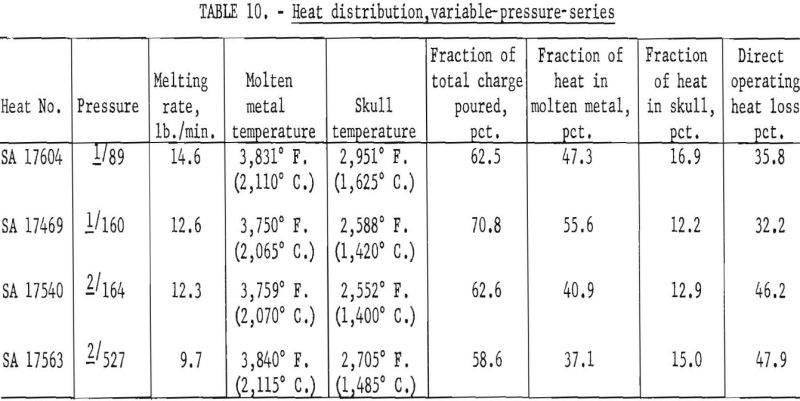
On the basis of earlier studies there is little doubt that furnace pressure constitutes a third interacting variable, but variable-pressure-series results as shown in table 10 indicate that the effect is subordinate to the influence of current and ladle size and less significant than the estimated error of temperature measurement. Thus, to define the role of pressure, more precise methods of arc-current control and of temperature measurement would have to be devised.
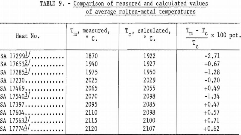
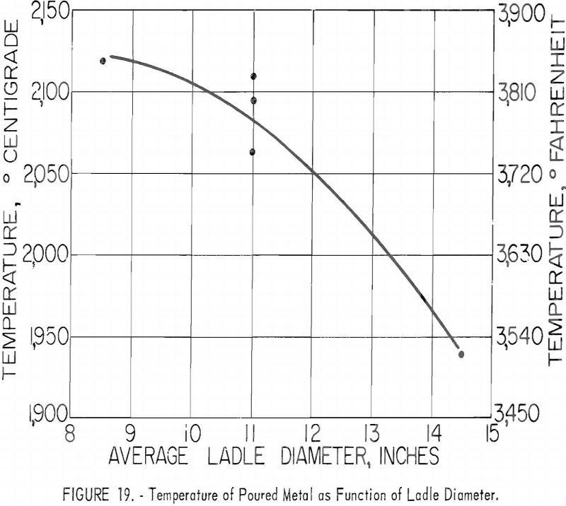
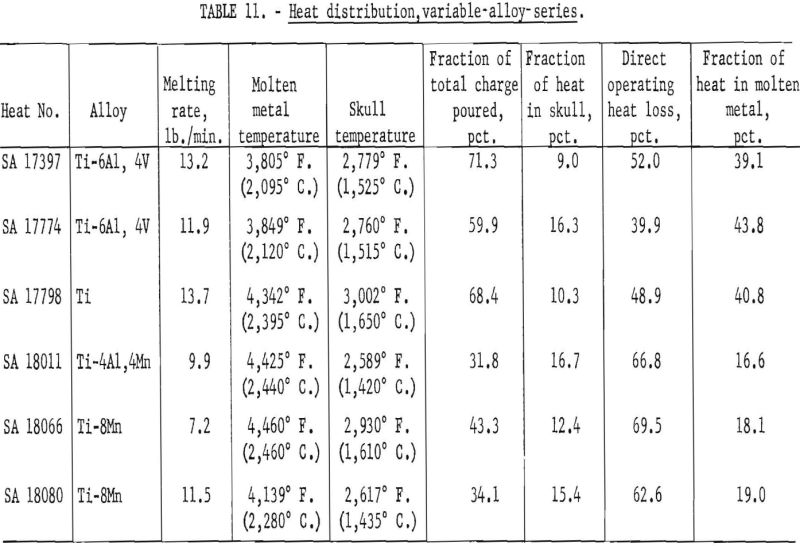
Table 11 compares results for the various alloys that were available. Probably the most significant facts that may be inferred from these data are that molten-metal temperatures were generally higher and operating efficiencies were lower for alloys containing manganese. On the basis of previous routine experience, the lower efficiencies were expected, but investigators had assumed that this was caused by an excessive loss of heat by vaporization of manganese. The existence of higher temperatures and the pressure levels maintained (see table 8) completely contradict this notion. Instead, it now appears that the explanation of lower efficiencies for manganese alloys goes much deeper and involves a basic influence of manganese on the arc-discharge mechanisms, whereby the heat directly received by the arc cathode decreases and that received directly by the anode (in this instance the molten pool) increases.
The temperature of skull metal was remarkably uniform throughout, regardless of operating conditions. Variations were random and could not be related to operating conditions. Values ranged from 2,523° F. to 3,002° F. (1,385° C. to 1,650° C.), and averaged 2,731° F. (1,500° C.). The one 3,002° F. (1,650° C.) value was obtained with commercially pure titanium and is probably too high since the melting point is only 3,020 °F (1,660° C). The estimated error for all reported metal temperatures is ±90° F. (±50° C.).
The similarity between the fraction of the total charge poured and the fraction of total heat contained by molten metal may be noted in figures 16 and 18. Although the similarity seems perfectly logical, it could not be anticipated. The heat content of molten metal certainly must depend to some extent on the volume or mass of molten metal, but not necessarily on the fraction of total charge represented by that mass.
The heat lost during arc operation and not appearing in either cast metal or the residual skull varied widely from about 30 to 70 pct. of the total heat input. The manner in which direct heat losses were dissipated was fairly consistent, however. Of this direct loss, 80 to 88 pct. was included in the heat content of cooling water from the ladle. Another 10 to 20 pct. represented heat generated in water-cooled electrode components, including friction brushes used to apply power to the stinger shaft. Less than 1 pet. appeared as miscellaneous losses through furnace walls.
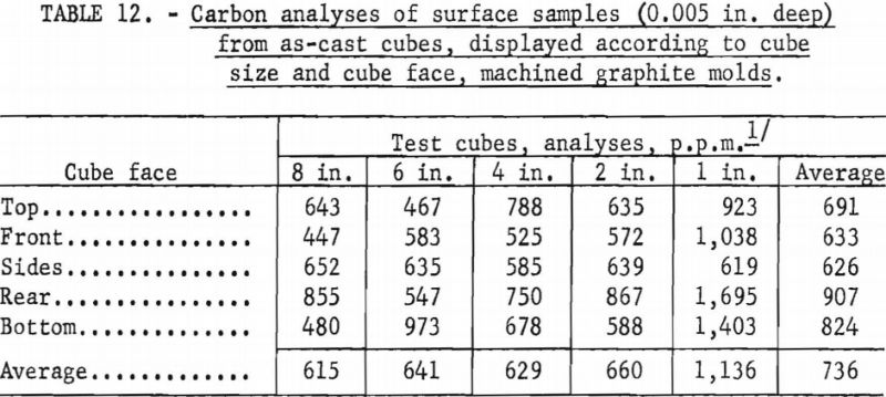
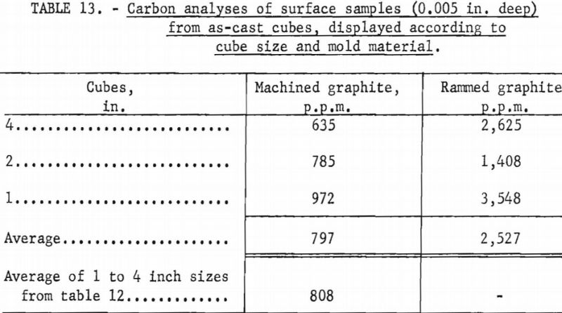
Unfortunately, complete evaluation of the castings produced as part of the experimentation described above is laborious and time consuming. Consequently, full information is not yet available, but results of a cursory analysis of reactions between molten metal and graphite molds appear in tables 12 and 13. The terminology used to designate cube faces in table 12 is as follows: Rear the cube face through which metal was gated into the cube; front-cube face opposite the rear; top, bottom, sides-used in the normal sense and self explanatory. No ordered correlations were detectable between the degree of mold reaction and the various operating variables that influenced metal temperatures, so cubes cast under a variety of operating conditions were grouped for the purpose of the tabulations. The only clear implication to be drawn from table 12 is that the 1-in. molds were more susceptible to attack by molten metal than the larger sizes. Researchers believe this is a consequence of a washing action accentuated by the small dimensions. In larger molds the force of metal flowing in is dissipated over surface areas that are larger and more remote from the point of metal entry. Table 13 shows that the surfaces of cubes cast in rammed graphite molds are sufficiently contaminated to have low corrosion resistance. However, sand blasting and pickling of such castings should readily expose corrosion-resistant metal. Typical analyses for carbon in the melting stock used to produce the cubes were between 100 and 200 p.p.m.
