Table of Contents
- Loss of metal and damage to buried metal structures because of corrosive action is, to a large extent, determined by the soil resistivity in the immediate vicinity of the structure. The intensity of corrosive action is inversely proportional to the soil resistivity; that is, corrosive action will increase as the soil resistivity is lowered.
- Moisture is one of the main factors that affect soil resistivity. It also affects the resistivity with respect to earth of grounding mediums. If the moisture content of the soil surrounding a grounding medium varies seasonably, it will tend to make the resistivity with respect to earth of that medium fluctuate.
- Multiple grounding rods or integration of two or more grounding mediums is desirable to reduce resistivity fluctuations and provide lower ohmic values.
- Integration of all metal structures and provision of a good power return for direct-current systems will tend to minimize circulating currents and reduce damage to equipment. Where circulating currents should be eliminated, insulating couplings can be used to advantage.
- Cathodic protection can be used to mitigate corrosion of buried structures or provide spot protection from corrosive action for surface structures. Such protection can (in many instances) be used with a well-designed protective grounding system.
- Corrosion-prevention programs using cathodic protection principles can be used advantageously in many mining installations. On the other hand, cathodic protection systems requiring heavy currents would not be desirable in mines where explosion or other hazards would be introduced if ground circulating currents are introduced.
Grounding of electrical equipment and metal structures for the purposes of protecting personnel from shock hazards, preventing damage to equipment, and minimizing property loss has been generally accepted by industry. Nevertheless, grounding as a safety measure has become a most controversial subject because of the varying opinions among supervisory, operating, and engineering personnel. Most differences do not appear to stem from questioning the desirability or feasibility of grounding as a safety measure but rather from disagreement on the system or, more often, the mediums to be used. Generally speaking, electrical grounding has been accepted as a safety measure and is practiced in various forms to various degrees in mining, manufacturing, petroleum and its related industries, and electrical utilities.
Although company and safety-code requirements for grounding vary for each industry, the basic principles are the same. Electrical grounding systems are designed to provide a path for fault currents to earth, to a given grounding medium, or to provide means for neutralizing electrostatic charges, which equalize differences in potential levels with reference to ground or reference levels. For the types considered in this discussion, the earth is the usual grounding medium; soil conditions adequate for grounding requirements are of primary importance.
It should be pointed out, however, that the very requirements that make a grounding system or medium satisfactory, from the standpoint of shock hazards, such as conductivity and ability to absorb or dissipate static charges or stray electric currents, may be the most detrimental factors when corrosion is considered. The earth’s properties as a grounding medium and grounding systems in general are obviously integral parts of corrosion prevention.
Underground corrosion has too often been taken for granted. In many instances preventive measures have been delayed until considerable damage has resulted. In effect, corrosive action is the tendency of refined metals to revert to their original forms as ores or compounds, thus reaching a state that is most stable under given conditions. This action can be detected by the presence of chemical action or flow of electric current from the metal to the surrounding medium. Since chemical actions usually set up potential differences, a flow of current would be induced by such actions; conversely, a flow of current between dissimilar substances results in chemical action. Consequently, the flow of electric current plays a major role in corrosive action and resultant damage. Cathodic protection is basically the technique of providing a flow of current in an opposite direction to the flow of current induced by natural corrosion, thus mitigating or totally abating the action of natural corrosion.
Soil Resistivity
The surface of the earth is composed of various materials, which differ sharply in their ability to conduct electric current. Because of this widely different electrical conductivity or ability to resist the passage of electric currents, the so-called resistivity varies not only locally in different sections of the country but also in depth from the surface. Several factors, such as moisture, composition, and texture, affect soil resistivity; moisture is perhaps the most decisive.
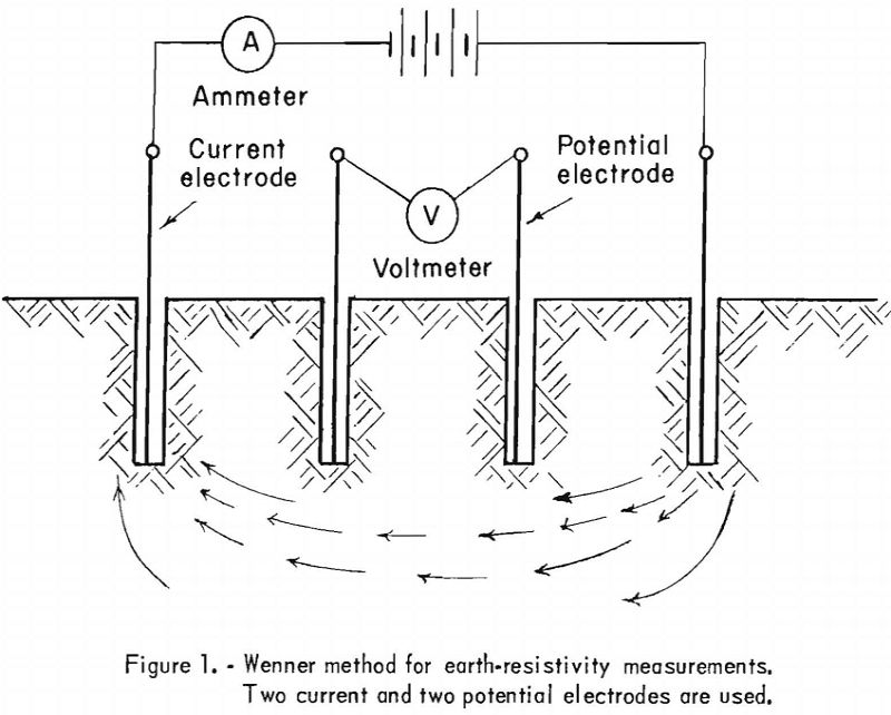
Various methods and instruments are used to determine soil resistivity, which is usually expressed in ohm-centimeters (ohm-cm.); an ohm-centimeter, essentially a unit of volume resistivity, is the resistance, in ohms, of a unit conductor having a cross-sectional area of 1 square centimeter and 1 centimeter in length. The Wenner method for measuring earth resistivity, developed in 1915, is usually employed. This method, as originally developed, utilizes four electrodes placed in holes on a straight line. The electrodes are spaced evenly and placed at approximately the same depth in the holes, making contact with the soil only at the bottom of the holes. Two electrodes (the outer pair, for instance) may be used as current electrodes and the other two as potential electrodes (see fig. 1). Soil resistivity can be calculated from the distance between electrodes and the measured resistance.
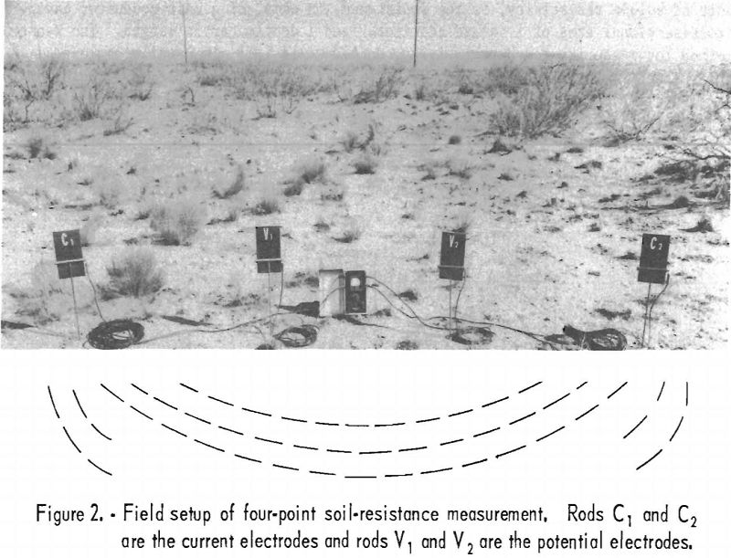
A typical field setup of a four-point method for measuring soil resistance is shown in figure 2. This method is a variation of the Wenner method, using 125- volt, 97-cycle current to eliminate interference. The depth of average soil resistivity measured is determined by the spacing between the reference rods, but the depth of the rods in the ground does not enter into the calculations. The electrodes used are copper pins inserted in the ground. It is unnecessary for them to make contact at the bottom of the holes only, as in the original method.
Data on soil resistivity not only are important in the design of cathodic protection systems but, in the opinion of some corrosion engineers, may be used as an index of corrosion severity. For example, areas having soil resistivity under 900 ohm-cm. are considered to produce very severe corrosion; soils with 2,000 to 5,000 ohm-cm. resistivity can be classed as moderately corrosive; and those of over 5,000 ohm-cm. resistivity usually are mildly corrosive.
Generally speaking, the soil electrical resistivity decreases with depth; this unit-volume-resistance decrease, as previously mentioned, is normally due to moisture content. Some localities show a marked decrease: Boston, Mass., averages 60,000 ohm-cm. from 2 to 6 feet and about 7,000 ohm-cm. from 8- to 12-foot depths; New Orleans, La., shows soil resistivity of 800 to 350 ohm-cm.; Denver, Colo., is within the 3,000- to 1,200-ohm-cm. range in the 2- to 12-foot depth
Regardless of the wide resistivity limits within which the materials composing the earth’s crust fall, relatively speaking the earth does not offer a prohibitive resistance to the passage of electric current. Therefore, the earth is often used advantageously as a return conductor for electrical grounding systems and communication systems and for cathodic protection. The earth’s property of conducting electric current can be misused, however, when it is utilized as a power-return conductor in operating equipment. An example of such misuse was the power-distribution system in a small coal mine, where single-phase, 110-volt, alternating-current power was provided for lighting and operating handheld drills by connecting 1 conductor to the 220-volt power-feeder line and the other conductor to the earth.
This was made possible because of the grounded center tap on one of the main distribution transformers on the surface. Ground connections were made through a ground rod and the frame of a car-spotting hoist situated at a wet loaderhead. No continuous power-return conductor was provided to the surface transformer. Such a practice is unquestionably dangerous, not only because of the shock hazard that it introduces but also because of possible damage to equipment and inefficient operation of the electrical apparatus.
Ground-Resistance Measurements
When the subject of protective grounding is discussed, the term “effective grounding” is often used. This is a general term; when referring to protection from shock for personnel, it means establishment of a low-resistance path to earth that will have enough carrying capacity to make the safety overload-protective devices operative in case of a fault and to prevent establishment of unsafe potentials. The National Electric Code sets up requirements for effective grounding, as follows:
The path to ground from circuits, equipment, or conductor enclosures shall be permanent and continuous and shall have ample carrying capacity to conduct safely any currents liable to be imposed on it, and shall have impedance sufficiently low to limit the potential above ground, and to facilitate the operation of the overcurrent devices in the circuit.
These requirements refer to normal grounding for shock protection of personnel from equipment or parts of equipment that may become “alive” through contact with electric circuits or energized parts. They are not intended to cover grounding as applied to reducing or eliminating hazards caused by electrostatic charges. In hospital operating rooms and other hazardous places, grounding to neutralize electrostatic charges is accomplished through conductive wheels or tips; relatively high resistances are permitted in the neutralizing circuits. For instance, maximum values of resistances in charge-neutralizing circuits up to 500,000 ohms are considered acceptable; this is the safe upper limit recommended for conductive floors in hospital operating rooms by the National Fire Protection Association and the Government Committee on Explosions in Hospital Operating Suites. Other recommended maximum resistances are 250,000 ohms for shoes of operating-room personnel and 250,000 ohms for single leg tips, tires, or coasters of equipment. In such equipment, when 4 points of contact in parallel are considered, the resistance would be 62,500 ohms. Those values are for conductive contacts to floors for neutralizing static charges and should not be confused with the minimum requirement of 25,000 ohms between the floor and ground or between 2 electrodes placed 3 feet apart on the floor for minimizing shock hazards from possible defects in electrical equipment.
In industry it is generally desirable to establish a grounding medium that has less than 3.0 ohms resistivity with reference to earth when shock hazards are considered; however, grounding lightning arresters to rods having a resistivity up to 25 ohms is acceptable.
The foregoing discussion makes it obvious that, in grounding systems, the grounding medium plays an important role. If such a medium is to be effective, it should be able to provide for the system a resistance to ground, within the required range, that will not fluctuate beyond predetermined limits. It is evident, therefore, that the stability of the grounding medium is the main factor that determines its suitability.
As pointed out previously, the moisture content in the soil determines the degree of its resistivity; similarly, it was reasoned that moisture in the soil would affect the resistivity with reference to earth of the grounding mediums. In order that a better picture may be obtained of the degree of such fluctuations, if any, Bird and Smith conducted extensive studies at various California oil-field installations. The tests were made during the normally wet season in March and April and in the dry season in August. Tables 1 through 9 give the data obtained. Two separate sets of tests were made at the same locations, and test setups and conditions were duplicated as nearly as possible. Tables 1, 3, 7, and 9 on well derricks show a definite and consistent increase in the resistivity during the dry season. It should be pointed out that the resistivity of only one well, Hartman No. 16 (table 7), did not increase during the dry season. The adobe-type soil at the location of this well was apparently able to retain moisture. Most wells increased 300 percent in resistivity during the dry season, and well 6-16Q (table 3) increased 3,700 percent.
It is interesting to observe that the tank installations did not show any appreciable increase in resistivity and in some instances showed a decrease. Nevertheless, these data in table 2 cannot be considered as indicative of a trend, because the tanks had been rebuilt between tests. An inconsistency was noted during the tests; the Taylor No. 7 tanks in the river bottom showed an increase, but the rest of the farms showed a decrease, even though the Taylor No. 18 farm was on a hill.
The data obtained definitely show that moisture contributed to the lowered resistivity and the establishment of a better ground contact between the grounding mediums and earth; they also show that individual grounding rods or independent systems are not as effective as systems of several interconnected components. This second conclusion is consistent with Bureau of Mines studies in mines in other sections of the United States. Griffith and Gleim found that driven rods and pegs, unless part of a network, contribute little, if any, to effective grounding of equipment when protection from shock is considered. Another interesting observation is that their tests indicated that salt used in placing the rods or pegs in the hole, lowered the resistivity but not enough to justify its use.
Resistivity measurements made in various western mines, which are tabulated in table 10, also bear out the desirability of using a network of various grounding mediums rather than individual rods or pegs. The track in mines, for instance, consistently shows low resistivity with reference to earth and normally will provide a most effective grounding medium for use in safety-frame grounding of equipment.
The made ground of mine A (table 10) shows a resistance 20 times higher than the resistance of the track to ground, although the coil of wire making up the grounding component was buried in a creek bed that had water throughout the year. This inconsistency is similar to that observed by Bird and Smith at the Taylor No. 7 well (table 2). The individual grounding rods of the blower fan and circuit breaker of mine B show resistances much higher than the track. In mine C the resistance of the roof-bolt channel held by 4 bolts is 34 times lower than the single-roof-bolt resistance in the same location.
The desirability of more than one rod for grounding is also substantiated by the data listed under ground rods for mine F (table 10). By driving a second grounding rod in the vicinity of the first rod and bonding the two rods, the resistivity was reduced more than half.
The resistance measurements in table 10 are listed because they represent typical underground measurements and give data on often controversial arguments concerning the effectiveness of grounding mediums. It is needless to point out that only measurements with proper instruments can determine the effectiveness of grounding connections and that the suitability of a grounding medium can also be determined only by periodic measurements that will indicate the resistance fluctuations, if any.
Cathodic Protection
Protection from corrosion is not generally given enough consideration by the mining industry, perhaps because the theory of corrosion is not fully understood. It should be pointed out, however, that the actual annual damage due to corrosion totals billions of dollars. Any estimate, however high, will necessarily be conservative because the indirect costs of corrosion damage are obviously beyond the scope of estimating. The various damage-cost estimates made heretofore vary widely. One estimate, which includes not only actual metal loss but also maintenance costs, claims a yearly loss of $5,500,000,000 in the United States from corrosion. This same source estimates the annual loss to the world from wasted iron and steel alone at 600,000,000 pounds sterling.
Because of the rather complex nature of corrosion theory and for the sake of simplicity, only electrochemical corrosion will be considered. This type of corrosion is the main offender when buried structures are considered. Nevertheless, it should be observed that, in the final analysis of corrosive action, virtually all corrosion involves electrochemical action. Even surface oxidation of metals is believed to be of electrochemical nature. According to the electrochemical theory of corrosion, the damage results from detachment or replacement of ions from the metal surface involved. This action involves an actual flow of electric current induced by an electromotive force or simply the establishment of a potential difference, which induces a transfer of ions.
An example of a metal-ion-displacement type of corrosive action is the practice of “leaching” copper by passing acid mine water containing copper sulfate over scrap iron. These reactions are chosen because they illustrate very high consumption of iron. In leaching copper the principal reactions are:
CuSO4 + Fe → FeSO4 + Cu,
Fe2(SO4)3 + Fe → 3 FeSO4,
H2SO4 + Fe → FeSO4 + H2
The type of corrosive action illustrated above should not give the impression that high acidity of the soil or a highly chemically active electrolyte is essential for corrosive action. A galvanic effect, for instance, results when dissimilar metals are buried in the ground. In such an instance the soil acts as the electrolyte. Figure 3 illustrates this phenomenon.
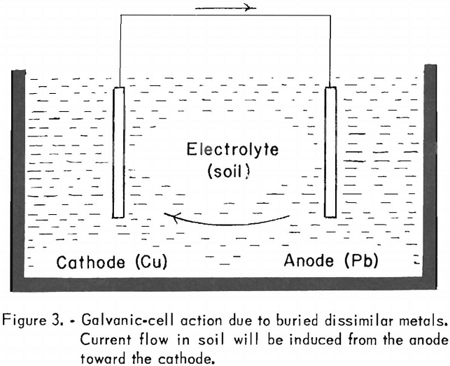
Since lead is above copper on the electromotive series, it is anodic with respect to copper, which is more noble, and a current flow will be set up from the lead to the copper. Thus, the copper will corrode the lead by merely being in its proximity. By the same reasoning, if magnesium and iron are buried in the ground and electrically connected, the magnesium will be corroded by the iron, or, stated differently, the magnesium will provide protection for the iron by setting up a potential difference that will tend to induce a current flow toward the iron mass.
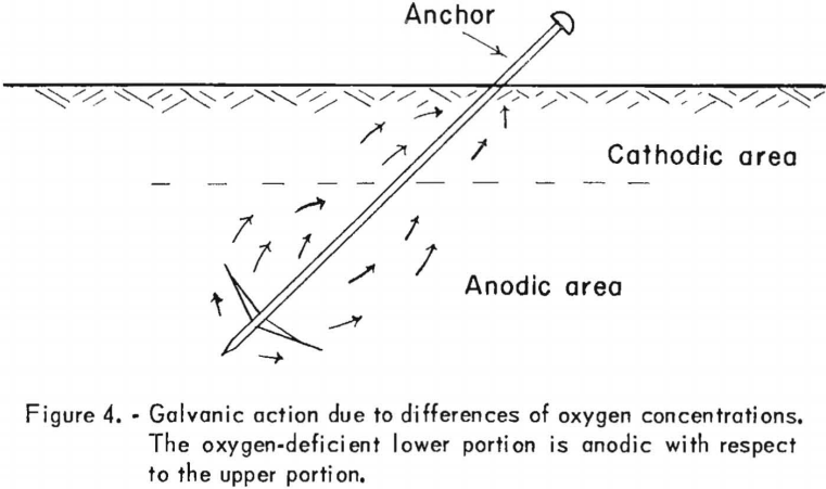
Dissimilar metals are not essential, however, for a galvanic-cell type of corrosive action. A galvanic-cell effect involving only one type of metal, may also result from a variation of the soil resistivity or merely from the difference in oxygen concentration. Differences in oxygen concentration will tend to set up galvanic action that is characterized by an anodic area in the oxygen-deficient portion. Figure 4 illustrates such a cell. Because the lower portion of the steel mass would be anodic with respect to the upper portion, which would be cathodic, current would flow as shown by the arrows, and the corrosive action effect would be confined to the lower portion. The discussion and illustrations of galvanic-cell effect show that, when two electrodes are involved the cathode is protected from deteriorating or corroding at the expense of the anode. Consequently, a metal structure that is made the cathode of a cell can be protected from corrosion, because damage results at the point or points where the electric current leaves and not at points where it is received. Twenty pounds of iron and 70 pounds of lead may be lost at such points by the action of 1 ampere of electric current over a 12-month period. The term “cathodic protection” is descriptive of the protective method, since it implies that the protection is accomplished by making the structure to be protected the cathode of a cell, thus receiving the current. Even though such protection was suggested as early as 1823 in conjunction with ship-hull protection, its extensive use has been developed only recently. Cathodic protection is usually accomplished by using two types of anodes, the galvanic anode or an electrolytic anode.
Galvanic Anodes
The galvanic anode, when used, is of a metal less noble or higher on the electromotive series. Thus, when connected to the metal structure that it is to protect, it becomes the anode of the cell, providing protection to the structure at its expense (deterioration). These anodes are commonly referred to as “sacrificial” anodes. When they are used, they operate automatically without the need of external power. For this reason, use is made of them in isolated places or to protect individual structures for which it is not desirable to provide electric power. Galvanic anodes are most commonly used to protect tower footings, brine-storage tanks, and water tanks. To protect industrial black-iron hot-water tanks, brine tanks, and home heaters, magnesium anodes are commonly installed in the tanks. For external protection of tanks in contact with the earth, the anodes are buried near by. It is interesting to note that the electrical energy potential of 1 pound of magnesium is approximately 1,000 ampere-hours, about one-half of which may be considered as useful energy in actual practice. This amount of energy can provide considerable protection, since the current values per square foot of surface to be protected are 0.01 to 5.0 milliamperes. The current density is governed by the type of surface of the structure protected; that is, whether it is bare or insulated. Factors that govern cathodic protection installations and energy required are: The area of surface exposed to corrosion, the soil resistivity involved, the type of surface, and the current density.
Electrolytic Anodes
In cathodic protection, when electrolytic anodes are used, electrical energy must be provided in the form of direct current from an external source. Rectifiers of various sizes and motor-generator equipment are used as sources of energy. This type of protection is generally used where considerable surface is to be protected and is extensively employed to protect pipelines. The authors believe that better understanding of the principles involved can be obtained if an existing system is used as an example; consequently, reference will be made in this section to the cathodic protection practices of the El Paso Natural Gas Co. All references will be limited to practice and experience of that company’s San Juan Division, with headquarters at Farmington, N. Mex. This system was chosen because it is a typical cross-country pipeline protective system and also because, due to its location, problems from interference, such as would be found in congested industrial areas, are not present.
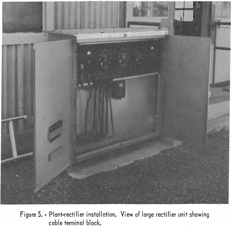
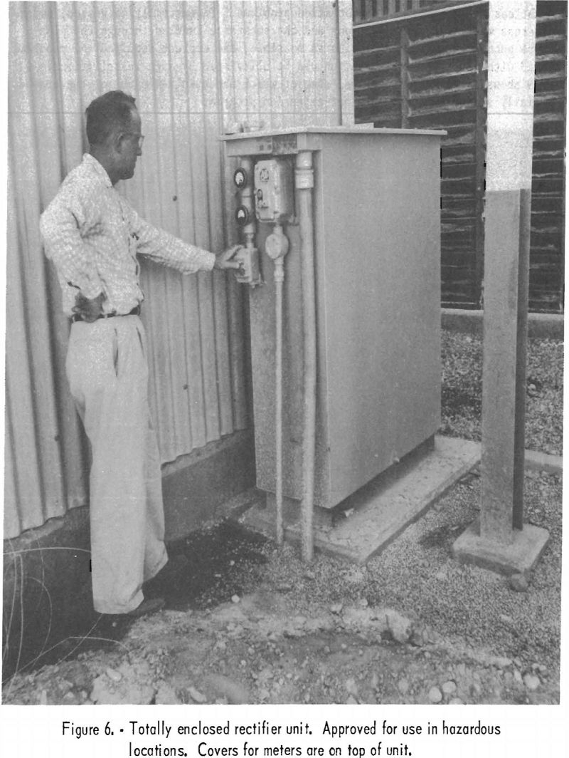
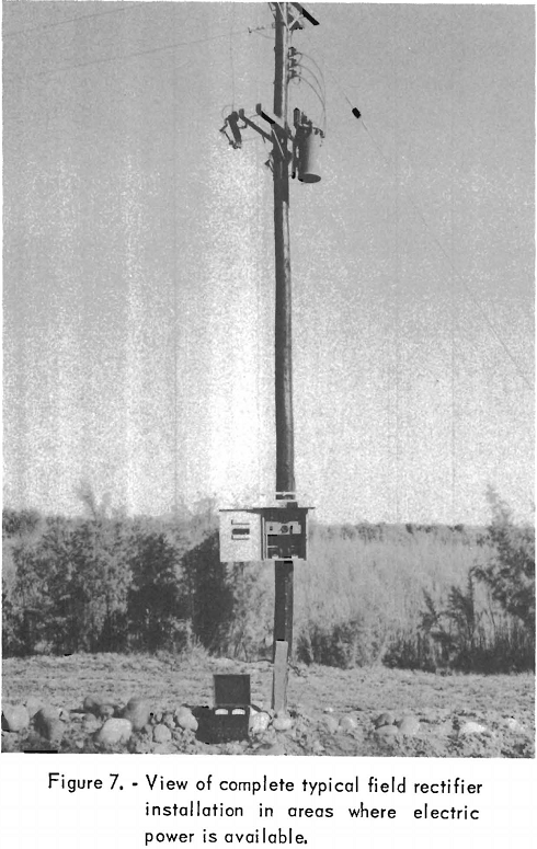
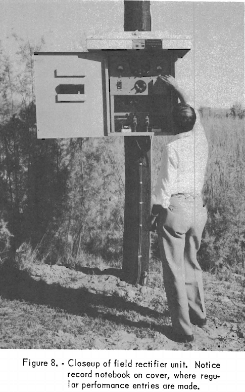
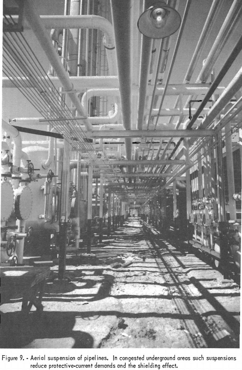
The main lines of the San Juan Division, consisting of 1,800 miles of 24- and 30-inch pipe in New Mexico and Arizona, distribute natural gas in these 2 States and deliver it to the California State line. By September 1956 cathodic protection had been provided for 75 percent of these main-line installations, and full coverage was anticipated. Secondary and gathering pipelines were protected only at trouble spots, except for on unusually corrosive field, which had full protection. Direct-current power was provided by 55 rectifier units of various sizes. Figures 5, 6, 7, and 8 show typical rectifier installations. Figure 5 is a view of a large rectifier unit used at a plant installation; figure 6 shows a totally enclosed unit designed for use in hazardous locations. Figure 7 pictures a complete field installation. The meter on the ground next to the short, square post in front of the power pole is not part of the permanent installation. The short post supports the terminals of the direct-current feeder cable and makes measurements more convenient. Figure 8 is a closeup view of the rectifier proper. Where cathodic protection is provided for pipelines on the field, 100-percent corrosion protection is expected; however, at plant locations only about 80-percent corrosion protection is considered within the practical scope. The numerous pipes and metal structures in the ground, because of their position with respect to each other, tend to shield some sections and prevent proper distribution of current. In new installations where extensive networks of pipes are to be used, proper grouping and bonding of pipelines can doubtless minimize cathodic-protection problems. In extremely congested, underground areas where weather conditions and the substance handled through the pipelines are such that aerial suspension is possible, the current required and problems connected with its proper distribution can be alleviated by such installations. Figure 9 shows network of pipelines, some of which had been taken out of the ground and aerially suspended during a plant-expansion program.
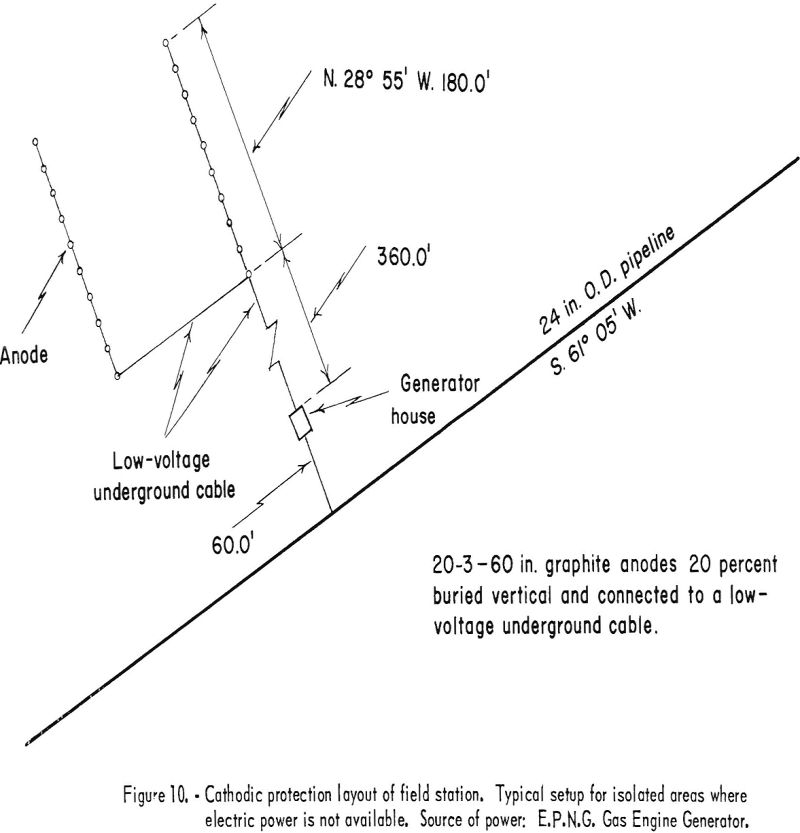
When external power in the form of direct current is used, it is supplied to the structure to be protected through anodes or “anode beds.” The negative conductor is welded to the structure, and the positive conductor is connected to the anode. The term “anode bed” refers to two or more anodes that are interconnected and operated as a unit. The number of anodes used is determined by the current required and its distribution. The El Paso Natural Gas Co. limits the current per anode to a 4-ampere maximum. In plants, anodes are distributed throughout the area according to anticipated current-density demand. A definite pattern is not followed, except that anodes are not installed closer than 10 feet to any pipelines or other buried structures that are to be protected. Anode beds used for pipeline protection are laid out in an “H” pattern. The anodes are installed along the two parallel lines and interconnected with low-voltage buried cable that is carried underground to the rectifier or generator. Figure 10 shows a typical cathodic-protection field station of the type used in areas where electric power is not available. The anode bed shown and its location with respect to the pipeline are essentially the same for either type of field-station installation.
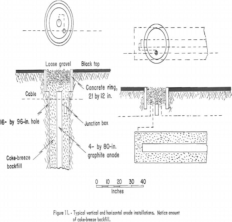
In order to obtain good distribution of current, the anode beds are placed not closer than 350 feet at a right angle to the pipeline. The average bed consists of 20 graphite anodes. The size of anode is not standardized, and both 3- by 60-inch and 4- by 80-inch graphite rods are used. Anodes are installed underground either horizontally or vertically. Figure 11 illustrates a method of anode installation for either position. The coke-breeze backfill is used to obtain more contact surface, which results in lower resistance. This method of installing the graphite essentially increases the anode life. A well-insulated positive conductor cable to the anodes is essential because slight damage to the cable will result in leakage of current.
Facets of a Cathodic Protective System
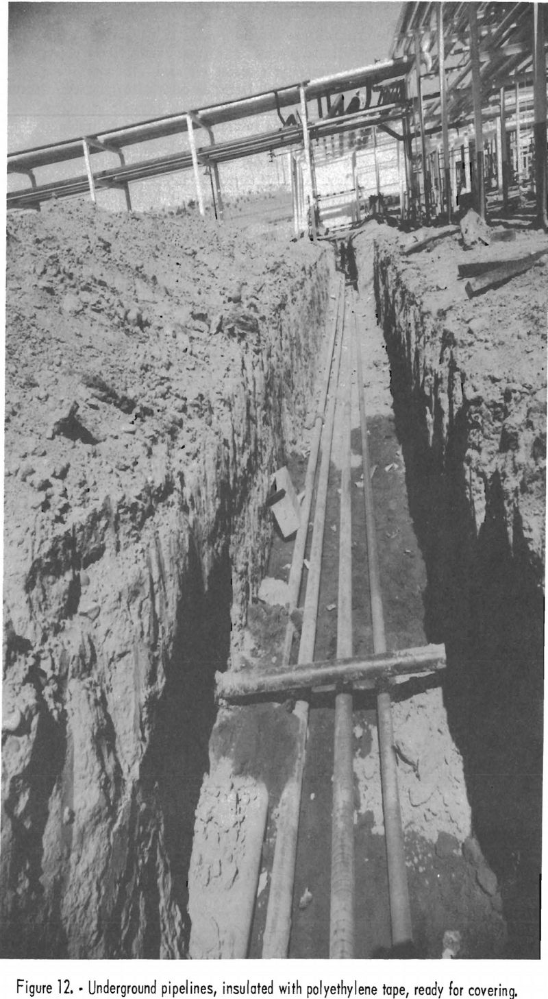
It is obvious from the discussion so far that, owing to the nature of this type of protection, the actual cost will be governed to a great extent by the electric-power demand whether galvanic or electrolytic anodes are used. The type of surface to be protected, therefore, will be a primary factor in determining protection costs. Bare metal surfaces can have current demands that will make cathodic protection uneconomical. In pipeline protection a good insulating coating is desirable. Figure 12 shows a new pipeline installation ready for covering. The crosspipe in the excavation is insulated with coal-tar enamel, while the newly installed lines have been wrapped with polyethylene tape. If corrosion is due mainly to the outward flow of stray or natural currents from a structure, it is logical that protective insulating coatings will reduce such current movements and the countercurrents necessary to nullify them. The question “Why cathodic protection if pipelines are thoroughly insulated?” may arise in the reader’s mind. El Paso Natural Gas Co. has found that coated pipes develop leaks even faster in spots than bare lines, because of concentrated local corrosive action. A 10-year record of one of the company’s protected lines, on the other hand, has shown no corrosion leaks while spot leaks developed on unprotected lines within a year.
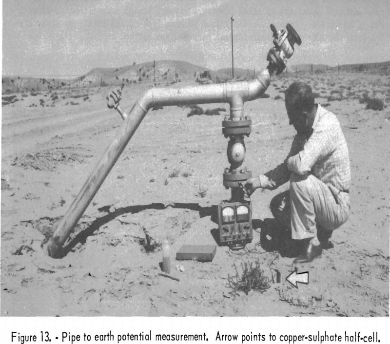
This publication does not discuss in detail the actual field methods and determinations necessary in designing a cathodic-protective system. Nevertheless, the commonly accepted criteria for an adequate protective system should be mentioned. Because of the virtual impossibility of measuring actual corrosive-current values at various points on a structure to be protected in order to determine the counter-current values required, corrosion engineers usually apply trial current values to the structure through temporary equipment. After the proper protection values needed have been established on this temporary basis, permanent installations are made. This is desirable also because the initial current requirements frequently are much larger than normal requirements for adequate subsequent protection. The accepted values for adequate protection, based on practical experiences, are determined on the basis of potential differences between the structure to be protected and earth. Such measurements usually are made with the aid of a half cell, which provides a good reference electrode; figure 13 shows a measurement being made with a copper sulfate half cell as the reference electrode to earth. The half cell is immediately at the right of the tumble weed in front of the meter on the photograph. The current values used by El Paso Natural Gas Co. for pipeline protection are such that pipeline potential will be limited to a maximum of -2.5 volts and a -0.85-volt minimum with respect to earth as measured to a copper sulfate half cell. This is a commonly accepted minimum value employed for steel structures by corrosion engineers. Potential differences higher than that (-1.10) are used for galvanized materials and values of -0.05 volts are generally used for lead cable-sheaths.
Stray Currents, Bonding, and Protective Grounding
The corrosion picture, as presented so far, has been viewed only from the natural-corrosion side. Stray electric currents, though not present in many industries, do real damage in mines and should be given due consideration. Because of the extensive use of direct-current electrical equipment in and about mines, corrosive damage from stray electric current is always present. Such damage can become serious in a relatively short time. In one instance of stray-current damage cited
by a mining company, mine-pump maintenance costs increased more than 120 percent of normal within 1 year, and at times pumping equipment needed reconditioning after 2 weeks of operation. Damage was determined to have been caused mainly by stray currents from the 250-volt, direct-current mine-haulage system.
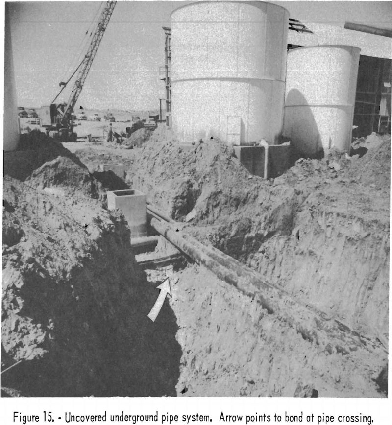
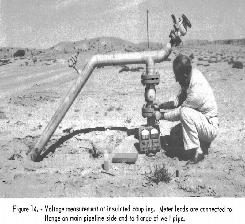
Often the power return of trolley-locomotive haulage systems is not adequately considered. Many systems use the track as a power-return conductor without additional copper or aluminum. In such instances, lack of an effective track bonding and maintenance program will obviously intensify circulation of stray currents. Such a condition is not only undesirable from the power-distribution point of view but also because of corrosion damage due to stray currents. In mines where considerable electric power is used, integration of all metal – water lines, air lines, metal cable sheaths, and cable armor – is considered good practice. Thus, the metal can be kept at earth potential by connecting it at regular intervals to the grounding medium. (Airdox lines are an exception.) This practice tends to minimize the establishment of potential differences, will minimize the possibility of arcing, and will provide shock protection for persons. However, it does not eliminate circulating currents. In Airdox systems, for instance, where circulating currents are undesirable, it is common practice to use insulating couplings at regular intervals. These couplings can also be used to advantage to insure isolation of a piece of equipment (a pump, for instance) where corrosive damage can result owing to electric current. Figure 14 shows a voltage measurement being made at such a coupling. Here the coupling is being employed to isolate a well casing from the main line to prevent it from “hogging” the protective current. Proper integration of metal structures that are being cathodically protected will also prevent shielding. Figure 15 shows a point at which pipelines cross. At such points and places where one set of lines tends to shield another set of lines or a structure, it is a common practice to bond the lines and structures.
Because both cathodic-protective systems and shock-protective grounding are based on establishing a low-resistance contact with the earth at the point of earth contact they can be combined. In many surface installations where cathodic protection is used, the anode beds or individual anodes are used as grounding mediums for the protective grounding system. When copper rods or cables are employed as grounding mediums owing to the position of copper with respect to iron in the electromotive series, the copper will receive cathodic protection at the expense of any iron or lead grounded to it. A system where considerable copper is used as a grounding medium is also difficult to bring under cathodic protection because copper tends to collect the current. In such instances, grounding rods of a different metal, such as iron or zinc, for which cathodic protection is provided, would be advisable.
