Table of Contents
The mold used in producing the raw briquet is shown in Fig. 15. This consists of two halves of hardened tool steel, held together by strong bolts. Into each half is milled a polished V-shaped groove, so that when the two parts are bolted together a square chamber is produced. Into one end of this chamber the plug D is inserted, and after filling the chamber with the material to be compressed, the plunger C, is forced into place. This plunger is steel containing tungsten, 16.5; chromium, 2; and carbon, 0.6 per cent., which, after heat treatment, has been tested under pressures exceeding 300,000 lb. per square inch. The face of the plunger was highly polished so that one surface of the raw briquet was available for micro-examination.
The design shown in Fig. 16 was a failure, since the adhesion between the briquet and the semi-cylindrical surface of the mold was greater than the cohesion across the section within the briquet itself, causing it to split while being removed.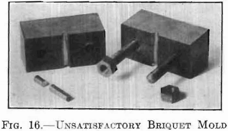
Compression was obtained in a Brinell hardness-testing machine, the ball, with its socket, being replaced by a special head. The press A was placed upon the adjustable table as shown in Fig. 17, so that the plunger came axially under the piston of the machine. This machine gave very
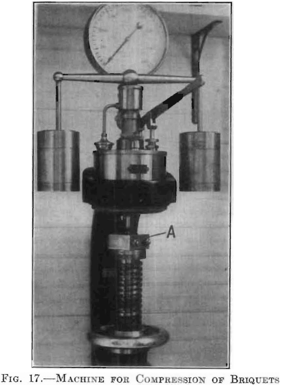
sensitive and accurate control up to a total load of 4,000 kg. Various total loads, when exerted upon the piston of 0.207024 sq. cm. in cross-section, are given in comparative values as follows:

Heat Treatment of the Compressed Material
Quartz-Tube Furnace
—Fig. 18 shows a quartz-tube furnace which used for the reduction of tungsten and molybdenum, and other oxides
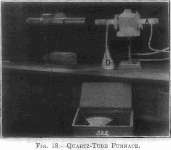
and salts; also for various purposes where heating in controlled atmosphere was desired but where very high temperatures were not necessary. In this, temperatures up to 1,225 °C. are easily and quickly reached. The fused quartz tube, A, has a glass window at one end, and at the feed end the plug, B, which can be removed for the insertion of the boot containing the material to be treated. Hydrogen, or other gas, enters through tube C and escapes through the bubbler D. A Meker blast lamp, E, was used for hearing. The method of sighting with optical pyrometer F is also shown.
Gran-Annular Electric Furnace
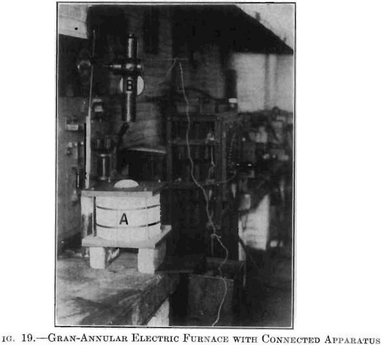
For temperatures up to 1,800°C. this furnace far surpasses any other type which the writer has used in experimental work of this kind.
Figs, 1 and 2 showed this furnace in detail. Fig. 19 shows a setup of the furnace, A, in series with cast-grid rheostat, ammeter, and switchboard. An optical pyrometer, B, points directly into the heating chamber of the furnace.
Electrical Resistance Furnace (Resistance of Charge)
The above furnace equipment, however, did not provide for the treatment of tungsten and molybdenum briquets, or those containing high percentages of these metals. Moreover, it provided no means for forging these ingots. This operation had to be carried out at high temperatures and in an inert atmosphere. Fig. 20 gives a vertical section of a furnace so designed as to
furnish temperatures ranging from that of the furnace room up to, and above 3,000°C., depending upon the material of the briquet, and also to serve as a forge for working the material into a solid mass while at a high temperature. This consists essentially of two adjustable electrode bars, A and B, fitted with fused tungsten contact surfaces, C, between which the briquet, D, is placed. Current is passed through the briquet which, by its own resistance and that between the contact surfaces, may be heated to any temperature up to its melting-point. An inclosed heating chamber, E, is formed by dropping the sliding cup, F, into a close-fitting recess made for it at the base. Gas is passed through the tube, G, into this chamber, from which it escapes through the outlet shown. This opening serves also as a peep hole for the optical pyrometer.
In operating, the bar, A, with its electrode and housing, F, is raised through its guides, H and I. The briquet, D, is then placed in position on the lower electrode, C, after which the upper electrode is lowered to contact. The inverted cup, F, is then lowered into place, forming the chamber E, through which is passed an inert gas, swiftly at first, to expel the air, and
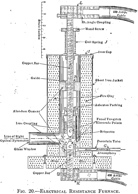
then slowly, as indicated by a bubbler in the purification train. To avoid the fracturing of very fragile briquets, and to prevent a resulting short circuit, the coil spring, J, with adjustable collar, is placed so as to support the excess weight of bar and cable.
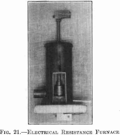
Fig. 21 is a photograph of this furnace with its door removed so as to show the different parts in place for heating. Fig. 22 shows the complete setup: A, being the furnace; B, a hydrogen generator; and C, an
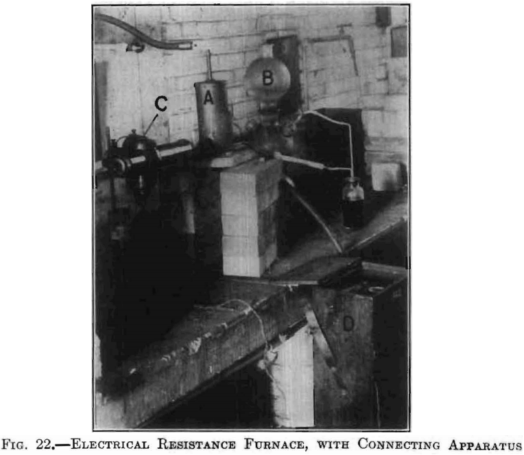
optical pyrometer in position for reading the briquet temperature, which is indicated on the scale contained in the case D.
Forging
This furnace was designed to be used as a forge, and at the same time to maintain the temperature at which the material of the briquets could be shaped. During this operation the lower bar was firmly supported, while blows were struck with a hammer upon the upper electrode. The increasing of the cross-section and the welding of the material would reduce the resistance considerably, resulting in a lowering of the temperature, unless an increased current were used; but, by pyrometric observation and current regulation during the forging operation, the temperature could be kept fairly constant. The peep hole permitted direct observation, of the briquet at all times.
Temperature Measurement
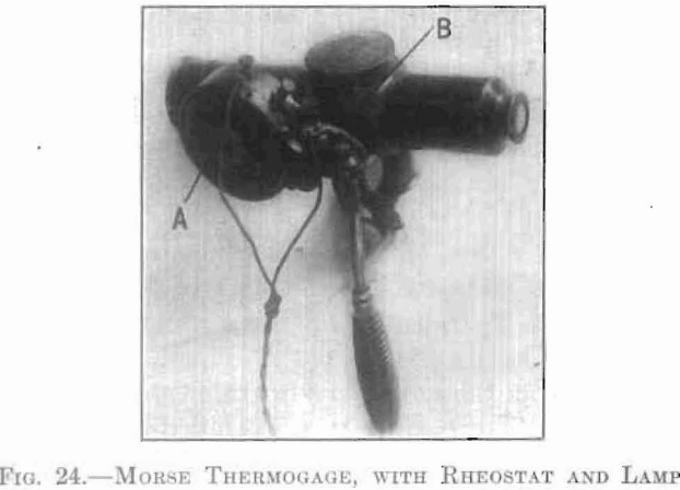
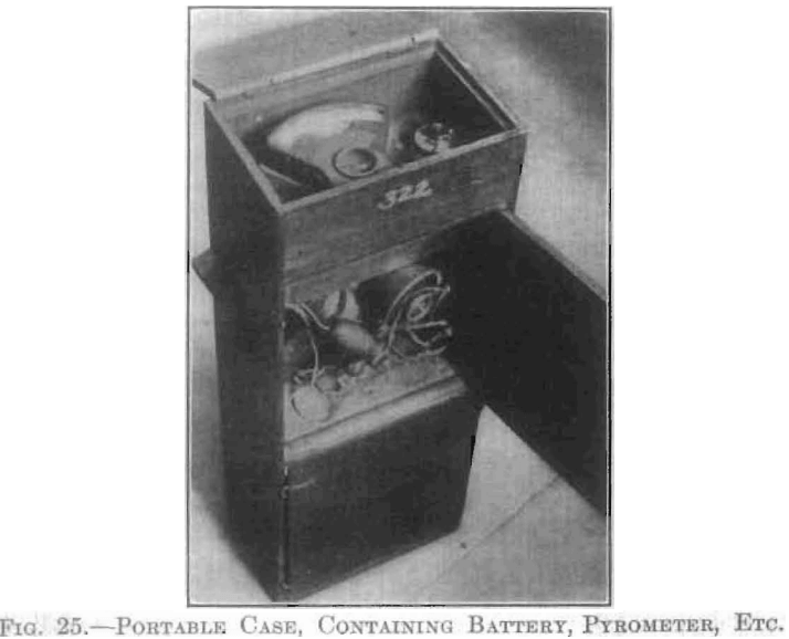
The conditions under which high temperatures were to be maintained did not permit the consideration of any thermometer or thermocouple method of pyrometry. The practical methods available were those based on the various radiation formulae, or upon optical observation. A review of this branch of pyrometry revealed an abundance of literature, upon the governing principles of these methods, and their practical application. Of the various types of instrument of this class available, that one was chosen as most practical under the prescribed conditions which involves a, direct telescopic comparison of the luminous radiation of the hot body with that of a standard source. There are two makes of this type; one, the Holborn-Kurlbaum, and another, of almost identical construction, the newer type of Morse Thermogage. The working principle is the same in both. A current is passed through the filament of a lamp, which.first becomes red and then, with increasing current, successively orange yellow and white. By interposing this filament between the eye and the hot body to be measured, the current through the lamp may be adjusted until the middle of the filament is of the same color and brightness as the object. At this point the part of the filament used for comparison will disappear against the bright background. The current, through the lamp, interpreted in terms of temperature, gives the temperature of the hot body. An absolute match of both color and brightness cannot be made, unless monochromatic light is used, because of the fact that the lamp filament and the viewed body do not radiate similarly. This comparison is facilitated by a suitable arrangement of lenses and lamp, as in the instrument of Morse, which was the one used in this work. This is shown diagrammatically in Fig. 23. A low-voltage incandescent lamp, L, with M-shaped filament is mounted in the focal plane of the objective, O, and the eyepiece, E, of a telescope is provided with means of focusing. The lamp circuit is shown connected through a battery, a rheostat, and a milliammeter. Fig. 24 shows this instrument with positions of the rheostat, A, and lamp, B. Fig. 25 shows a portable case containing battery, milliammeter, and pyrometer.
Temperatures were determined by focusing the instrument upon the briquet so as to bring its image into the plane of the lamp filament, then adjusting the current, by means of the rheostat, until the tip of the filament disappeared against the image of the briquet, when the temperature was read directly from the milliammeter scale (previously calibrated by checking current readings against known temperatures).
Below 1,200°C. readings were made directly, while above this tem-
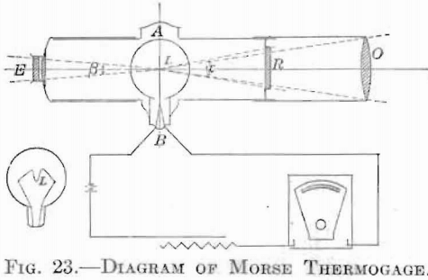
perature a neutral-colored absorbing “Rauch” glass (R, Fig. 23) was interposed between the lamp and the objective, in order to prevent the blinding effect of too great brightness, and also, to avoid overheating the standard filament. A new calibration was necessary when this absorbing screen was used. For temperatures above 1,900°C. it was found necessary to cut down the amount of light entering the pyrometer by means of a diaphragm, with the use of which temperatures up to that of the arc could be read.
The instrument was carefully standardized in all three ranges. The first, in which no absorbing glass was used, was carefully checked against an accurate thermocouple. The second range, using an absorbing light screen, was checked up to 1,375°C. against a thermocouple, and at higher temperatures by the freezing points of palladium and platinum. The Gran-annular electric furnace was used in this standardizing work up to, and including, the melting temperature of platinum, and for this purpose approximated very closely the desired black-body conditions. These standardizations gave current-temperature curves up to nearly 1,800°C., which could be continued by interpolation with a fair degree of accuracy, up to 2,000°C.
A third curve was formed by the melting points of platinum, iridium (2,200°C.) molybdenum (2,500°C.) and tungsten (3,000°C.). These latter points were obtained by sighting on electrically heated strips of the
metals formed into narrow wedges, as recommended by Mendenhall, which produces a deep cavity giving very near block-body conditions.
The tests on tungsten and molybdenum were made by grinding very thin a portion of a piece of wire, which, on account of the resulting small cross-section, heated very readily. These tungsten and molybdenum strips were arranged as lamp filaments in a glass tube, in vacuo. Readings were also made on fusing briquets of these metals, when heated, under operating conditions in the above described resistance furnace.
A final reading was made on the positive crater of the arc, accepting for this a temperature of 3,600°C. It has been shown that an absolute match of both color and brightness cannot be made, unless monochromatic light is used, or unless the lamp filament and object radiate similarly, which is seldom the case. All observations were, therefore, taken through red screens, which, with a radiation characteristic of about 2,000°C., gave a very narrow band with maximum of transmission at λ = 0.659µ.
In all readings care was taken to maintain axial symmetry and constant distance from the hot body to the objective, thus insuring a sufficiently large background, and also constant angles at ∝ and ξ.
The accuracy of this method of pyrometry has been fully proved and is such that between 1,000°C. and 2,000°C. the error of reading should not exceed 10°C. Above this range the error was found to be somewhat greater, but not so great as to interfere in any way with a duplication of desired conditions.
