Table of Contents
For many years, the Machinery Division of Dravo Corporation has been designing and constructing bins and bunkers as part of overall plant facilities. We have designed bins to handle a variety of materials including coal, coke, iron ores and concentrates, sintered and pelletized ores, calcined and raw limestone, bentonite, alloys for BOF shops, and even cast iron chips from machining operations.
In past years, rule-of-thumb design criteria had been to keep the sides of the bins as steep as possible and the outlets of the bin as large as possible. This criteria led to the design of bins with 60° to 70° side slopes and table feeders which were very large. Unfortunately, this meant trying to fit tall, skinny bins into a layout where minimum building height was required for obvious economic reasons. Like everyone else in the industry, we found that this design procedure was expensive and ineffective.
One of the first applications of the new principles of bin design was on a small bin which handled the discharge from disc filters. This bin was designed during the transition period between the old rule-of-thumb design and the newer Jenike approach. It was based on the steep sides, big opening concept, and it didn’t work. It was a classic example of a non-flowing, permanent storage bunker.
When the bin was filled, the head pulley slipped because the bin discharge was imposing excessive loads on the belt. Field personnel added a snub pulley to prevent the head pulley from slipping; and then the drive motor stalled.
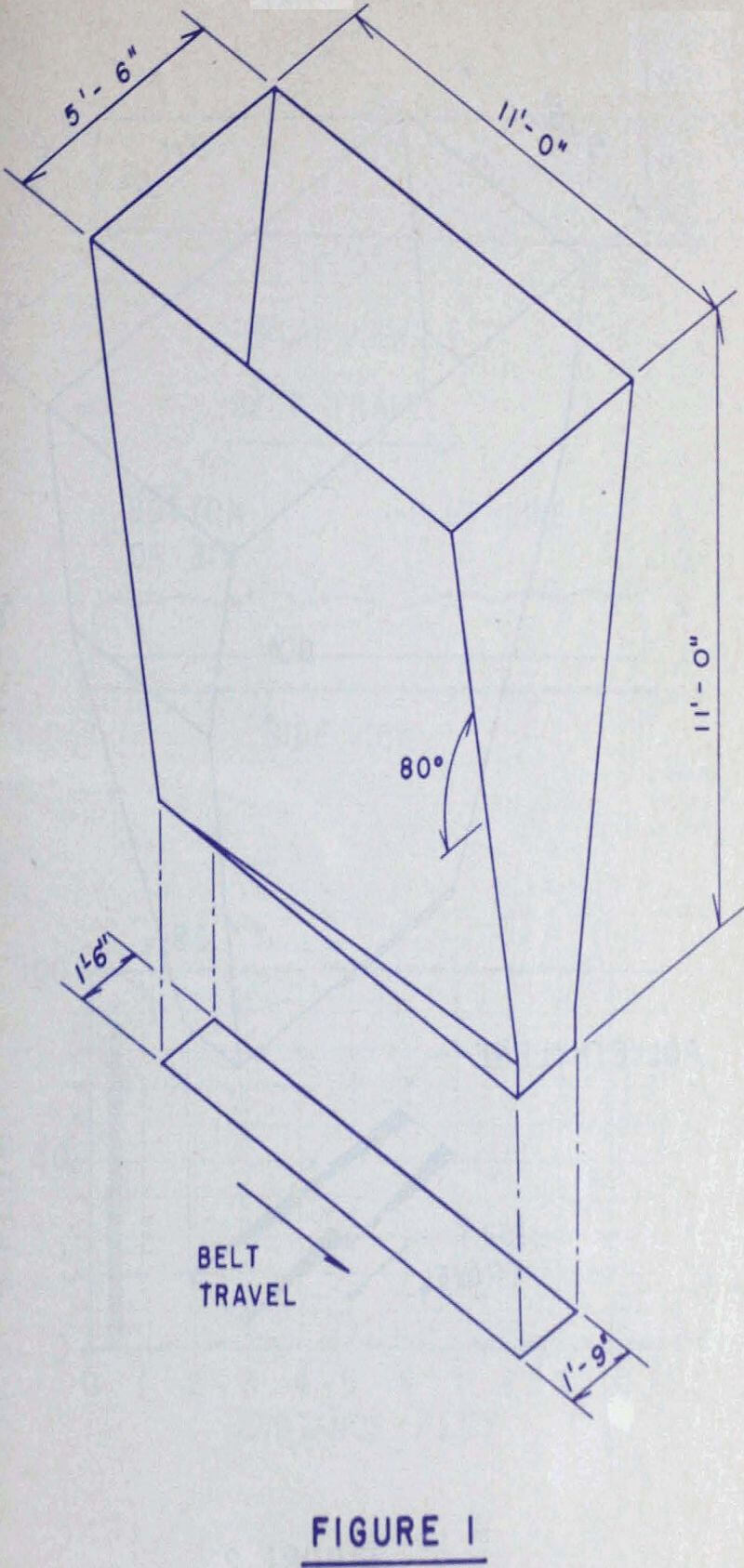
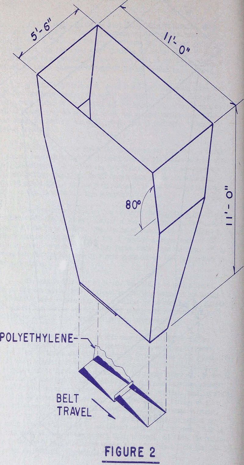
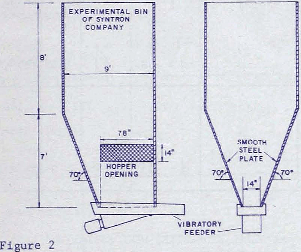
At this point, one of the men in our bin design program was sent to the jobsite. He tapered the two straight ends of the bin at a 70° angle, reducing the slot length by four feet. Of course, this modification was made by welding steel plate to the inside of the existing bin. This modification in itself did not solve the problem. It was necessary to place two tapered slots in the bottom of the bin and to drop the elevation of the first tapered slot so that it was two inches lower than the second tapered slot.
Design Criteria for Bin Feeders
Feeders are used to provide a means of control for the withdrawal of bulk materials from storage units, such as bins, bunkers, silos and hoppers. This control function can only be performed properly as long as the bulk materials flow by gravity to the feeder in a uniform and uninterrupted fashion. A feeder can do many things, but it should never be considered a suction pump.
Hopper and Bin Design
Feeders must be considered an integral part of the overall bin and feeder system. Improper design of either one of these parts will affect the performance of the whole system. Much effort has been devoted in the past decade on the development of functional design criteria for hopper and bins and this subject is far too extensive than we could hope to cover in this paper. Suffice to say, that the integrated concept of bin and feeder design requires quantitative analysis of the bulk material characteristics before attempting the design and selection of the components.
The design of a feeder system must start first with the proper dimensioning of the hopper outlet to prevent arching, doming or ratholing. The hopper opening size should be large enough to allow passage of the bulk solid at the required maximum discharge rate. A feeder can only throttle the flow.
Confronted with the higher experimental values of feeder loads, we consider strongly the possibility that the stress field shifts and rotates above the feeder, causing a different vertical stress condition. The highest value would occur when the major consolidation pressure would act downwards. This major consolidation pressure ( ∇ ) can be expressed by
∇’ = rBff/1 + m
where, r = bulk density
B = width of hopper opening
ff = flow factor
m = shape factor (m = 1 for circular opening and
m = 0 for slot opening)
The bin wall pressure (∇’) at the opening is expressed by ∇’ = (C)rB where ( C ) is a factor dependent on hopper geometry and material properties, also available in graph form in Jenike’s Bulletin 123.
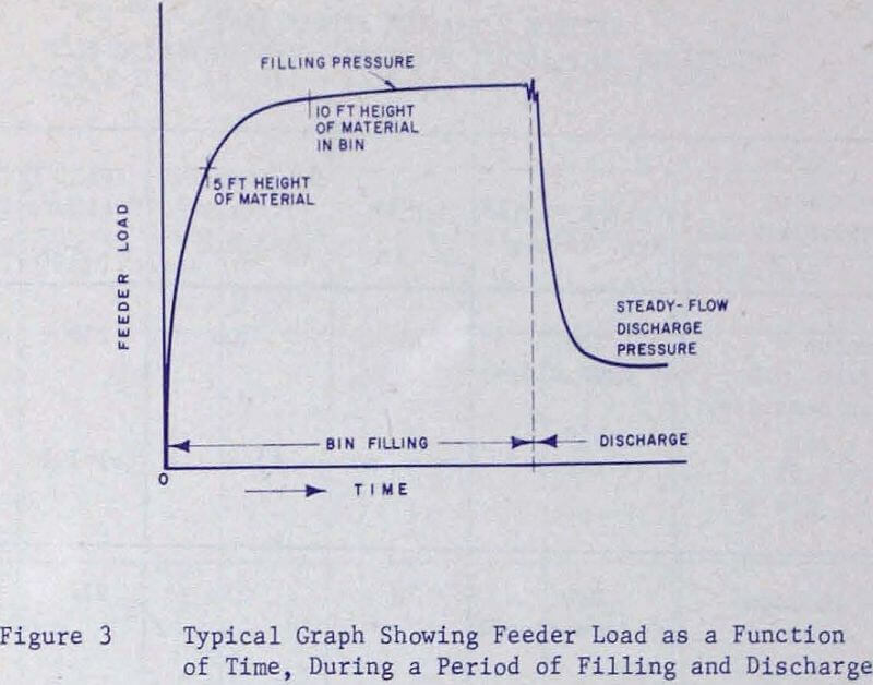
The filling pressures on the feeder are usually 2 to 4 times as large as the steady-state-flow discharge pressures of the feeder depending on point of impact and filling rate. If 8 to 10 ft. of height of material is left in the bin when the feeder stops and the bin refilled, then the filling pressure rises only 10 to 20% above the discharge pressure. It is therefore recommended to avoid impact of material directly over the bin-opening during filling and to leave some material in the bin over the opening when refilling.
Belt Feeders
The slot-type belt feeder is one of the most economical feeders for bulk solids. Although this type of feeder has been in use for about 50 years, it only has recently found industrial acceptance. Properly applied, the belt feeder lends itself nicely to low first cost, dependable operation and automatic control.
Belt speeds vary from 1 fpm up to 50 fpm for ore and stone, and up to 100 fpm for softer and lighter materials such as coal. Either a slider plate or idlers may be used to support the belt. The belt is usually kept flat with side skirting to retain the material. The belt pull is made up of different frictional and shear elements:
- Friction between belt and the slide plate or idlers.
- Friction between material and belt.
- Friction between material and hopper walls and skirting.
- Shear forces within the material at the gate regulating depth.
- Pulley and bearing friction of terminals.
Each of these elements should be calculated independently, but insufficient information exists today to evaluate them separately with good enough accuracy.
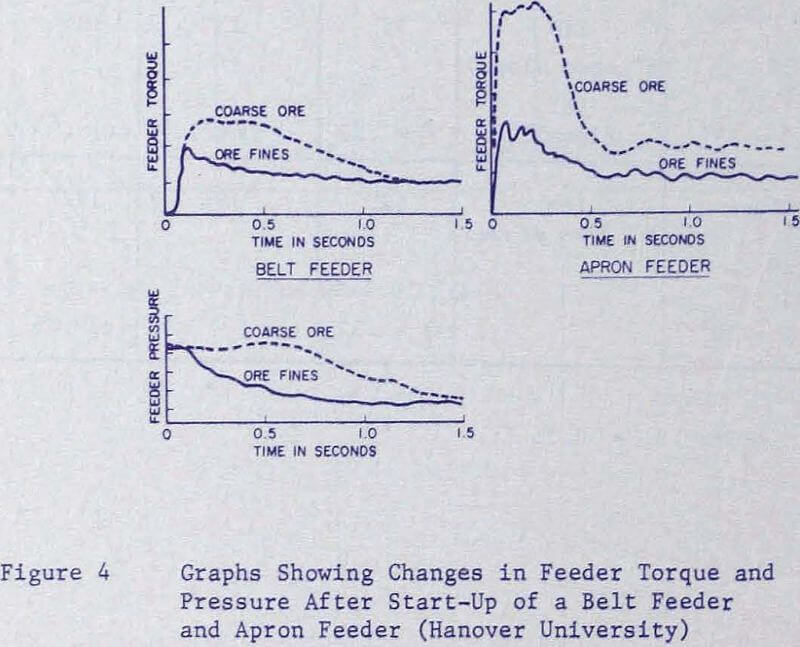
The starting torque of feeders usually show a peak at the very beginning, which lasts for less than 1 second. Note the higher torque requirements for coarse material. For comparison, the torque output of the same size apron feeder is shown. The belt feeder shows a delayed rise of its torque curve, which is caused by the stretch of the belt.
To avoid excessive starting torques, it is advisable to provide an elastic support of the feeder so that the feeder can deflect a little bit under load. Many times soft rubber impact idlers may do the job, or rubber pads underneath the idler stands.
The bed height under the gate has a definite influence on the shear force 12), Beyond the restriction of clearance underneath the strike-off point being at least 2 times the maximum lump size, there is a width, length and height interaction affecting the shear force. It appears that the bed height should be at least 1/3 of the hopper opening width for slot ratios of L/B = 3. The bed height should increase for larger slot ratios in order to minimize the shear force.
Apron Feeders
This type of feeder is recommended in those cases where impact conditions or size of lump prevent the application of belt feeders. Truck-dump hoppers and hoppers underneath primary crushers usually have apron feeders. The initial cost of these feeders is 2 or 3 times higher than of belt feeders, and the power requirements are nearly twice as much.
For increasing severity of service conditions and impact, apron feeders can be supported by either chain rollers, outboard rollers, frame rollers or solid steel idler rolls underneath the apron matte. Travel speeds are up to 50 fpm.
Vibratory Feeders
The process involved in determining the design parameters of a vibratory feeder is rather complex. Material on the trough is subjected to the forces of gravity, normal forces, friction forces, and impact forces. Basically the feeder trough or pan is driven by a nearly sinusoidal force at some angle to the trough. When the feeder is operating the trough is oscillating along a straight line the amplitude and direction determined by the driving force.
The resultant of the directed linear vibration is a repetitive series of throws and catches that moves the material on the trough. The particle is in contact with the trough for approximately one fourth of the drive cycle shown as point “A” to point “B”. When the particle leaves the trough it travels with a uniform horizontal velocity but the vertical velocity gradually decreases due to gravity. At some later point the trough again contacts the particle and the process is repeated. This process then conveys material along the trough from 0 to 80 feet per minute depending upon the combination of drive frequency, amplitude, drive angle B and feeder inclination. These parameters as well as material flow depths and feeder trough widths allow material to be delivered at rates of several pounds to more than 3000 tons per hour.
Various manufacturers of vibratory feeders have selected different operating parameters for the trough movement. Operating frequencies generally vary from 600 to 7200 vibrations per minute, amplitudes range from a few thousandths of an inch up to one inch or more, and selection of drive angle B, goes from 20° to 45°. Certainly for any given material there will be an optimum operating condition combining frequency, stroke and drive angle; it would seem reasonable for example that for particles such as fine limestone, flour and cement that tend to cling to the trough, more of a vertical component of stroke should give higher delivery rates. At the same time, abrasive material such as scrap steel or coke which flow easily would do less damage to the conveying surface of a short stroke, high frequency machine.
For a given drive angle the delivery rate depends approximately on the product of frequency and stroke, so that in lowering one the other must adjust for this. For short stroke, high frequency (3600 CPM) operation electromagnetic units are chosen, conversely for long stroke, low frequency operation various choices of motors with eccentric weights are being used.
Tuned feeders that use rotating eccentric weights are referred to as electromechanical feeders. In these feeders the operating frequencies are comparatively low, using 900 to 1800 RPM motors mounted on the reaction mass. Spring systems may consist of rubber in shear, steel coil springs or pneumatic springs, or any combination of these. Dual counterrotating motors may be used without mechanically connecting their shafts provided they are on a common rigid frame in which case they will sychronize. The same effect may be obtained by using a single motor driving two sets of gear connected shafts by means of a V-belt. Each of the shafts have equal eccentric weight. Control of flow rate for the electromechanical feeder may be accomplished in one of three ways 1) varying the speed of the drive, 2) varying the tuning by changing the spring stiffness and 3) varying the value of the thrust by changing the amount of eccentric mass. While in the past variable rate feeders have been almost entirely of the electromagnetic type, recent developments of control methods by manufacturers of electromechanical units have overcome some of the inherent flow regulation problems inherent with motor drives.
Feeder Loading
There is a natural tendency for vibratory feeders to withdraw from the front portion of a hopper opening. To help elevate this problem, proper hopper design will permit material to be placed on the feeder at the far end of the pan. The front wall of the feeder, on the contrary, should be more shallow than that required for flow along the walls, 50 – 60° is acceptable for most materials. This permits a large reservoir of slow moving material to be just above the gate – the portion of the hopper that will naturally withdraw the fastest. As a result of the steep rear wall and the shallow front wall the hopper will empty quite uniformly. It is best to have the side walls vertical or at least steep enough to allow flow along the walls.
Flow velocities vary from 20 to 60 feet/minute depending on the material properties, feeder amplitude and operating frequency. It is interesting to note that the flow rates in general will increase for a given feeder with proper hopper design, and the amount of neck down from the gate to the end of the feeder becomes less – both tend to increase delivery rates.
When high capacities are required of a feeder the pan is sloped down from 6° to 15°. Some installations have boosted delivery rates by more than 50% with a 10° downs lope. A rule of thumb value is a 2% delivery increase per degree of downslope. This is obviously the approach to get the most tonnage per dollar investment. By downsloping, the feeder is getting some “free” assistance from gravity. With increasing downslope, however, there is an inherent loss of control. The converse holds true, upsloping the feeder gives better control but lowers delivery rates considerably. In installations where the feeder is given some downslope, skirts are nearly always required. The same recommendations of tapering the skirts holds true as for the level feeders as discussed above.
Correlation of Solids Flow Theory with Actual Bin Operation
In recent years the procedures for functionally designing bulk storage bins and hoppers have evolved from qualitative guess and try methods to a quantative method based on theory and tests of the bulk solid to be stored. Before any meaningful correlation of solids flow theory with actual bin operation can be made we must understand something about the basis of the theory and what it is capable of predicting. The flow solids theory is based on principles of equilibrium of forces, neglecting dynamic effects, and continuity of the mass with an experimentally derived description of a continuously deforming bulk solid. The bulk solids are treated as a continuum, that is, as a homogeneous mass in which individual particles have no meaning. This suggests three limitations in using the theory.
The particle size distribution, moisture, content and chemical composition of the sample and the temperature and atmospheric conditions that the sample, will be subjected to must be faithfully reproduced. If this is not done, false results, may be predicted as in the case of the following sample of coal, that was supposed to be causing rat-holing problems. Flow property tests showed that the coal was very, free flowing, even at a 10% moisture content and that no hang-up problems of any kind should occur.
There, are essentially two predictions by the theory. One is the critical-dimensions to eliminate bin hang-ups, the other is the predicting of flow patterns in bins. When the theory has been used to design new facilities safety margins have been used to insure flow. In such cases the only conclusion is that the bin worked satisfactorily so the design was on the safe side. However, when working with the redesign of existing facilities with the maximum use of existing, equipment the design is often specified very close to theoretical as in the case of a foundary sand bin.
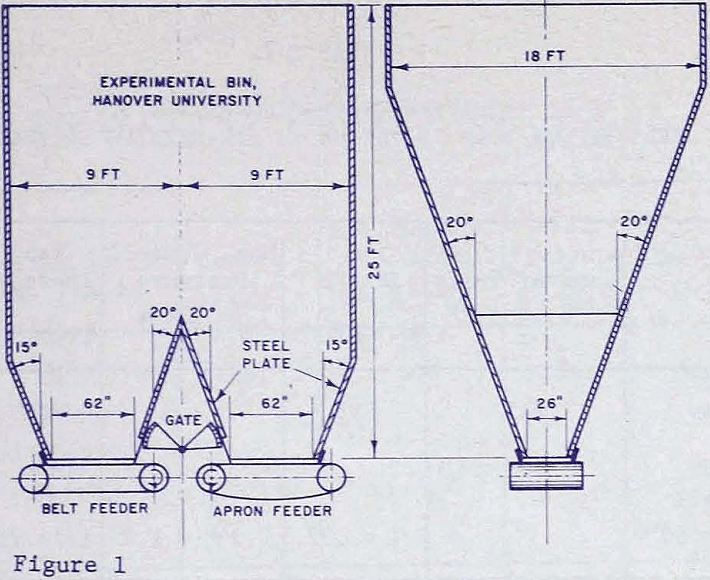
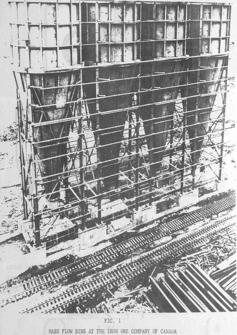
Very often the theory predicts that steep mass-flow hoppers are required to prevent bin flow problems. The question then arises, it is practical to design such steep hoppers? One of the earliest mass-flow bins was constructed by the Iron Ore Company of Canada at Carroll Lake. These huge mass-flow cones, shown in Figure 1, stand over 100 feet high and handle specular hematite concentrate. They were designed according to the theory to cause mass-flow and thereby eliminate much of the segregation problems anticipated. These cones showed that such hoppers can be built within the economic guidelines set for the project.
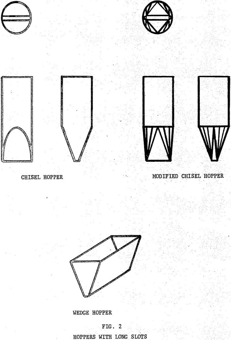
Another way of reducing the slope of a mass-flow hopper is by using a long slotted opening as illustrated by the chisel, a modified chisel, and wedge hoppers. The flat hopper sides parallel to the slot length can be made from five to ten degrees less steep than a conical hopper and still produce mass-flow. However, special care must be taken when using long slots to insure flow across the entire length of the slot.
Bin Operations use of Stainless Steel Conical Hoppers
Prior to April, 1961, the coal charge to Clairton’s coke oven batteries was 3″ x 0″ mine washed coal having approximately 6.0% to 7.0% moisture. Even at this size and moisture content, the arching, rat-holing and hang-up was excessive and the effective live storage of coal was only 60% to 70% of the rated capacity of the coal bunkers, depending upon the moisture of the coal. In addition, many production delays were encountered in the time and methods required to fill the larry cars.
The coal bunkers that serve Clairton’s coke oven battery operation were built in 1918 and 1924 to handle 5″ x 0″ run of mine coal at 3. 5% to 4. 5% moisture. The slope angles of the pyrimidal hopper section of the bottom of the bunkers range from 55° to 63°, which made possible a fairly large live storage at that size consist and moisture without the use of stainless steel slope sheets.
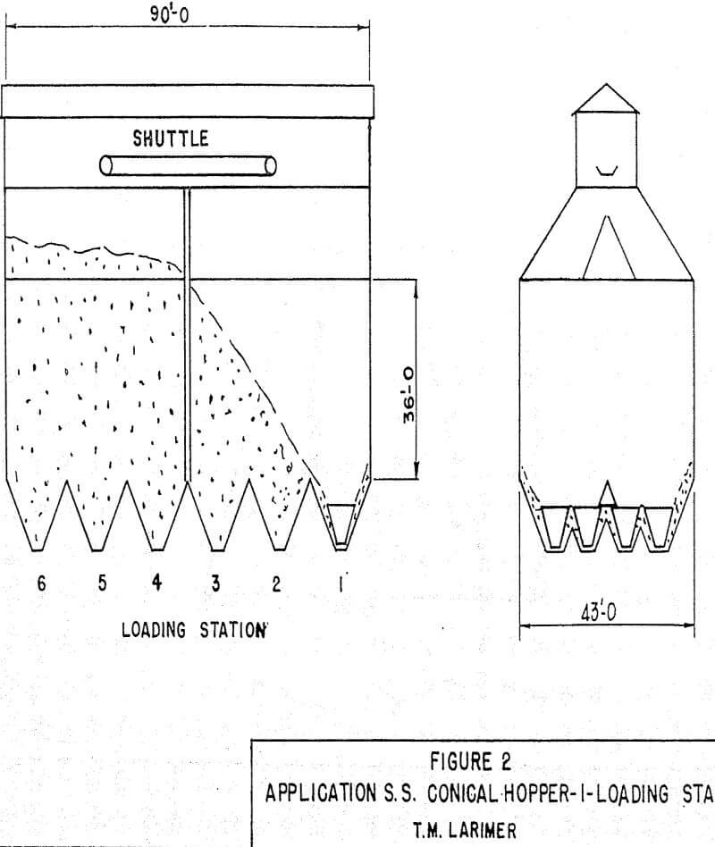
In 1965, just before the use of pulverized coal was extended to ten additional batteries, the U. S. Steel Applied Research Laboratory recommended the use of stainless steel conical hoppers, having slope angles of 67° from the horizontal. It was expected that these hoppers would promote mass flow of pulverized coal through the bunkers because of their design and greater slideability than carbon steel. Coal was drawn from the No. 1 station until empty, resulting in a withdrawl of approximately 45% of the coal, in one end of the divided bunker. Tests were then conducted with varying rates of oil and water additions to aggravate the “stickiness” of the coal and we found that the cones performed well under all circumstances.
In that none of the coal bunkers could be taken out of service completely for installation of the conical hoppers without interrupting battery operations, only one end of the divided coal blinkers was cleaned out at a time preparatory to installing the cones.

