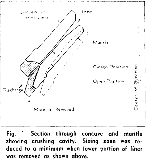
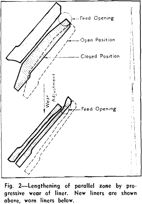
In these times of rising labor and material costs, it has become more and more necessary that attention be paid to some operating details which, in their obscurity, may be the key to major economies. Liner wear in crushing cavities of secondary and tertiary crushers can become an appreciable cost item when the material to be crushed is hard and abrasive. This item of cost not only includes the value of the crushing members, but also more intangible costs such as labor and lost production due to more frequent replacement.
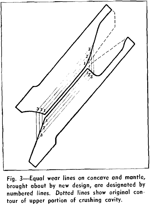
The material being crushed was a very hard graywacke and the crusher was closed-circuited with a screen having .232-in. slotted openings. Equal wear lines on both concave and mantle are designated 1, 2, 3, etc. The method of development of this contour is as follows: Since adjustment for wear is vertical, corresponding intersections of wear lines and vertical lines developed concave and mantle contours which maintained equal but lengthening wear surfaces in the parallel zone.


Solid lines show the worn sections of several contours superimposed upon the original. These contours were obtained by torching a section from the worn members and tracing the contour on a full size section of the original. It is to be noted that a surprising uniformity of wear was obtained. As nearly as can be ascertained, the average capacity increased from 90 to 104½ tons per hr, or 16 pct, and the total average tons crushed per set of liners increased from 71,000 to 84,000 tons, or 18 pct, in spite of the fact that the liners were 15.6 pct lighter. The rate of liner consumption was 0.062 lb per ton crushed as compared to 0.087 lb per ton crushed with the earlier design.
Because of the encouraging results obtained with the new type of cavity on tertiary crushers, the basic features were applied in a broader way in the secondary crushing stage. Apparent reduction ratios are generally greater here than in the third stage, although the actual difference is not great. A 12-in. nominal size feed from a primary will seldom have over 10 pct in the 10 to 12-in. size even when passed over a scalping device of reasonable openings.
Heretofore, it has frequently been necessary to recommend oversize crushing units to meet feed size limitations, particularly in the case of low-tonnage operations. The redesign of cavities, as outlined here, has permitted a better choice of crushing unit for the duty required, with lower first cost and more economical operation. The use of the so-called controlled feed cavity has enabled a large producer of limestone aggregate to standardize on two-stage crushing plants, producing all required sizes of aggregate except sand.

