Table of Contents
The minerals industry in the field of Underground Mine Design is presently faced with the problem of meeting a rapidly increasing domestic and foreign demand for its mineral resources. This increased demand has added to the problems already plaguing the industry increased land, labor, and material costs; increased foreign competition; more rigid Federal and State mining laws pertaining to health and safety; increased public awareness of air, stream, and land pollution; and increased public concern of mining practices and conditions within the mines. In addition, the industry must live with problems created by past generations such as abandoned strip mines, acid mine water drainage, and abandoned unmapped underground workings.
The “need” for a healthy, viable minerals industry within the United States has been stated many times over. In addition, it is desirable, if not a necessity, from the viewpoint of the consumer and the national economy that the cost of making available a mineral resource be minimal. The development and utilization of scientific mine planning will be an invaluable aid to the accomplishment of the design and operation of profitable, safe, healthy, and environmental-preserving underground mining operations.
Mine planning is usually divided into three areas: long range, short range, and production scheduling. A long-range plan defines the economic limit of mining at the termination of the deposit’s mining life and serves as a guide for short-range plans.
In the process of winning a mineral resource, short-sighted goals can lead to costly development and possible loss of some resource to future exploitation. It is for this reason that this report will be primarily concerned with long-range planning.
A trend within the mineral industry, not unusual in other industries, is toward the development of large, complex physical plants in an effort to reduce unit costs. The trend is toward fewer mines employing more men. For example, in Colorado in 1960, there were 607 noncoal operating mines with a yearly employment of 5,220 men, compared with only 353 mines employing 6,660 men in 1970 as given in Colorado’s yearly report by the Deputy Commissioner of Mines. This trend seems likely to continue.
Another factor that has had a profound effect in reducing the number of small operations has been stricter mining laws. For example, as a result of the Coal Mine Health and Safety Act of 1969, it is stated that “In any coal mine opened after March 30, 1970, the entries used as intake and return air courses shall be separated from belt haulage entries” This regulation has sharply increased mining costs for the small coal mine operator using belt haulage by forcing any egress into a coal property with a minimum of three interconnected parallel entries. In the past, the mine operator was able to operate with two entries, one for intake air and the other for exhaust air. The economic impact of this law has been significantly less for the large mine operator, who now usually operates with an excess of five parallel main entries.
With the trend towards larger, more complex mine plants comes the increased responsibility of the mining company to comply with the needs of society as a whole, thus increasing the needs for good scientific mine design.
Today, coal companies are looking at properties for exploitation that may contain multiple seams within a very complex geologic environment covering many square miles. Additional problems, such as land ownership, oil and/or gas wells intersecting the mining property, highways, surface buildings, power-lines, canals, water tables, and entrapped methane, present a mining company with many problems not encountered only a few years ago.
The need for sound mine planning within our complex sociological framework is well documented. The purpose of this report is to develop a tool for assisting the mine operator to efficiently evaluate alternative approaches to mine planning.
The mining engineer is faced with the need to respond quickly to modify a mine design to satisfy rapidly changing economical, ecological, and sociological constraints. Heretofore the mining engineer could be content with comparing only a few alternative mine designs. Today, he must explore many alternative plans constrained by factors unknown only a few years ago.
In terms of long-range planning, the design engineer must be alert to the changes in the overall mine plan resulting from changing land, material, and labor costs or the introduction of innovative mining concepts. Possibly the design engineer will be requested to make a quick evaluation as to whether or not a company should extend a lease on an unexploited piece of land. In terms of short-range planning, an overall mine plan is also extremely important to the engineer in charge of scheduling mine development and production to meet demand commitments. The end-of-life or ultimate mine layout is also of concern to the engineer in charge of designing efficient ventilation, haulage, drainage, and electrical networks.
The objective of this report will be to develop a method for defining- an ultimate underground mine layout consistent with economic, safety, and conservation constraints. Knowing the ultimate mining configuration is vital to the efficient layout of the mine development, mine development is here defined as a network of primary accesses through which the bulk of the material is moved to the surface mine facilities from the mineral producing areas.
To achieve this objective, the following four criteria were used as guidelines in developing an algorithm for delineating the economic limits of a mineralized property:
- Mine layout should be everywhere accessible to the surface.
- Algorithm should be applicable to the general mineral-type deposit.
- Algorithm should be capable of solving realistic size problems.
- Technique should be user oriented.
Criteria 1, 3, and 4 above should be self-explanatory. What is intended in criterion 2 by the term “general mineral-type deposit” is that the distribution of economic worth may be freely dispersed throughout some three-dimensional rock mass. In other words, the distribution of mineral context need not be rigorously prescribed by some simplistic mathematical function. The problem of forecasting the distribution of mineralization within the earth’s crust is recognized. The problems of delineating a mineral deposit are referred to in Becker and Hazen.
General Underground Mining Problem
In view of the increasing complexity of the general mining problem, mining companies are now beginning to rely upon mathematical techniques and tools to predesign the layout of a mining operation. The following sections contain a brief review of literature, detail a means for expressing the general ultimate underground mine layout as a network, and define a general formulation of the problem.
Literature Review
Perhaps one of the best single sources of operations research techniques applied to mining problems is a recent book published in Hungary. This book describes some techniques for such problems as the location of a shaft, determination of level spacing in a dipping deposit, and the “optimal” location of crosscuts. This book does give a wide variety of simple applications for a wide variety of facility location type problems. The term “optimal” used here and discussed later in this paper will be used in a strict mathematical sense.
In the area of ultimate underground mine layout there has been a notable lack of published papers. The problem of designing an ultimate open pit has generated much more interest in the past several years than has the subsurface problem. The ultimate open pit problem has been approached by Lerch and Grossmann using a dynamic programming technique, Johnson employing both a dynamic programming technique and a network-flow model, and Ganthier and Gray using a heuristic approach. An interesting and computationally practical approach, based upon the dynamic programming of Lerch and Grossmann, is given by Johnson and Sharp. All of these approaches use what is referred to as the “block concept,” which is simply a method for subdividing a mineral deposit into discrete minable units formed by set of more or less orthogonally intersecting planes. Discrete block units appear to be a reasonable basis for a subsurface excavation model for the following reasons:
- Block concept is accepted and used within the minerals industry for ore reserve and delineation studies.
- Blocks can be made to conform with most mining methods used within the industry today.
- Block inventory is easily stored in a digital computer.
With respect to the ultimate pit problem, the blocks themselves help to describe a pit wall. In comparison, the subsurface problem need only imply connectivity of blocks; that is, existence of a passage from any set of minable blocks to all others in the set to be mined together with a passage to the surface.
Definitions and Sample Problem
The ultimate underground problem becomes more amenable to analysis if a weight is assigned to an individual block equivalent to its worth without regard for its neighboring blocks. In terms of utility, the block worth might represent the least-cost or potential profit that a mining concern
would reap given the fact that any particular block is physically mined. Dependent upon the problem, all block weights might represent a true cost (negative weight), for example, a tunneling operation. In a tunneling problem the contractor or mining company is only concerned with finding a least-cost passage between two points. Therefore, in terms of the block model, it would be a connected sequence of blocks between two points in which the individual blocks would be equivalent to a small segment of the tunnel.
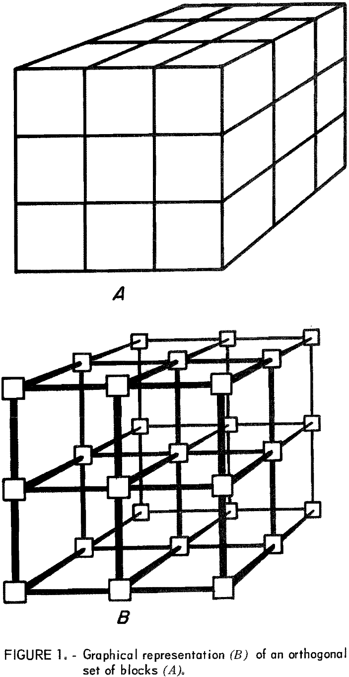
Figure 1-A gives a graphic illustration of how the block might be interpreted in three-dimensional space where the length, width, and height of each block would be determined by the user. Figure 1-B is a graphical illustration of the set of blocks in figure 1-A above. Each block has been pulled apart, figure 1-B, but remains connected to its adjacent neighbors by a line. For purposes of discussion, the lines will be referred to as arcs and the squares (dots or circles) as nodes. These terms are consistent with those used in network theory.
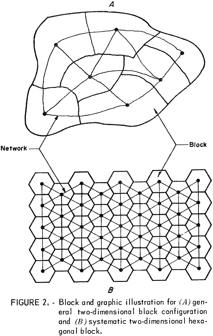
A block need not be defined as a cube. Figure 2 illustrates two different examples of a basic two-dimensional block configuration. Of interest is what may be represented by these block configurations again as a graph—similar to what was done in figure 1. The nodes represent the blocks and an arc indicates that two nodes are adjacent geometrically to one another.
Figure 3-A illustrates a two-dimensional graphic representation of a set of blocks. A value or weight which implies the worth or cost of mining that particular block has been assigned to each node (block). The path given in figure 3-A as a heavy line is the least-cost path connecting nodes A, B, and C. The problem of finding a connected subset of maximum total weight from a
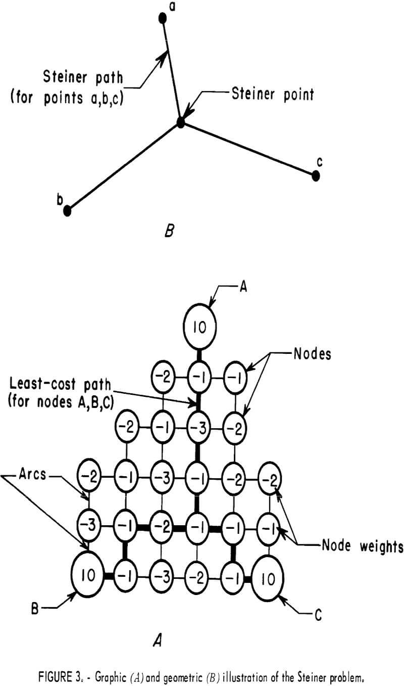
network is an often-pursued problem in network theory; however, there is no standard algorithm available to solve the problem. Approaching the mining problem in terms of a network gives flexibility of using any combination of block configurations and ease of problem expression and manipulation with existing computational techniques.
Of particular interest in the mining problem is that there may exist a node belonging to the set of negatively weighted nodes, which, if forced into the solution set, will yield a better solution by acting as a common junction between three or more positively weighted node groups. Because this node is similar in many respects to a Steiner point defined in the classical Steiner problem, this type node will be referred to as a Steiner node. In brief, the Steiner problem may be stated as: Find the path of minimal geometric length connecting m points in a plane. Figure 3-B illustrates a least-length or Steiner path for three points in a plane. Figure 3-A is analogous to the general Steiner problem defined on a plane. The general Steiner problem was not pursued because (1) generally, an ore zone may be difficult and misleading to be represented as a geometric point, (2) generally, ore deposits do not occur in planes, and (3) Cockayne (4) states that available computer codes are limited to problems of 20 to 30 points.
Some additional terms are needed to clearly define the mining problem totally in terms of a network. A graph G = G(V, Γ) may be simply defined as consisting of a set of nodes, V = {v1 , v2 vm }, and a set of arcs, Γ = [b1, b2 bn}. In addition, it is sufficient to define a set of weights, {w(vi)}, such that w(vi) w(vg) are ≤ 0 and w(Vg+l) w(Vm) > 0. An arc, bi, denotes a line segment connecting some node, Vk , to another node, Vj , or more simply as (k, j). In terms of the mining problem, there is no need to describe a directed graph, therefore, (i,j) = (j,i). Any two nodes will be called adjacent if they are joined by a single arc. A path, πij, may then be defined as a sequence of ordered nodes and arcs as (vi, (i,s), vs (tj),vj). A path as used in this paper does not contain any cycles; that is, for the sequence of nodes in the path, there is no repetition of any node. A connected graph is defined as a graph where at least one path exists from any arbitrary set of nodes to all others in the graph. Finally, a tree is defined as a connected graph having no cycles. The nearest neighbor to some node, i, as used in this report, will be a single node, j, from a set of possible nodes having the least-cost path from node i.
Problem Formulation
The general subsurface mining problem defined on a set of blocks may be simply stated as find
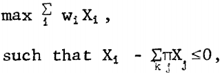
where πjXj represents the product of a sequence of geometrically adjacent blocks leading from block i to the surface and Σk represents the sum of all possible sequences,
and Xi = l if block i is mined
0 if block i is not mined
and wi = weight assigned to block i.
Mathematically this set of equations defines the general subsurface problem of concern in this paper; however, practically it would be extremely difficult to formulate or solve a problem in this form even for small problems.
Considerable time and effort was taken to model this relationship by some standard mathematical programming techniques. Attempts to formulate the problem as both a linear and integer problem were not truly successful from the viewpoint of the general problem just defined. Difficulties arise in defining a set of linear constraints. It is a well-known fact that for practical-size problems with nonlinear constraints finding computationally efficient computer codes is a problem that must be considered. The need for an integer solution plus the need for comparing alternative block sequences make this problem extremely difficult to formulate in general terms. Computational efficiency of known integer codes decreases at a rate significantly faster than a comparable increase in the size of the problem.
Because no efficient mathematical programming technique was found, a network approach was pursued. In terms of a network, the ultimate underground mining plan may be simply stated as: Find a connected subgraph, call it G0, such that the weights belonging to G0 is a maximum. It is also a generally recognized fact that there are many computationally efficient computer codes available to solve large network related problems; for example, the shortest route, the maximum spanning tree, and the maximum flow.
Solution Algorithm
An algorithm for finding the ultimate subsurface mining configuration is given in this section and followed by a detailed description of the least-cost path algorithm which is a fundamental part of the solution algorithm. The least-cost path problem is comparable to the shortest route problem. Much work has been done in the development of algorithms for the shortest route problem. The algorithm for the mining problem is in two parts, phases 1 and 2.
Phase 1 of the solution algorithm begins by collecting all of the positively weighted nodes (blocks), which are adjacent into a single node having as its weight the sum of the weights of all its individual members. If no positive nodes exist or if only one is found, the algorithm terminates. If two or more positive nodes are found, phase 1 then proceeds by taking the maximum from the newly found disjoint positive nodes and finding its nearest positive neighbor using a least-cost path algorithm. If the weight of the two disjoint positively weighted nodes plus the least-cost path is strictly greater than the starting node weight, the algorithm proceeds by finding the least-cost path to a positive neighbor from the combined subgraph consisting of the two positive nodes plus the least-cost path. The phase 1 algorithm continues until no additional nodes from the set of positive nodes can be brought into a connected set of nodes. Phase 1 will give a good solution; however, in general, it may not be optimal. The necessary conditions for a mathematically optimal solution will be discussed in detail under “Algorithm Structure.” For phase 1, a computer code was developed and is discussed under “Computational Experience. ”
An upper bound on the value of the ultimate mine layout would be the sum of all the positive nodes and a lower bound would be zero, which implies the absence of any positive blocks. These facts could be useful in deciding when to terminate the algorithm. For example, if the upper bound is not sufficiently large to meet corporate objectives, the project could be abandoned immediately without further study.
Phase 2 describes a procedure by which a user may try to improve upon the solution resulting from phase 1 through the introduction of Steiner nodes. A Steiner node may be simply thought of as a node, which, if mined, would result in a negative return; however, if by mining that particular node it is possible to use this node as a common intersection of development entries (drifts) for three or more disjoint potential ore zones, then the overall mining costs would be reduced.
The solution algorithm assumes the problem to be defined as a general network as previously described. The mining problem was defined in terms of a general network so that a general algorithm could be found that will work for any number of different block configurations.
General Algorithm
In this section the algorithm used to solve the general ultimate subsurface mine problem is amplified. For definition of terms, see appendix A.
Phase 1:
Step 0 Set AMAX = 0, set ATEMP = 0, set S = 0.
Step 1 Collect all vertices from the set {(vg+1) (vm)}, which are adjacent, into P disjoint sets and form the set {(vj) | j = 1 P]. Set T0 = Ω. If P = 0, stop; the set {(vj) for all j} empty. If P = 1, stop; the optimal solution is w(vl). Otherwise continue. Set Lj = 0 for j = 1 P.
Step 2 Set TEMP = 0, set i = 1.
Step 3 If Lj = ∞ for all j, go to phase 2. Find q such that w(vq) = max [w(vj ) |_Lj = 0, j = 1 p} = TEMP. Set Lq = ∞, Ti = Vq and T = Ω.
Step 4 Find least-cost path 1 (πjb) from Ti + T to nearest positive disjoint neighbor k such that node s is adjacent to tree, Ti + T, and node j is adjacent to node k. If | l(πjb) | > TEMP, go to 7.
Step 5 If TEMP + l(πjb) > TEMP, set TEMP = TEMP + l(πjb) + w(vk) and set Lk = ∞ and go to step 6. Otherwise set T = T + πkb and go back to step 4.
Step 6 Increment i; i = i + 1. Set Ti = Ti-l + πjb + vk. If Lj = ∞ for all j, go to step 7. Otherwise set T = Ω and go back to step 4.
Step 7 If TEMP ≥ ATEMP, set ATEMP = TEMP and set T0 = Ti. Go to step 2.
Phase 2 allows the user to force any node not present in the solution found in phase 1 into the solution set.
Phase 2:
Step 1 If S = 0, go to step 2. Otherwise set ATEMP = ATEMP – M x S. If ATEMP ≥ AMAX, set AMAX = ATEMP and T = T0.
Step 2 Option to stop at this iteration.
Step 3 Out of the set of nodes, such that w(vt) ≤ 0, select a set of Steiner nodes t = 1 S, S ≤ P – 2. Set w(vt) = w(vt) + M, t = 1 S, and add vt to the set of positive nodes. Go to phase 1, step 2.
Using good perceptual judgment at this point can speed convergence of a realistic problem by helping to reduce unnecessary computational time which could be introduced by an enumerative selection of Steiner nodes.
Least-Cost Path Algorithm
A detailed labeling algorithm is given for finding the least-cost path from any node, q, to every other node, t, in a network, given that all node weights are negative and weights on the arcs are all zero. The algorithm is essentially a dynamic programming approach very similar to that discussed by Dreyfus. The major difference is the fact that the weights are defined exclusively on the nodes as opposed to the arcs. This, in fact, simplifies the general approach suggested by Dreyfus. In terms of the general algorithm, a set of nodes {q} would represent a set of nodes in a tree.
Algorithm:
Step 1 Label a set of source nodes {q} as L (-,0).
Step 2 Find an unlabeled node t and a labeled node s such that l(πqt) = min {l(πsq) + w(vt ) for all nodes s and t such that node t is unlabeled and adjacent to a labeled node}.
Step 3 Label node t as L(s,l(πtq).
Step 4 Does an unlabeled node exist? If yes, go to step 2. Otherwise, stop.
Note: q and s are indexes for labeled nodes and t is for the unlabeled. Also, for the label, L(s,l(πqt), s denotes the adjacent node from which node t is labeled and l (πqt) denotes the best path from node t to node q.
Discussion of Solution Algorithm
Sample Problem
The following problems were constructed to illustrate how the algorithm works and under what conditions the algorithm can lead to nonoptimal solutions. The illustrations are overly simplistic and in most cases the optimal solution is obvious. In a realistic problem, however, the optimal solution will not be obvious.
Figure 4-A gives a network equivalent to a mining problem having three disjoint ore pods (A,B,C) which would yield a payoff of 10 units each if they could be mined. In addition, node G is adjacent to node C and yields a value of one unit. For example, if node G were exposed to the surface, then nodes C and G could be mined at a combined payoff of 11 units because they are adjacent. In the winning of nodes A and/or B, it is possible to proceed from C by three different paths all of which contain negatively weighted nodes. Obviously then, the user wishes to pick the path that yields the least-cost for the potential gain. For figure 4-A the optimal solution is, obviously, equivalent to the node blocks A through G having a total weight of 25 units.
For the problem in figure 4-A the algorithm would proceed as follows beginning at phase 1: Step 0, set AMAX, ATEMP, and S = 0 and move to step 1. For step 1 combine the node weights C and G and form a single node. Call it node C. Figure 4-B will then become equivalent to the network in figure 4-A where no two adjacent positively weighted nodes exist. P is equal to 3 or, in this problem, let j = A, B, and C. Set LA,LB,LC.=0, i = l, and TEMP = 0 in step 2. In step 3, q = C because the maximum of {w(vA), w(vB), w(vc)} is w(vc); therefore, set TEMP = 11. Now set Lc = ∞. In step 4 the least-cost path from node C to either node A or B would result in choosing node E, which yields a net of 18 units. The nearest neighbor, k, then is node B. Since | l(πEE)| = 3, which is less than 11. Go to step 5. In step 5 because 18 > TEMP (which was set = 11 in step 3), set LB = ∞, and go to step 6. Increment i (i = 1 + 1 = 2) and set T2 = [C, E, B,} and go to step 4. The least-cost path from T2 to the remaining disjoint positively weighted node
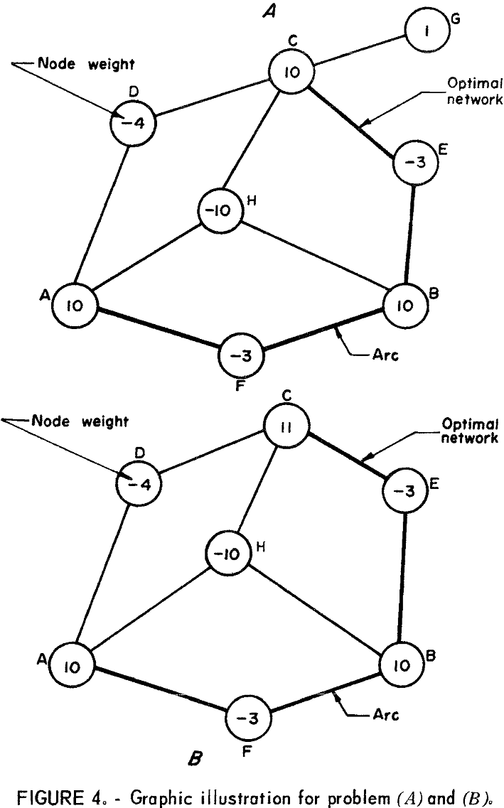
(k = A) would be the node [A], which yields a net of 18 + (10 – 3) =25, which is greater than TEMP. Therefore in step 5 let LA = ∞ and proceed to step 6, to step 7, to step 2 and finally to step 3 where LA, LB, LC, = ∞ which terminates phase 1 part of the algorithm. If it were desirable to force the solution through the Steiner node H (phase 2), a large positive value, M, would be added to the node weight of H, which in this instance would be -10 + M. Returning to step 1, phase 1, and passing through the phase 1 algorithm again will yield a net of 21 + M. Subtracting M from 21 + M gives an answer of 21, which would be <25. Thus for this problem, figure 4-15, because there is only one possible Steiner node, the solution, {C, E, B, F, A}, is optimal.
To illustrate the two possible alternative kinds of things that can cause the phase 1 to yield a mathematically nonoptimal answer, refer to figure 5. Without the introduction of a Steiner node, the problem in figure 5-A would result in a solution, similar to that found in figure 4-B, yielding a weight of 25; however, for this problem, the network {H, A, B, C} yields 26 units, which is >25. By adding a large positive weight, M, to the node weight of H (-5 + M) the phase 1 algorithm would yield 26 + M, less M is 26, which is >25. Thus the optimal graph G0 = [H, A, B, C] has a total weight of 26. Figure 5-B illustrates a situation where the positive disjoint nodes are not of sufficient weight to allow the algorithm to yield an optimal answer without forcing the Steiner node into the solution. Of interest is that for the phase 1 algorithm not to yield an optimal solution, the optimal graph G0 must contain a Steiner node. Detection of Steiner nodes is left to the user in phase 2. However, the author feels that in a real problem it should not be
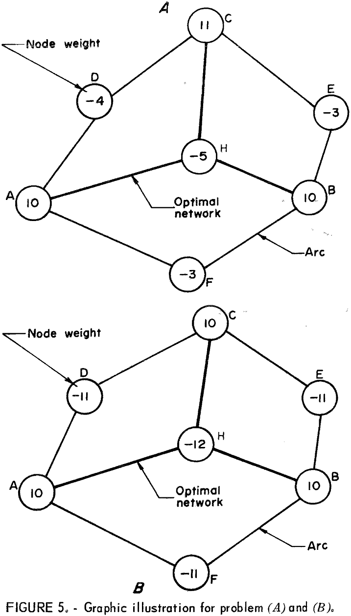
too difficult to locate the most obvious location of Steiner nodes. Mathematically, then, the described algorithm will yield an optimal given that no Steiner-type nodes need be introduced.
Algorithm Structure
Given that we have an optimal graph, G0, to the ultimate mining layout previously stated on a network, there are several characteristics that the solution will have. They are as follows:
Statement 1-All adjacent positive nodes i and j will either be completely within the optimal solution or completely outside.
Statement 2-Considering only the positive disjoint nodes, vi, such that i=l P and an absence of Steiner nodes, the optimal path connecting these P disjoint nodes must be a maximum spanning tree.
Statement 3-There will be, at most, P-2 Steiner nodes for a problem with P positive disjoint nodes vi.
Statement 1 may easily be shown to be true. If we assume that two adjacent positive weighted nodes are not both in the optimal solution, the solution is obviously not optimal because a better solution could be found by simply including the adjacent node not presently in the solution set.
The second statement implies that the optimal solution, given no Steiner nodes, is a maximal spanning tree. First, the optimal must be a tree because if it were not, at least one node (and its incident arcs) having a negative weight could be dropped without destroying the connectivity of the nodes in the set {vi}, thus a better solution is possible. A spanning tree is here defined as the tree consisting of only the negatively weighted nodes connecting all of the nodes belonging to the set {vi}. Secondly, given an optimal spanning tree, G0, assume a path not found in the optimal tree between some pair of nodes in the set {vj}, which is better than some path in G0. This assumed path together with some set of arcs and nodes in G0 will form a cycle. The length of the assumed path must be less negative than those paths connecting paired nodes in the set {vi} if it is to lead to an improvement. Because this path is not in G0, it must be strictly greater than the other possible paths. Therefore, by contradiction of the assumption, G0 must be a maximal spanning tree.
Repeated usage of the least-cost algorithm constructs a stage-wise spanning tree for the set of disjoint positively weighted nodes. However, it is possible that the general algorithm will construct a forest (more than one tree) in which case the maximum graph, G0, will occur within some subset of vi type nodes. In other words, the general algorithm terminates whenever the spanning tree for some subset results in a negative contribution. In this situation the algorithm simply picks the maximum from the subset of spanning trees.
In terms of the general problem, the algorithm itself may introduce Steiner nodes. Therefore, statement 2 is not a strong statement. The usefulness of this statement given that all of the Steiner type nodes can be defined is that the algorithm herein (phase 1) will yield an optimal solution.
The third statement can also be easily shown to be true because the number of arcs incident to Steiner nodes must be at least three. Any more than three will reduce the number of possible Steiner nodes for a fixed number of P disjoint positively weighted nodes. The total number of Steiner nodes S must be strictly less than Sx, which will be here defined as the maximum number for a fixed number P of positively weighted nodes. Therefore, using the basic properties of a tree the total number of arcs may be given as 3Sx + P/2, which is equivalent to Sx + P-l nodes. Setting these equal to each other and solving for Sx in terms of P yields Sx=P-2; therefore, in general the number of possible Steiner nodes S in any problem must be less than or equal P-2. This completes the proof.
The least-cost path algorithm, upon which the ultimate underground problem is based, is similar to the labeling algorithm first described by Dijkstra, Whiting, and Hillier as quoted by Dreyfus. The primary difference between what is written by Dreyfus and least-cost path algorithm described herein is how the weights are defined. For the mining problem all weights are defined on the nodes as opposed to the arcs for the standard shortest route algorithm. In addition, Dreyfus states the shortest route problem is a minimization technique compared with a maximization for the mining problem. He, also, defines positively weighted arcs (it is sufficient to have no negative cycles) as essentially a set of negatively weighted nodes in the mining problem.
The labeling algorithm, described by Dreyfus, works with two mutually exclusive and totally exhaustive sets of nodes, either permanently labeled or temporarily labeled nodes. At each iteration of the labeling algorithm, one node is transferred to the permanently labeled set and the algorithm terminates when there are no more nodes left in the temporary set. The algorithm thus constructs a maximal spanning tree.
Proof of the least-cost labeling algorithm, as used in this paper, may be made by induction. It is necessary to remember that the least-cost algorithm is defined completely on a set of negatively weighted nodes. At any stage in the least-cost algorithm the nodes may be classified into two sets-one containing the labeled set of nodes and another containing all the unlabeled sets
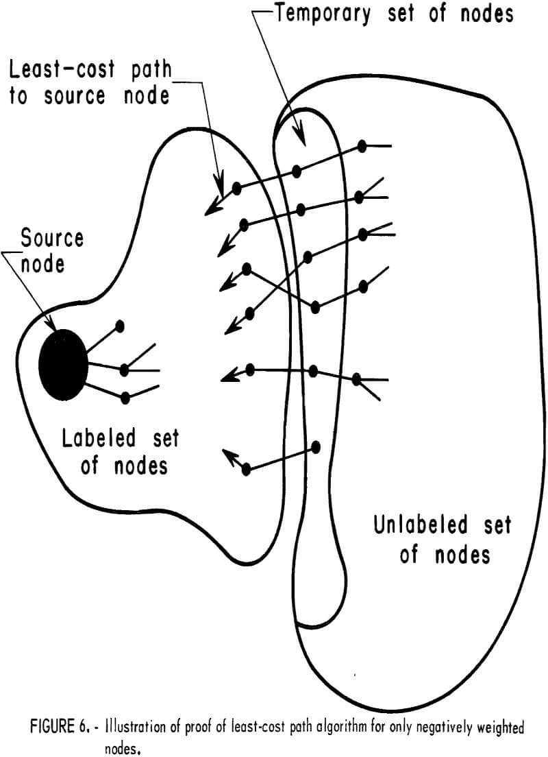
of nodes (fig. 6). Labeled nodes are those for which a least-cost has been defined to a source node. For all those nodes in the unlabeled set adjacent to the labeled set, it is possible to find the least-cost distance to the source node such that all nodes in the least-cost path will be in the labeled set except one which will be in the unlabeled set. This distance is only temporary. Obviously, then the node in the unlabeled set which has the minimum temporary distance may be transferred to the labeled set. For if it is assumed that there exists a better less costly path, it would have to exist as a path in the unlabeled set. Because all of the nodes are negatively weighted, this path does not exist.
Implementation
Application to a Coal Property
Setting up a problem to be solved using this basic approach demands a certain amount of innovation on behalf of the user. For example, a user might wish to allocate to a block having length, width, and depth a portion of the unmined block for ground support. In terms of the network equivalent, this will be represented by a node weight. In the event of an uneconomic block (negative weight), the user might choose to consider only the cost of driving development entries through the block. On the other hand, a user might wish to define a block as a minable unit equivalent to net worth or a mine support unit and assign a large negative cost. The block weight need not be a cost; it could be the risk of roof fall in a particular block and the design engineer wishes to find the best development entry layout between two or more points having the least chance of a roof fall.
An illustrative problem is given in figure 7 for a hypothetical coal mine. For this illustration the problem is contained entirely within the coal seam for clarity of presentation; however, a three-dimensional model might be much more realistic. The square is a realistic block configuration, as a coal seam is normally mined consistent with a rectilinear movement. For a coal seam the coordinate directions would, more than likely, be structured so that they coincide with butts and cleats (planes of weakness) in the coal seam, but not necessarily. This would be dependent upon ground control problems. The block size has been taken equal to 800 by 800 feet with block weight equivalent to the profit or loss to the mining company. Block weights might be entirely different for another company. A block in which the net worth is less than zero for this problem indicates that as a minimum requirement, an access (set of entries) be driven through the block. This assumes that the cost of mining in either direction is the same, whereas, in reality this might not be precisely true.
If there does not exist a natural access to the surface, as is the situation for many mineral deposits, it would be necessary to assign some subset of surface blocks a large positive weight. This would force whatever material that could be economically mined to be connected to the surface. In addition, if it were desirable for some reason to force the mine through a particular set of blocks, this could be accomplished by adding an artificial block weight to those blocks, which would be subtracted later. To force access to the
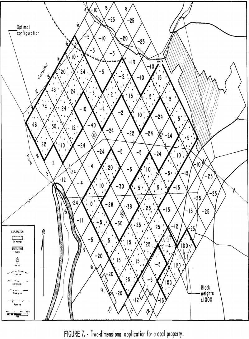
surface in this problem, blocks (columns 4 through 6 in row 12) were given an artificial weight equal to $100,000 each. From a practical viewpoint these blocks might be considered as potential sites of a mine plant or mine portal. For this problem three oil wells are located in the coal seam of interest. The cost of mining through these blocks considered such costs as plugging the wells or the uncertainty of the well location within the block. The Coal Mine Safety Act of 1969 specifies that a barrier of 300 feet must be maintained around an active or inactive oil or gas well. This fact is reflected in the weights of the blocks within the neighborhood of oil wells. The physical and chemical properties of the coal, ownership, nearness to powerlines, location of old mine workings, chemical and physical properties of the coal, etc., all had a bearing on the assigned block weight. Results of this particular problem are given in appendix B.
Of interest in this particular problem is that the results would not be consistent with one’s intuitive concepts of mine layout. However, by strategically reassigning block weights and repetitive use of algorithm herein described, the user could study many alternative plans at a minimal cost. Varying the block size would allow the user to compare different methods of mining.
Computational Experience
A computer program was developed in Fortran IV for a Bureau of Mines Burroughs 5500 in Denver. A copy of the computer program is included in appendix C. The computer program is written to handle a problem with a maximum of 6,000 blocks. The upper bound on the problem size is only dependent upon the size of core available. The processing time was found to be primarily dependent upon the total number of blocks, and the number and distribution of disjoint positive blocks. Table 1 gives the results for four different size problems.

Input requirements consist primarily of the block weights, problem parameter, problem title, and the output needs. Input must be prepared in the following sequence and contain the following information:
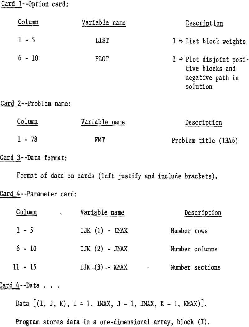
Output is under program control to the extent that the block weights may be printed or suppressed as can the plot of the solution. Included in appendix B is a copy of the output for the sample problem given in figure 6.
Conclusions and Extensions
The algorithm defined in this report offers the mining engineer a simple technique for long-range mine planning. In addition through the use of a computer program, the technique was demonstrated to be programable for solving an orthogonal, three-dimensional set of blocks and reasonably efficient for those problems tested. In view of the lack of comparable studies, it is exceedingly difficult to fairly evaluate this work; however, the author is extremely optimistic as to the potential of this study.
Such factors as time value of money can be taken into account by making allowance in the calculation of block weights. This forces the individual to design for the long term consistent with conservation of resources. In mining, development costs generally are higher than production costs, and, therefore, the faster a mine can be brought into production, the greater will be its present worth. However, forcing a mine into early production may have the effect of increasing future development costs. In fact, favoring production at the expense of development may lead to the loss of a potential resource.
The general procedure given in this paper will have application to a wide range of subsurface mining-type problems. Interpretation of block weights could be other than a dollar cost; for example, it could represent a risk or some estimate of hazard to be encountered in a particular block. Thereby, the algorithm could be used to study possible escape routes when a disaster has occurred at some place in the mine network.
This general algorithm is constrained in that no account is made for the direction in which a block is to be extracted. For example, it would be less costly to extract a block from the bottom as opposed to extracting it from the top or side. In fact, mining costs might be closely related to local fracture or joint patterns. The problem of mining cost might be best accomplished by assigning arc weights in addition to the node weights, allowing the arc weights to represent the mining cost of mining blocks j from i and the node weight, the block mineral worth.
A problem presented by the orthogonal network as developed herein for the computer program is that the alternatives for moving from block to block is constrained to an orthogonal movement (forwards and back, left or right, up or down). Without the loss of generality specifically with respect to the computer program the basic network could be modified to allow a user to move diagonally across blocks or possibly even skip particular blocks if the strategy for block jumping could be generalized. Use of other basic geometric configurations would also give the user more flexibility. Use of hexagons in a two-dimensional space, for example, allows the user six degrees of freedom to advance from a particular block compared with only four in a plane for which the computer program was written. Figure 2 and the book by Cole and King indicate other possible geometries. The importance of using an orthogonal set of blocks lies in the fact that because of the highly structured resulting network, there is no need to store an elaborate arc incident matrix.
Much can be done in defining a strategy for designing a production scheduling sequence for a given ore zone or a safe pillar configuration for a given mine by modifying the basic orthogonal network presented in this paper.
The reader should be alerted that the mining problem should be investigated as a total system as the ultimate layout is but one small problem; however, due to the complexity of the underground problem, and the usual limited data base available on a property prior to mining, a piecemeal approach does seem appropriate dependent upon design requirements. For example, facility location and scheduling problems might or might not be of particular importance depending upon the particular property. This approach gives the minerals industry a tool for studying alternatives to mine layout; it does not specifically answer to the facility location, or to the general problem of mine layout with respect to development and production faces, nor does it answer to the problem of scheduling a property to meet production demands and milling constraints.
