Its purpose is to highlight the things that have been accomplished by the mill designers to lighten the load for the maintenance superintendent and to reduce the overall costs for the plant operator. The complexity of plant design, the civil and structural engineering problems encountered when the satisfactory maintenance layout is accomplished are appreciated, and the writer is fully aware of the complexities of these problems. However, it is not the purpose of this particular paper to dwell upon these problems, nor to emphasize or de-emphasize the problems of the civil, mechanical and electrical engineers. It is simply that the paper will attempt to review what these people have accomplished in spite of the many technical problems.
Maintenance Areas
The old-timer repaired most pieces of equipment in place in the area available, and if additional space was needed it was arranged to transport the part or the piece of equipment to some sort of a central shop. Except for the most sophisticated plant, there was no allowance for a shop or a maintenance area as such in any plant. In addition, consideration was not given to laydown and maintenance areas adjacent to the larger pieces of equipment. There were a few exceptions to this; however, most of these exceptions were found in crushing plants.
The inclusion of a maintenance area in most mills is now considered a must. These areas vary in size, but in general are sufficiently large to allow the mechanical crews to perform routine tasks on welding, grinding and simpler renovation of various pieces of mechanical gear. This eliminates a considerable amount of transportation and rigging problems, allows for the maintenance of a certain size mechanical crew within the mill building at all times, and allows the operator to keep some contact with maintenance procedures.
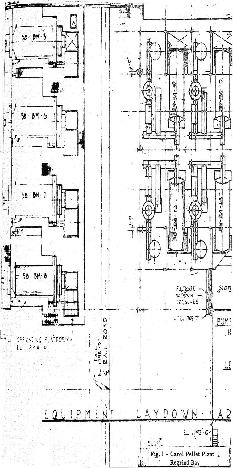
The long access way in front of the mill not only provides space for certain maintenance tasks, but also again facilitates the transportation and allows for use of mobile handling equipment as well as conventional cranes. This bay is one of the best examples in the industry for efficiency of transportation for plant maintenance.
In the current approach to mill operation it is necessary to remove many units from the mill circuits and replace them with a complete unit during the scheduled maintenance period. The unit replacement concept has gained favor each year as it allows for a rapid replacement rather than the repair in-place of a piece of equipment; in many instances, this replacement can be accomplished more rapidly than the repair. This means that the plant down time can be kept at a minimum, and this is important because of the large capital investments.
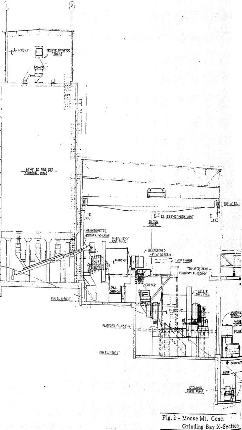
The other type of maintenance area that is now considered a must in adequately designed mills is the maintenance area around major pieces of equipment. There are certain pieces of equipment such as grinding mills that cannot be easily removed. There are instances where these mills are replaced with units, but this is the exception rather than the rule. It is now common practice around these heavier pieces of equipment to allow for a sufficient laydown to provide for ready access and laydown during maintenance periods.
Equipment Accessibility
At one time if the equipment was in the flow stream so that the flow of pulp did not cause excessive abrasion upon transfer into this particular piece of equipment, this met the main requirement for layout, in the pre-war period, of course, slurry pumping was a serious problem and very bothersome. Therefore, much emphasis was placed on gravity in line flows to accommodate the flow of the material. These principles still exist. In other words, material flow should not be sacrificed and slurry pumps should not be used indiscriminately. However, there are other factors that must be considered.
Once the decision has been made about unit replacement versus repair in place, the design criteria can be established. If it is a unit replacement then there must be adequate clearance for removal of the equipment from its location easily, and there must be a suitable handling device to transport the equipment auxiliaries and/or launders and sumps from their operating location to the repair area.
An example of good planning for accessibility is shown in Figure 5 which is a detail of the grinding bay of the Carol pelletizing plant. It can be noted that the slurry pumps are located to allow complete access around the pumps and there is an allowance for a quick disconnect of the pump from the sump. In addition, there is crane accessibility overhead through the hatch if this is desired. Also, there is readily accessibility for mobile equipment to approach the equipment and remove either the entire piece of equipment or the individual replacement parts.
Maintenance Aids
The well designed plant of today not only locates the equipment properly, provides maintenance areas, roadways and overhead cranes, but, in addition, during the detailed design of the plant the designer makes every effort to provide for various maintenance aids that will increase the efficiency of the maintenance manhour and consequently improve the overall efficiency of the plant. These maintenance aids are varied and multiple in nature.
The most common ones are establishing hooks and eyes above the equipment to allow for the utilization of hoists, as well as certain location of hooks along the walls of various buildings to allow for movement and easy shifting of a piece of equipment.
The good mill designer now locates the equipment and then works up the necessary maintenance aids to allow these items to be a permanent part of the plant. This contribution by the mill designer has reduced maintenance cost in some of the newer plants by as much as 15 to 20 percent.


