Table of Contents
Filter Presses
Filter presses are batch units that use higher than atmospheric pressures and a series of filter plates to separate the solids from the liquid. They are also called pressure, plate-and-frame, or press filters. Although this type of device is well known, it has had little attention or application in the U.S. minerals industry because of its batch process nature, high capital cost, and associated high labor requirements. In spite of these drawbacks, the filter press should receive close attention because of its separation efficiency.
There are two types of filter press systems available—the high-pressure system and the low-pressure system. The first type uses a pressure of up to 225 lb/in², while the second type uses a maximum pressure of 100 lb/in². Research has shown that the higher filter pressure does not provide a significant benefit over the lower pressure unit with respect to dryer filter cakes or shorter cycles on chemically conditioned slurries.
Pressure filtration is a fairly simple process. Initially, the slurry is chemically treated and then pumped into the press (fig. 15). The filtrate flow from a large press can be 10,000 to 15,000 gal/h, so that this part of the cycle is often called the fast fill. During this phase, the cake chambers of the filter press collect the major amount of slurry solids. As the chambers become progressively filled with solids, the pressure inside the press rises and the filtrate flow rapidly decreases. This portion of the cycle is the cake consolidation
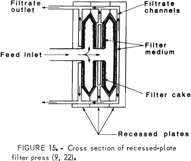
phase, where slurry solids are being forced under pressure into the cake chambers. This compacting action displaces more water from the loosely formed slurry cake and enables the press to produce harder and drier cakes than other means of dewatering.
At a predetermined low-flow condition, pumping is stopped and the feed holes that carried the unconsolidated sludge into the press are blown clear. The stack of filter plates is undamped, and the individual plates are mechanically separated, allowing the filter cake between adjacent plates to drop out of the chambers. The cakes then fall against breaker bars that reduce them to a convenient size before they are transported for final disposal.
Although pressure filtration is a batch process, a series of presses can be organized to work in a semicontinuous operation. This is done by having one press being filled, while a second is being airblown and a third is being unloaded or waiting to be filled again.
Filter presses find wide application in the process industries for the separation of slow-settling solids from liquids when the solids content is 1 to 10 pct and the filterability is poor. The use of these presses depends mainly on the particle size and on the quantity of solids in the slurry feed. The capacity of the press is dependent on such factors as the characteristics of the material being filtered, operating temperature, pressure, filter medium being used, and type and size of filter press. There is no mathematical formula or scientific method for determining the exact filtration capabilities or rates. The most reliable method is to use past experience or records and to make controlled tests on laboratory-sized equipment.
Advantages and Disadvantages of Filter Presses
Filter presses are efficient at dewatering very fine grained solids such as slimes and consume only moderate amounts of power during their operation. Labor requirements are high, however, and the batch operation may be a limitation in some facilities. Chemical pretreatment is frequently needed to obtain the necessary solids capture. Also, large space requirements and the possible need to treat the decant liquors may restrict use. Despite these problems, a well-designed system of multiple filter presses might be the answer to difficult slime dewatering problems.
Continuous Pressure Filters
Although they are not well known, some pressure filters are available that work continuously. These units operate similarly to a drum or disk vacuum filter, except that the entire mechanism is enclosed in a pressurized tank. The cake is removed from the filter medium by a blade under super atmospheric pressure. The dislodged cake is throttled out of the tank to atmospheric pressure by a self-sealing screw conveyor or a series of receivers and pressure locks.
The operating pressure in these machines is normally 100 lb/in² with a pressure drop of 40 lb/in² across the filter medium. Filter areas from 4 to 700 ft² are available. The cost of continuous pressure filters can be two to four times that of a vacuum filtration unit having the same filter area.
Continuous pressure filters are advantageous because they work continuously and do not require close operator supervision. These units are also capable of much higher filtration rates for low-compressibility solids than are vacuum filters. There are drawbacks, too, because these machines are mechanically complex, do not allow access for any maintenance during operation, and have problems with lubrication. As mentioned before, these units are more expensive than similarly sized vacuum filters.
Belt Filter Presses
Belt filter presses have been manufactured in Europe since the midsixties and have been used mostly in pulp or paper plants and for sewage sludge dewatering. Only in the last several years have these machines been used by the minerals industry. Experimental work with the belt press indicates that this machine produces a drier cake with lower polymer consumption than centrifuges or similar dewatering devices. The belt press cake also has a relatively high shear strength, which is Important if the cake is to be transported to a waste dump.
The belt filtration process is composed of three operational stages: chemical conditioning of the feed slurry, gravity drainage to a nonfluid consistency, and compaction of the dewatered solids. Figure 16 depicts a simple belt press and shows the location of the three stages. Although present-day belt presses may be very complex pieces of equipment, they follow the same concepts indicated in this figure. Good chemical conditioning is of primary importance to successful and consistent dewatering by the belt filter press. The recent developments in high-grade polymeric reagents have encouraged the development of belt presses to their present performance levels.
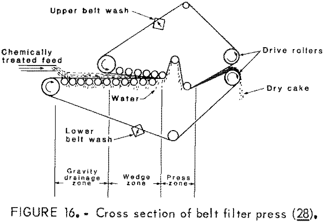
The first stage in belt press dewatering is to add a flocculating agent to the slurry in a conditioning zone. The resultant mixture must be allowed to set under low shear conditions to allow flocculation to take place. If this mixture is disturbed during flocculation, more chemical agents may be needed to obtain the necessary degree of flocculation and any economic advantage will be lost. The conditioning zone should have an adjustable residence time which can be increased or decreased to suit the slurry being treated. Correct conditioning liberates the free water originally contained in the slurry and also facilitates the capture of the finest particles present by causing them to flocculate with the larger particles. This is necessary since water removal will be carried out on belts whose openings are larger than the smallest slurry particles.
The next stage after chemical conditioning is gravity dewatering, which allows the free water to drain from the solid particles. The slope of the belt will normally be set at 5° to 15° from horizontal to assure proper distribution of the solids across the belt as the water is separated from the slurry. At the end of the drainage section, the slurry will lose about 50 pct of its free water. At this time, the formation of an even surface cake is essential for the successful completion of the following stage in the cycle. The even surface prevents uneven belt tension or distortion, and the rigidity of the semicake enhances distribution through the process.
Following the gravity dewatering stage, the semicake is sandwiched between the carrying belt below and the covering belt above. The semicake is squeezed between the two belts and subjected to flexing in opposite directions as it passes around various rollers. This action increases water release and allows greater compaction of the cake. At least one manufacturer has developed a high-performance belt press that has a low and a high belt pressure stage. This machine is basically the same as other belt presses except that in the high-pressure stage, an additional belt is added to increase the pressure on the solids cake and remove more water.
Finally, the dried cake passes from between the two belts and is carried away from the machine by truck or conveyor belt for ultimate disposal.
The material and construction of the filter belts themselves are very important. Belt filter presses do not utilize the belt-fabric as a filter medium but as a support for the self-filtering solid-liquid mass. The mesh size of the belt fabric is not critical because very large flocs will be produced by the polyelectrolytes in the first stage of operation. Texture, however, is a significant feature of the belts because it influences the adhesion of the cake to the belt and the physical strength of the belt. Currently, the available belts are those used in the papermaking industry, although a wider variety of special-purpose woven belts are becoming available. Most belts are woven from polyester monofilament, and many weaving patterns are available.
A major problem with the belt press is that an uneven layer of sludge causes the belt to deviate from, the desired tracking line. This occurs because the filter belts usually have short lengths and widths. Direct side pressure should not be used because guide rollers would cause serious wear on the edges of the belt. One system that has been devised uses a delicately balanced sensor flap which rests lightly on the edge of the belt. This flap is attached to the spindle of a rotary directional fluid-flow control valve. Displacement of this valve causes hydraulic fluid to flow to either one or the other end of a cylinder which supports one end of the belt roller. The cylinder’s movement causes the roller to slew across the line of travel of the belt, and belt tracking is induced rather than forced.
The openings in the belt are easily plugged by the solids particles so the belt must be washed continuously. The contamination of these perforations depends on the belt tension, pressure on the cake, complexity of belt weave, type of sludge being treated, and quantity and type of polyelectrolyte being used. Washing is done using water; however, the volume and pressure used vary from manufacturer to manufacturer. The current trend is to recycle the filtrate as belt washing water. This is satisfactory if the spray system is well designed to allow cleaning in the event of a blockage. At low solids concentrations the volume of filtrate produced will be adequate for belt washing.
Advantages and Disadvantages of Belt Filter Presses
Belt filter presses have several advantages, which include—
- Continuous operation
- Low power consumption, as low as 3.7 kW according to one manufacturer
- Low consumption of chemical additives; one manufacturer claims his unit uses only 25 to 50 pct that used by centrifuges for some applications.
The disadvantages of belt filter presses include—
- Problems with proper belt tracking
- Shortened belt life if very coarse solids are dewatered
- Difficulty in dewatering slurries having a very low solids content
Vacuum Filtration Equipment
Vacuum filtration equipment has been in use in this country for over 100 yr, and continuous vacuum machines represent the most prevalent type of filtration equipment seen in the mineral industry today. Their simple operation and need for a minimum of auxiliary equipment has made them popular for solid-liquid separation in a variety of industrial applications.
Continuous vacuum filters separate the solids and liquid in a slurry by placing the filter in the slurry and applying suction behind the filter so that the water and solids are drawn to it. The solids are collected on the filtration surface, while the water is drawn through the filter and separated from the solids. The particles accumulate to form a cake on the filtering surface that is gradually lifted from the slurry. The cake is removed from the filter by various means, and the filter is returned to the slurry to repeat the process.
Vacuum filters must have several items of auxiliary equipment in order to function properly. An agitator is needed to keep the slurry solids in suspension until they are drawn to the filter medium. A vacuum pump provides the subatmospheric pressure to draw the liquid through the filter. A receiver with a barometric leg is located between the filter and the vacuum pump and separates the liquid from air drawn through the filter. Last, a filtrate pump removes the liquid from the receiver and forces it to the disposal point or back into the circuit for reuse.
The following sections describe the filtration equipment found in the minerals industry.
Drum Vacuum Filters
Drum vacuum filters are probably the most common type of continuous vacuum filters in use. They consist of a horizontal cylinder or drum whose circumference holds the filter medium. The drum rotates in a slurry tank, and a vacuum inside the drum draws the liquid through the unit, leaving the solids captured on the filter surface. Scrapers or other devices then remove the cake from the drum, and the medium reenters the tank, enabling operation to be continuous. Figure 17 shows the front and side views of a typical drum vacuum filter.
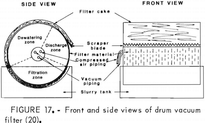
Vacuum drums can handle throughputs up to 250 gal/min, particles as small as 0.0020 in, and solids loadings between 8 and 10 pct. The average yield is between 2 and 10 lb of dry solids per square foot per hour.
Drum vacuum filters have been widely used in industry because of their adaptability with respect to filter media and cake discharge methods. A variety of filter media can be easily used with a drum filter because the material itself is attached around the circumference of the cylinder. This configuration simplifies installation, inspection, maintenance, and removal of the filter medium.
Cake Discharge Methods
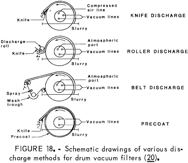
In addition to the variety of filter media available, there are many methods of removing the cake from the filter surface of a drum vacuum filter. The scraper-blade method of discharge is commonly used where the cake is friable and has poor mechanical qualities. A cake that is fairly thick and is not strongly held to the filter cloth could be easily dislodged by a blade. This blade could be steel, rubber coated, or made of other materials compatible with the particular corrosive or abrasive qualities of the filtrate or the solids. In many cases, a pressure reversal or blow is sufficient to loosen the cake from the filter medium, and the blade itself only guides the loose cake to the discharge chute.
When a precoat method is used, an advancing-knife mechanism must be precisely positioned to dislodge the cake and a minimum amount of the precoat material from the drum surface. This is an exacting procedure because the knife-advance system must not move more than several thousandths of an inch. The knife system has to be constructed so that its linear integrity, with respect to the drum face, is absolute and any deviations from the correct distance must be extremely small.
A roller discharge device may be used where a thin cake of sticky or thixotropic material is formed on the drum. This system uses a roller positioned close to the drum filter at the point of cake discharge. The cake is transferred from the filter to the roller and then removed from the roller by a cutting blade.
The belt discharge arrangement uses a filter cloth that winds around the drum to form the cake but leaves the drum to carry the solids to the discharged area. The cloth or belt passes over a small-diameter roller which causes the cake to separate from the filter. This system can be used for a cake having mechanical strength, for a thin cake, or where intensive washing of the filter is necessary to maintain the cloth openings. After the belt has passed over the discharge roll, it returns to the drum through a belt-washing system. Some of the various discharge methods are illustrated in figure 18.
Equipment Modifications
Drum vacuum filters have been modified to separate solids and liquids under adverse conditions. For example, these machines can be fitted with simple hoods which limit the escape of poisonous or foul-smelling vapors. They can be adapted for complete sealing and for operation in a nitrogen environment; however, this complicates access to the internal parts,
and the drum design must be such that the vacuum system and the cake receiving system are isolated to prevent vapor loss.
The drum vacuum filter can also be modified with accessories that improve the quality of the cake with respect to its washing and drying characteristics. This is possible because the cake moves through the washing and drying zones in the form of a continuous sheet and because the cake and filter medium are adequately supported on the drum shell. The filters can be fitted with simple rollers which extend the full width of the filter drum and can be arranged to eliminate irregularities or cracks in the cake prior to washing and drying. The wash waters and air are therefore applied to a uniform surface and will not short circuit or channel the deposited solids. The cake compression system may also have a “wash blanket” draped over the cake, which further limits any tendency for the air or wash water to channel the solids. These blankets allow the wash water to be used near the point where the cake emerges from the slurry.
Drum vacuum filters can also be designed so that the trough and hood are thermally insulated. If needed, the unit can be equipped with heat exchange equipment for heating or cooling the cake.
The basic design of the drum vacuum filter has undergone little change; however, with the development of new and improved construction materials, many options have become available. Drums can now be fabricated in a variety of metals, plastics, and rubber for handling corrosive materials. Internal piping and valves have also been improved by the use of corrosion- and abrasion- resistant materials, which greatly reduce shutdowns for repair of leaks or loss of vacuum. Tanks and agitators can also be fabricated of special materials, and tank linings have greatly reduced wear.
Performance
For any given feed condition, the performance of drum vacuum filters can be optimized by the drum speed, the vacuum, and the percentage of drum surface submerged in the feed slurry. Most drum filters have controls for the manual adjustment of these variables, and some models have automatic adjustments which are actuated by changes in the quality and quantity of the feed or cake.
A drum filter should be operated with the greatest degree of submergence and at the highest drum speed in order to maximize the throughput of solids. It should be remembered that any increase in the submergence reduces the proportion of the drum area available for washing and drying. Drum submergence above 40 pct necessitates the use of seals on the drum shaft where it passes through the trough. No matter what combinations of drum speed, vacuum, and submergence are used, the sum effect must produce a cake that can be completely and easily removed from the drum. If this cannot be achieved, the filter medium will quickly deteriorate and its life will be severely shortened.
Advantages and Disadvantages of Drum Vacuum Filters
The advantages of the rotary drum vacuum filter are—
- Continuous operation, which results in low operating labor costs.
- Many design and operational variations available for a wide range of suspensions of divergent nature.
- Clean operation.
- Low maintenance costs.
- Effective washing and dewatering.
- Provides a filtrate with a low suspended solids concentration.
- Does not require skilled personnel.
- Has low maintenance requirements for continuously operating equipment.
The disadvantages of the rotary drum vacuum filter are—
- High capital cost.
- Limitations imposed by vapor pressure of hot or volatile liquids.
- Incapable of handling products that form explosive or inflammable gases under vacuum.
- Unsuitable for quick-settling slurries.
- Tendency for cloth blinding due to thin cakes and short cycles, although this may be alleviated by the application of a belt or string discharge.
- Auxiliary equipment such as vacuum pumps is very loud.
- Consumes the largest amount of energy per unit of slurry dewatered, in most applications.
- Produces wetter cakes if blowback is used, and greater filter medium wear if blowback is used in conjunction with a scraper knife.
Rotary Disk Vacuum Filters
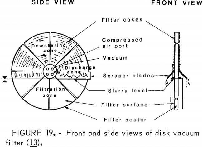
The principle of operation for the rotary disk vacuum filter is the same as that for the rotary drum filter. The disks are oriented in a vertical plane and are composed of several pie-shaped sectors which fit into a central pipe for support of the disks and for transport of the filtrate. These sectors can be removed without disturbing the others in the same disk, and at slow speeds, it is possible to change a sector while the filter is still in operation. The filter medium cloth can be slipped over each sector and fastened at the innermost end of each sector. As the disks rotate, they go through pickup and dewatering operations similar to those carried out on the drum filters. At the discharge point, the cake is removed by means of wires or knives. Figure 19 shows two simplified views of a disk filter. Disk vacuum filters are available with areas from 0.5 ft to approximately 3,300 ft²; for large areas, as many as 12 disks are used in a single unit.
Owing to the vertical disk orientation, the wide variety of discharge methods used on drum filters cannot be applied to disk filters. Thus, their application is somewhat more limited than that of the drum filters, but a disk filter will occupy only one-third the floorspace of a drum filter having the same filter medium area and is less expensive.
Disk filter provide more efficient agitation than drum filter agitators. In some applications a disk filter may be more cost efficient.
Advantages and Disadvantages of Rotary Disk Vacuum Filters
The advantages of using a rotary disk vacuum filter are—
- Low capital costs per unit area.
- Large filter areas with minimum floorspace.
- Rapid medium replacement.
The disadvantage s of the rotary disk vacuum filtration system are—
- Difficulties in washing the cake.
- Difficulties in discharging very thin cakes.
- Inflexible operation.
- High rate of medium wear with a scraper discharge.
- Unsuitability for noncoherent cakes.
Horizontal Continuous Vacuum Filters
These vacuum filters use a horizontal filter surface in the form of a table, a belt, or multiple pans in a circular arrangement. The operating principle of the horizontal filter is the same as that of the rotary drum or disk filter, where the liquid in the slurry feed passes through a filter, leaving the solids deposited on top of the media. These units can be characterized as flat-bed, high-capacity filters which lend themselves to granular, fast-filtering materials and high-specific-gravity concentrates.
Rotary Table Vacuum Filters
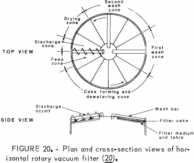
The rotary table units have a circular shape, the filter medium and supports rotate about a central axis. The feed slurry is deposited along the radius of the unit and rotates while it is being subjected to vacuum dewateriug, washing, and drying, finally being removed from the filter medium by mechanical means. Figure 20 shows a cross section of a typical horizontal table filter.
The rotary table machines permit a choice of cake thickness, washing time, and drying cycle where 4- to 5-in-thick cakes can often be handled. Sharp separations between countercurrent wash waters are also possible because of the horizontal drainage configuration. Rotary table filters, though used in industry, are better suited for dewatering free-draining solids and not sticky or thixotropic slimes because of the difficulties in removing the solids from the filter medium.
Horizontal Belt Vacuum Filters
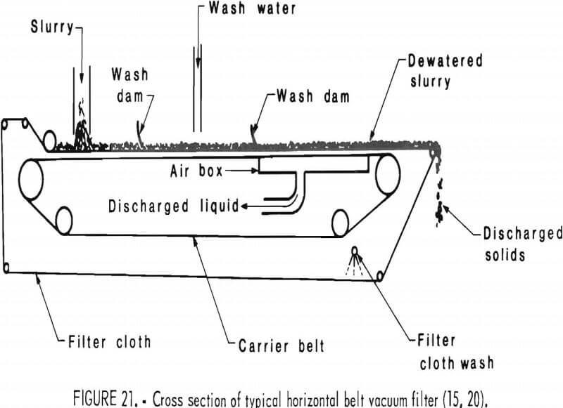
The horizontal belt vacuum filter uses an endless belt of filter fabric supported by a slotted or perforated endless belt. Both belts travel over one or more vacuum zones. The slurry is deposited onto the filter at one end, wash water is applied at one or more points along the path of belt travel, and the cake is dumped at the other end. The support belt and the filter are parted and directed along separate lines of pulleys. The filter is washed and rejoins the support belt just ahead of the slurry deposition point. Figure 21 shows a cross section of a typical horizontal belt vacuum filter.
The horizontal belt machines have a high capacity per square foot of area under vacuum, similar to the horizontal rotaries. They are well adapted for a countercurrent discharge circuit and enable the cake to be flooded with wash solvent so that it can be steeped in the wash liquid. They are suited for countercurrent leaching or washing.
Horizontal belt filters have been manufactured for more than 30 yr, but recently have they been used for large-tonnage applications that require filter cake washing. For example, the largest unit available in 1950 had only 40 ft² of active filter area, while modern machines have over 900 ft² of filter area. Many mechanical improvements have also been made on these machines, which have improved their reliability. The biggest single improvement, though, was the ability to manufacture a continuous drainage belt to very close tolerances, which spurred the development of large-capacity units.
The horizontal filter shows several advantages because the slurry deposition on the horizontal filter belt eliminates the constant slurry agitation necessary for rotary types. In the horizontal filter, the cake travels as a ribbon of unwashed cake which is gradually washed to the required purity, either concurrently or countercurrently.
Another advantage of the horizontal machine is its ability to resist filter medium blinding. Most slurries contain, in addition to some medium-sized material, a fraction of fines. No matter how efficient the agitation with the rotary drum, these fines will always be concentrated near the surface within the trough. Consequently, the fine material is sucked against the filter cloth of the rotary drum filter and causes blinding before the large particles reach the cloth. This does not happen on horizontal belt filters because the biggest particles reach the filter cloth first,
followed by the finer particles. As a result, the larger particles act as a precoat for the finer solids.
Another concern with the rotary drum and belt filters involves maintaining a vacuum. Many cakes, after being dewatered, shrink and crack. This allows air to pass freely through the cake, which reduces the vacuum and the dewatering effect on the cake. On the rotary drum filter, this is remedied by using expensive blankets, rakes, or squeeze rollers. On the belt filter, a simple sheet of impervious material such as polyethylene trailed over the cake is usually adequate to maintain the maximum vacuum.
Advantages and Disadvantages of Horizontal Vacuum Filters
The advantages of the horizontal vacuum filters are—
- Excellent wash capability.
- Flexible operation.
- High-volume operation for fast-settling solids.
The disadvantages of the horizontal vacuum filters are—
- Requirements for large floorspace.
- High initial costs.
- Unsuitability for slow settling solids.
Selecting and Sizing Filtration Equipment
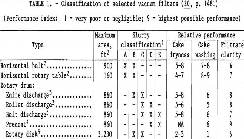
In the selection of filtration equipment, the job requirements must be compared to those associated with the equipment characteristics. Job-related factors include slurry character, production magnitude, process conditions, performance requirements, and permissible materials of construction. The equipment- related factors are the type of cycle (batch or continuous), driving force (gravity, pressure, or vacuum), production rates of largest and smallest units, separation sharpness, washing capability, dependability, feasible materials of construction, and costs. This last item must include depreciation (installed cost plus expected equipment life), maintenance, operating cost (labor, services, and filter media), and penalty of product loss (if any). In addition, consideration must be given to preconditioning and the use of filter aids. The suitability of the most common types of filters for various classes of slurries is summarized in table 1.
Continuous filters are the most desirable when the process to which they contribute is a steady-level, continuous one; however, the rate at which the cake forms and the magnitude of production rate will probably be the critical factors. For example, the use of a rotary vacuum filter is not practical if a 0.1- in-thick cake will not form under normal vacuum in less than 5 min and if more than 50 ft³/h of wet cake is to be produced. The production use of batch filters is harder to define, although they have been used in some processes that turn out 200 ton/d of dry solids. Occasionally, equipment flexibility and high filtering pressures will become more important than other factors that would otherwise dictate continuous equipment. Small-scale tests are essential for estimating the filtration rate, the washing characteristics, and other important features. Filtration is essentially an art rather than a science, and experience with the various aspects of vacuum filtration will help in better approaching the selection of equipment and evaluating test results.
Laboratory Testing
Extensive research has been done to develop laboratory procedures for determining the filterability of slurries. The filter-leaf test is the commonly used method of estimating the necessary filter area for a particular slurry. In this method, a test leaf is used which is covered with a filter medium identical to that intended for the full-scale filter. Figure 22 shows the typical apparatus
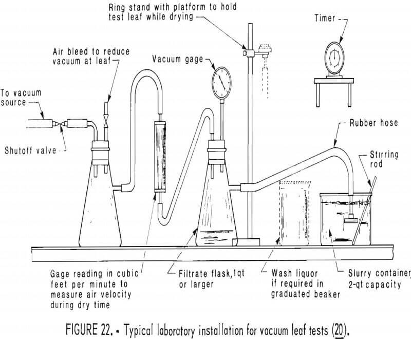
needed for a leaf test. The procedure for the test follows:
- Condition 2 qt of sludge for filtration. The sludge should be thickened to the same concentration as the production slurry.
- Apply the desired vacuum to the filter leaf and immerse in the sample for 1½ min while maintaining sample agitation. The test leaf is usually inserted upside-down in the slurry to simulate the cake formation zone of a drum filter.
- Bring the leaf to a vertical position and allow it to dry under vacuum for 3 min. This simulates the cake draining and drying part of the cycle.
- Blow off the cake for 1½ min, which gives a total drum cycle of 6 min. To discharge the cake, the leaf is disconnected from the vacuum, and air pressure of not more than 2 lb/in² is applied.
- Dry and weigh cake to determine percentage moisture, which can be computed from the equation—

where fcv = the filter cake formation rate, pounds per square foot per hour,
Wds = the dry weight of the solids cake, pounds,
tcv = the cycle time, hours,
and Atl = the filter test leaf area, square feet.
The test can be easily modified for other cycle times or discharge mechanisms. Filter leaves and testing instructions are available from most filter manufacturers. It may be necessary to adjust the results obtained by a factor to compensate for partial medium blinding and for scaling over a long period of operation. The test results will provide filtration parameters for the cake formation, drying, and washing portions of the filtration cycle. The filter-leaf test is easy to perform; however, several precautions should be observed to assure accurate results:
- Representative slurry samples should be used.
- The test should be repeated 5 to 10 times to observe any filter medium blinding.
- The sample must be continually agitated to assure that it is homogeneous.
- The vacuum must be regulated so that it does not vary during the test. The vacuum should be the same as that intended for use in the full-scale operation.
After the tests have been completed, the results can be analyzed. A graph of the moisture content of the filter-leaf test cakes versus a correlating factor should be constructed. The correlating factor is calculated from—

where Fv = the filter cake correlating factor, dimensionless,
Vav = the volume of airflow through the cake per unit area of filtering surface, cubic feet per minute per square foot,
tdv = the drying time, minutes,
Pdc = the pressure differential, pounds per square inch, gage,
and Wdst = the weight of the dry cake solids for a given cake thickness, pounds per square foot.
A decreasing moisture correlation indicates that the moisture content decreases; and as the air rate through the cake per unit of filtering area is increased, the vacuum differential, or the length of the drying time, is increased. On the other hand, if the cake thickness and the cake weight are increased, the moisture content increases. Knowing the percentage of available drying time of the filter cycle and using the design formation, such as the proper cake thickness for a given type of filter, the vacuum level, and the airflow rate through the cake, it is possible to predict for each cycle time the discharged filter cake moisture content expected from the full-scale filter. The filter area provided in the design should be for the maximum solids removal rate plus a 5- to 15-pct safety factor.
Factors Affecting Filtration
Efficient vacuum filtration is influenced by many variables, of which some can be controlled and others cannot. The following items represent many of the factors that affect the final moisture content of a filter product:
- Cake thickness.
- Pressure drop across cake.
- Drying time.
- Volume of air or gas per minute per square foot of filtering area.
- Viscosity of filtrate.
- Surface tension of filtrate.
- Filter medium.
- Size distribution of solids.
- Permeability of cake.
- Specific gravity of dry solids
- Inherent moisture of dry solids.
- Surface properties and other characteristics of solids.
- Type of filter and construction.
- Homogeneity of cake formation.
- Temperature of solids and gas.
Two other conditions—feed solids concentration and cycle time—are important in vacuum filtration because they influence many of the above factors.
The feed solids concentration is very important in the filtration process; consequently, a thickening device often precedes the filter to ensure that the feed solids concentration is consistent with economic and efficient operation. A general plot of dry cake output versus feed solids concentration reveals a curve, as shown in figure 23.
Each slurry has its own characteristic filtration curve, which must be experimentally determined. In this example, the slurry exhibits a sharp incremental rate increase above 35 pct solids. Controlling the solids concentration between the limits of 45 and 55 pct solids
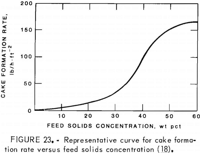
will require less filtration area and the resulting filter operating costs will be reduced. Above 58 pct solids, this slurry becomes relatively viscous and transportation to the filter will be difficult. There is a point of inflection at about 55 pct solids where the curve becomes asymptotic. This indicates that further slurry thickening above 55 pct solids is impractical and uneconomical because it produces only a slight increase in the filtration rate.
The other important consideration for filtration operations is the cycle time. In this discussion, cycle time will be concerned with rotary vacuum filters, although the same principles apply to other types of filters.
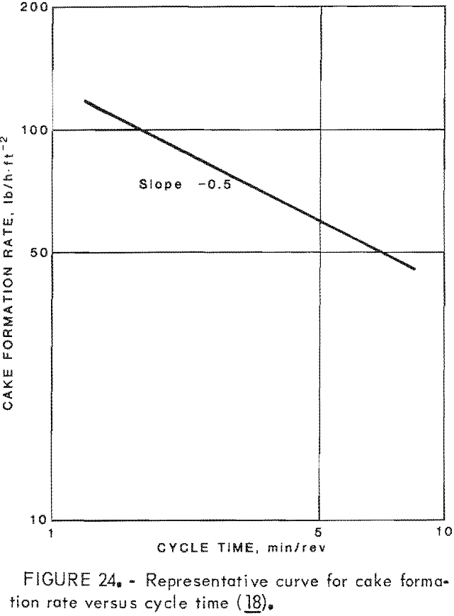
The cycle time of a continuous vacuum filter is the amount of time the filter takes to make one complete revolution and is given in terms of minutes per revolution. During each cycle, there are three phases of filter operations cake formations cake dewatering, and cake discharge. At the end of each cycle, the filter discharges a certain amount of cake per given filter area. With these data, the dry cake formation rate can be expressed in pounds per hour per square foot of filtering area. A log-log plot of dry cake formation rate versus cycle time for an arbitrary feed solids concentration is shown in figure 24.
For this example, the slope of the curve is -0.5, based on an assumption that solids concentration and cake compressibility remain constant. This relationship can be mathematically expressed as

where fcvo = the old cake formation rate, pounds per square foot per minute,
fcvn = the new cake formation rate, pounds per square foot per minute,
tcvo = the old cycle time, minutes
and tcvn = the new cycle time, minutes.
Vacuum filters are normally equipped with variable-speed drives operating within a range of 1.5 to 9.0 min/rev. Thus for any filter area, cake output can be doubled, tripled, or halved, as the situation requires.
Cycle time also affects the filter cake moisture content and dischargeability. As a general rule, the filters should be sized for a cycle time of at least 3 min/ rev and preferably 4 min/rev. Cycle times less than 3 min/rev will increase the cake moisture and produce thin cakes, which are difficult to remove from the filter medium. Difficult cake discharge can mean sizable increases in filter maintenance costs.
Hydrocyclones
Background
Cyclones have found wide use in industry for solids classification and concentration. The cyclones designed for liquids are called hydrocyclones, hydraulic cyclones, or hydroclones. The basic separation principle used in cyclones is centrifugal sedimentation, where the suspended particles are subjected to a centrifugal force which causes them to separate from the fluid. Cyclones have no moving parts, and the necessary vortex motion is provided by the fluid itself.
Hydrocyclones, by themselves, are not capable of producing a dry solids product because they use liquids for their operation. Cyclones are useful, however, in concentrating the solids content of a slurry ahead of another dewatering machine such as a filter or centrifuge.
The cyclone consists of a short cylindrical section attached to an inverted, truncated, conical section. The apex or bottom of the conical section is called the underflow orifice. A central overflow orifice or vortex finder is fitted to the base of the cone, and a feed orifice is attached tangentially to the cylindrical body section. Figure 25 shows the cross section of a typical hydrocyclone. The slurry enters at high
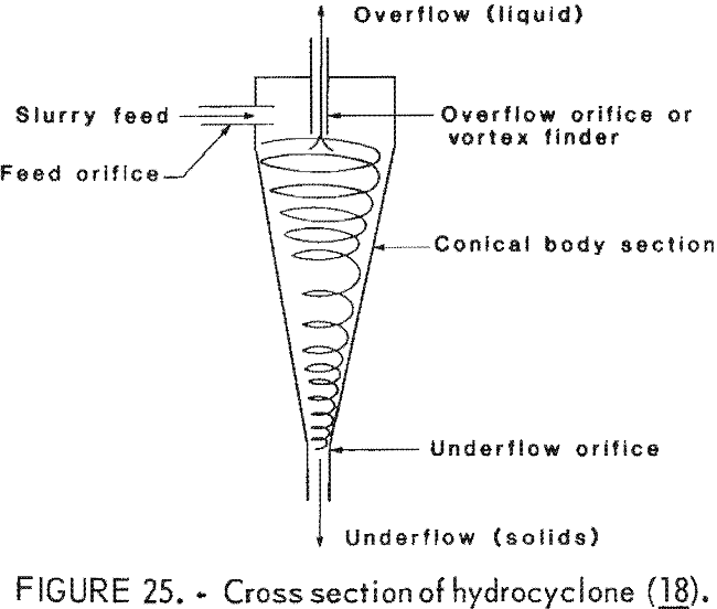
pressure through the tangential feed orifice into the cylindrical section, where a rotating force field is established. The solids in the slurry are settled to the side wall by this force, slide down the inclined wall to the apex of the cone, and exit through the underflow orifice. The liquid portion of the feed travels to the center of the cone with some of the finest solids and exits through the overflow orifice. A vortex of air extends throughout the length of the cyclone.
A cyclone is a simply constructed device; however, its principles of operation are complex and there are many variables that must be carefully evaluated to produce the desired separations. The most significant variables are—
- Cyclone diameter.
- Cyclone cone angle.
- Feed, overflow, and underflow orifice sizes.
- Length of cylindrical section.
- Feed pressure.
- Feed concentration.
- Particle size.
The hydrocyclone diameter is the most important factor influencing the application and efficiency of a cyclone because the smaller the particle to be dewatered, the smaller the cyclone diameter that must be used. For most applications, the cyclone manufacturer will determine the size and cone angle of the cyclone to be used.
The orifice size is another important factor that influences cyclone performance. The underflow orifice will determine the concentration and flow of the thickened solids from the cyclone. Enlarging the underflow orifice increases the flow rate and the percentage of fines in the underflow. The larger underflow orifice also allows more liquid to pass through it and decreases the concentration of the product. A larger over-flow orifice increases the total flow, the concentration of solids, and the maximum particle size contained in the overflow of the cone. A secondary effect is that the underflow of the cone increases in solids concentration and contains a larger percentage of coarse sizes.
Changes to the feed orifice affect the volume processed by the cone because as the area of the feed orifice is increased, there is an accompanying proportional increase in the flow to the cyclone. The additional flow reduces the retention time of the slurry within the cone and causes the cyclone to reject coarser materials to the overflow. As a result, when a cyclone feed is increased, the cyclone underflow orifice should also be increased to accommodate the higher tonnage of material fed to the cyclone.
The feed inlet can be either rectangular or circular; however, a rectangular inlet with its long side parallel with the axis of the cyclone produces better results. The top of the feed orifice should be flush with the top of the cyclone to eliminate a dead space which would cause short circuiting of the feed.
In the mineral industry it is common practice to have several vortex finders with different diameters or nozzles which can be put into the exit pipe. This enables the operator to change the length of the vortex finder, when needed. An increase in the length of the vortex finder improves the efficiency of removal of the coarse particles but decreases the efficiency for the finer particles.
The feed pressure affects the volume processed and the relative efficiency of the cyclone. The total flow to a cyclone will vary proportionally to the square root of the pressure. Increasing the feed pressure causes the underflow concentration to increase and become finer in size, while the overflow discharge increases and the overflow solids also become finer.
The interior surface of the cyclone should be as smooth as possible to promote good material flow. Abrasion resistance should be built into a cyclone if it is to be operated with abrasive solids. A wide range of construction materials, such as steel, nylon, ceramics polyurethane, and rubber, are available.
Advantages and Disadvantages of Hydrocyclones
Hydrocyclones have been used for many solid-liquid separation applications be-cause of the following advantages:
- High capacity.
- Simple operation.
- Compact design, which uses a minimum of floorspace.
- Relatively low capital costs.
- Low maintenance and processing costs.
Hydrocyclones do have a drawback, however, because the smallest particles in the slurry will be carried away with the overflow. Proper cyclone design can minimize this loss, but clarification of this liquid may be necessary, and this possibility should be recognized by the mill operator.
Sizing Hydrocyclones
The designer of a hydrocyclone installation will be concerned with the size and number of cyclones needed. This will be based on the desired separation efficiency and flow rate. Several small-diameter cyclones working in parallel are more efficient than one large cyclone handling the same capacity.
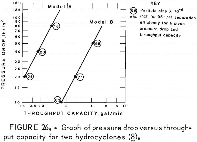
A simple, straightforward method of sizing hydrocyclones is to first determine the requirements of the installation in terms of particle size, amount of throughput, or pressure differential between the inlet and overflow orifices. Knowing this information, manufacturers’ bulletins can be consulted. Operational data for hydrocyclones are often presented in graphic form; figure 26 shows a plot of pressure drop versus throughput capacity for two representative hydrocyclones. As can be seen, these two cyclones are designed to handle very small solids.
More sophisticated methods can be used to determine the diameter, cone angle, and other dimensions for a particular situation. Their application, however,
is very complex and a reference such as Svarovsky should be consulted for a complete theoretical discussion.
Thermal Dewatering
Background
The use of heat is another method of separating liquids from solids. Thermal processes can be used to dry a slurry or just the thickened solids; however, fuel consumption will increase proportionally with the increase in the moisture present. It is, therefore, cost effective to use thermal drying after a substantial amount of moisture has already been removed by other methods such as centrifugation or filtration.
There are basically three methods of heat transfer for drying:
- Convection—the direct contact of particles with warm air.
- Conduction—the direct contact of particles with a heated shell of a dryer or other heated particles.
- Radiation—heat radiating from a hot surface to the particles.
Thermal Dryer Operation
Dryers used commercially for drying minerals commonly utilize heat transfer by convection or direct contact between the wet solids and hot air. Over the years, many different configurations of convection dryers have been available for the minerals industry. Now, six basic types exist, as follows:
- Drum.
- Suspension or flash.
- Multilouvre.
- Vertical tray.
- Continuous carrier.
- Fluidized bed.
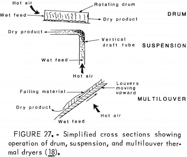
In each of these dryers, the wet solids are separated from each other and subjected to a flow of hot gases or air. In the drum-type dryer, the solids enter one end of a rotating cylinder through which the hot air is blowing. The solids are tumbled the length of the cylinder and exit the other end.
In the suspension or flash dryer, the wet solids are carried upward through a vertical duct by a blast of superheated air for a very brief time. The air is usually heated to 1,200° F, but the solids are in contact with the hot air for only a fraction of a second and are not changed chemically.
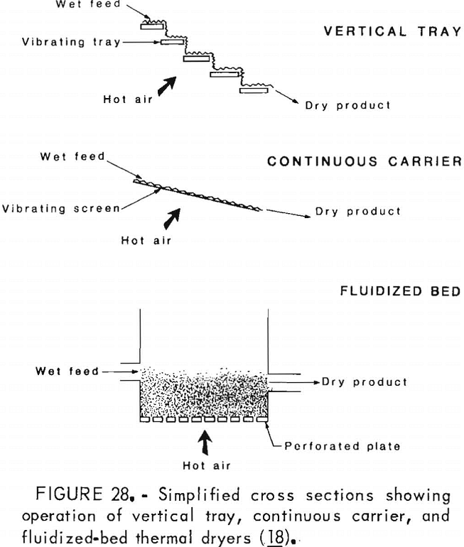
The louvered arrangement has a series of specially designed flights which carry the solids upward through a flow of hot air. The vertical tray, on the other hand, has a series of shelves placed in a terrace arrangement. The solids are fed in at the top, and a vibrating action causes them to fall from one shelf to the next through heated air. The continuous carrier type uses a vibrating inclined screen to support the solids as they tumble through the hot airstream.
The fluidized-bed dryer uses a slightly different approach and has seen wider use in the past two decades. In this type of dryer, the solids are fed into a heater box and subjected to a high-velocity flow of hot air. The violent bubbling action of the solids is similar to that of boiling water, leading to the description of the dryer as a fluidized bed. Figures 27 and 28 show simplified cross sections of the various thermal dryers.
Advantages and Disadvantages of Thermal Dryers
Thermal dewatering equipment has several advantages, which include—
- Ability to reduce the moisture content of slimes to 6 pct or less.
- Minimal labor requirements.
- Capability to operate continuously as long as feed material is available.
- Low maintenance costs.
There are, however, several disadvantages, such as—
1. The moisture content of the product must be carefully monitored. If it is
too low, the powdery product may be difficult to handle or transport.
2. The fuel demands can become very high.
3. A mechanical dewatering device is usually needed ahead of a thermal dryer.
Sizing Thermal Dryers
As wet solids are dried, they go through three stages with respect to moisture loss:
- Warming period.
- Constant-rate period.
- Falling-rate period.
The constant-rate and falling-rate periods have the greatest impact on the drying time required for a particular material. The warming period will be significant if radiant heat from surrounding surfaces is negligible. The rate of liquid evaporation during the constant rate period can be estimated using mass transfer or heat transfer equations as follows:
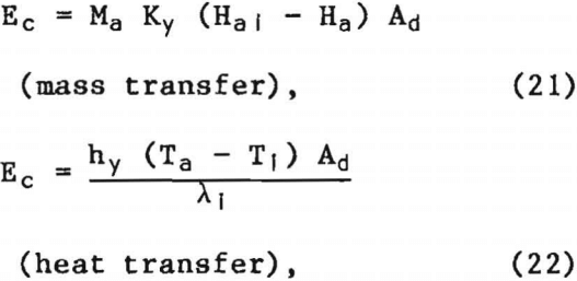
where Ec = the rate of evaporation, pounds per hour,
Ma = the molecular weight of air, pounds per pound-mole.
Ky = a mass transfer coefficient, pound-moles per square foot per hour,
Ha = the humidity of the ambient air, pounds of water per pound of dry air,
Hal = the humidity of the air at the solid-air interface, pounds of water per pound of dry air,
Ad = the drying area, square feet,
and hy = a heat transfer coefficient, Btu per square foot per hour per °F.
For airflow parallel with surface of solid, hy = (0.0128 Vam)0.8.
For airflow perpendicular to surface of solid, hy = (0.37 Vam)0.37.
Vam = the air mass velocity, pounds per square foot per hour,
Ta = the temperature of the ambient air, °F,
Tl = the temperature of the air at the solid-air interface, °F,
and λl = the latent heat of water at the temperature, Tl, of the solid-air interface, Btu per pound.
Equations 21 and 22 are valid while the surface of each particle is saturated. When this condition is no longer the case, thermal drying enters the falling rate period.
If the total average moisture content (Xtav) of any particle is composed of the average free moisture (Xfav) and chemically bound or equilibrium moisture (Xeq), the rate of liquid evaporation can then be estimated by the liquid diffusion equation, which is—
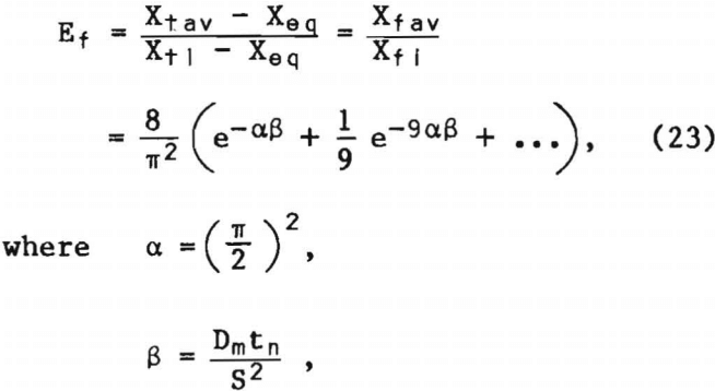
Ef = the rate of liquid evaporation during the falling rate period, pounds of water per pound of dry solid,
Xtl = the initial total moisture content of the solids, pounds of water per pound of dry solid,
Xtav = the average total moisture content during the falling rate period, pounds of water per pound of dry solid,
Xeq = the equilibrium moisture content of the solids, pounds of water per pound of dry solid,
Xfl = the initial free moisture content at the beginning of the falling rate period, pounds of water per pound of dry solid.
Xfav = the average free moisture content during the falling rate period, pounds of water per pound of dry solid,
e = Euler’s number – 2.71828,
Dm = the diffusivity value of moisture through a solid, square feet per hour,
tn = any arbitrary time after the beginning of the falling rate period, hours,
and S = one-half the thickness of the layer of solids in the dryer, feet
These equations are helpful in estimating the rate of evaporation of moisture and will enable the designer to determine the total drying time, feed rate, air-volume requirements, and other important factors concerning thermal dryers.
When a fluidized-bed dryer is being considered, the pressure drop across the orifice plate must be evaluated and the plate size designed accordingly. For most applications, a pressure drop equal to 10 or 12 in of water is adequate. Pressure differences slightly higher than this should be used if the fluidizing gases are as hot as 1,200° F.
The pressure drop will increase as the percent open area in the plate is decreased. To design for the percent open area, a factor called the discharge coefficient must be determined with the aid of a single-orifice test plate that has the same cross-sectional characteristics as the proposed full-scale dryer. Information obtained from the test plate can be used in the following equation to determine this coefficient:

where Cd = the discharge coefficient, dimensionless
qa = the airflow through the orifice plate for the air temperature and pressure used during the test, cubic feet per minute,
Ma = the molecular weight of air, 29,
Pop = the mean absolute pressure in the orifice, pounds per square inch,
Ao = orifice area, square feet,
Pdo = the pressure differential across the orifice, inches of water,
and Tk = the temperature, kelvins
After the discharge coefficient has been determined for a particular orifice configuration, the volume of air needed to pass through the orifice to provide the necessary pressure drop can be calculated. The total number of orifices for the full-scale dryer can then be found if the designer knows the volume of air needed to maintain the pressure drop for one orifice and the total volume of air needed for drying the solids.
These equations will provide approximate values for sizing thermal dryers, but as with other equipment, it is recommended that pilot-plant testing be done.
Current Bureau of Mines Research on Desliming Methods
The bulk of this review has been concerned with well established methods of dewatering slimes; however, at least two Bureau of Mines innovations for dewatering slimes should also be brought to the attention of the mining industry: Electrokinetic methods and the rotary trommel.
Electrokinetic Methods
Background
The Bureau is currently developing a method of dewatering slimes using an electrokinetic potential. This dewatering technique is intended to be used at the place of the slimes disposal rather than in the mill or other processing location. This method takes advantage of the electrical surface charge on the solid particles in a water suspension. Bureau of Mines research has shown this technique to be generally successful for treating siliceous mine tailings from several north Idaho metal mines, thickener underflow from two Appalachian coal preparation plants, and materials from numerous other coal and metal mine sites.
Not all slimes or sludges can be dewatered by this method, however, because the sludge from an acid mine drainage treatment plant and scrubber sludge from a large coal-fired powerplant were not responsive to this technique. The physical properties of the slurries that affect their response to treatment include electrical conductivity, particle-size distribution, water content, and surface charge density. Chemical properties also influence behavior, but their importance is specific to each sample and difficult to characterize.
Application
The electrokinetic phenomena of electrophoresis and electroosmosis are principally responsible for the effects observed. Electrophoresis is the migration of small electrically charged particles through a stationary liquid due to an external electrical potential. Electroosmosis, on the other hand, is the migration of liquid through a stationary porous solid as a result of an external electrical potential.
Particle sedimentation can be accelerated by imposing a properly oriented electrical field on a slurry. For example, in a slurry composed of negatively charged solids, the anode or positive electrode is located at the bottom of the slurry, and the cathode or negative electrode is positioned at the surface (fig. 29).
Practically speaking, the anode can be a section of abandoned steel track or wire mesh placed on the floor of the fill area prior to the slurry deposition. The cathode can be wire mesh positioned at the slurry surface and suspended from wood floats or cables attached to the roof of the mine opening. A relatively large direct voltage of 2 to 6 V/in² of tailings surface area is applied to the electrodes, and the negatively charged solids begin migrating downward to the positively charged anode. The electrophoretic migration will effectively accelerate the settling of these solids.
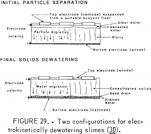
When sedimentation is complete, further drainage can be stimulated by reversing the polarity so that the bottom electrode becomes the negatively charged cathode. The water immediately adjacent to the negatively charged solid particles will contain excess dissolved positive ions that, in effect, give this water a positive charge. In an electrical field established between two separated electrodes buried in a slurry, the solid particles will not move appreciably because of their relatively dense packing, but the water will be carried toward the negatively charged cathode by the viscous drag of the migrating positive ions. This movement of water by direct current potential is electroosmosis. As the water migrates to the cathode, the liquid can be removed by using slotted pipes or gravel drains.
Electrophoretic flow is relatively independent of pore size and is particularly attractive for dewatering dense slurries of fine particles where hydraulic flow of water through the sediment is negligible because of small pore size. Feasibility of electrokinetic dewatering for a particular slurry is best determined by direct testing in the laboratory. The complex interaction of factors affecting the efficiency of the process has prevented the use of physical properties alone as reliable predictors of performance. Change in application methods, such as current density, current reversal, electrode configuration, or settlement time, can also have unique and important effects on the response of a given slurry.
Current Research and Use
Field tests conducted in two Idaho mines demonstrated that the electrokinetic process can effectively dewater and density unclassified mill tailings or slimes for use as backfill, with moderate power consumption. One mine is preparing to use the process to dewater slimes underground as a regular operating procedure, and another mine plans to use it when space occupied by old slime deposits needs to be recovered for other purposes.
Trommel Screen
Description of the Method and Equipment
The Bureau is also doing extensive research on the trommel screen for dewatering slurries. In this method, the slurry is first mixed with a flocculating agent to agglomerate the small particles into much larger masses. Next, the treated slurry passes over a hydrosieve to remove some of the liquid. The remaining wet solids then go into the upper end of a long inclined cylinder or trommel made of steel screen. The trommel rotates about its long axis and allows any remaining liquid to pass through the screen while the dewatered solids move through the cylinder and exit through the lower end (fig- 30).
The most important aspect of this method is adding the proper flocculant to the slurry. It must cause the solids to form sufficiently large masses that will not pass through the screen with the liquid but will remain on top of the screen surface. At the same time, the flocculating agent must be potent enough so that a minimum amount of the chemical will produce the required flocculation. Extensive testing has indicated that polyethylene oxide (PEO) is suitable for use with many different slurry types in the trommel screen. This flocculating agent is a water-soluble polymer having a nominal molecular weight of 8 million. This agent causes slurry solids to flocculate within minutes and works well with the hydrosieve and trommel screen
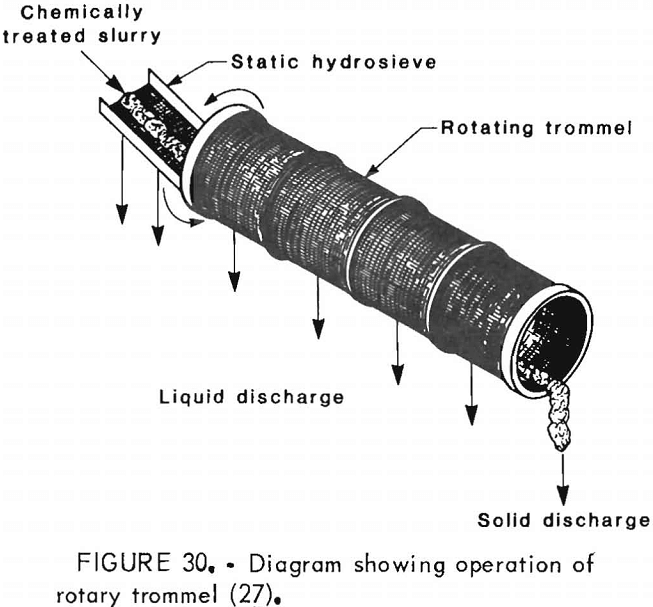
The hydrosieve used for this research was constructed of stainless steel and was 8 ft long. The first 4 ft had screen openings of 0.04 in, and the last 4 ft had openings of 0.02 in. The hydrosieve was inclined at an angle of 58° from horizontal.
The trommel screen was also composed of stainless steel but had 10-mesh openings. The trommel had a length of 36 in and a diameter of 6 in. The angle of inclination from horizontal was between 3° and 9°. The slurry moved over the hydrosieve and through the trommel by gravity.
Test Results
Test results using this method indicate that phosphatic and coal-clay slurries can be successfully dewatered. In one particular test, a coal-clay slurry had 23.9 wt pct solids, of which over 70 pct were smaller than 325 mesh. A solution containing 0.125 wt pct PEO was added to the slurry at a dose of 0.78 lb PEO per ton of dry solids. The dewatered product had 60.1 wt pct solids. This impressive value is representative of the results obtained so far.
Conclusions
Research on the trommel screen is on-going, so no information is available on production costs per ton of dried solids. The equipment is fairly simple in design and would not represent a substantial capital investment; however, this method does require chemical pretreatment that would significantly affect the cost of dewatering slimes. Nonetheless, this method shows promise for mineral industry use, and research is continuing on the refinement of the trommel screen.
Discussion
In recent years, economic pressures have caused milling operations to maximize the separation of economic minerals from the waste material. This has been done by grinding the ore to much smaller particle sizes. This fine grinding, while increasing the mineral extraction, has also posed a serious disposal problem for the waste material. As practically all mineral beneficiation involves the use of water, the resulting solid-liquid mixture or slurry must be properly disposed of in accordance with the current environmental regulations.
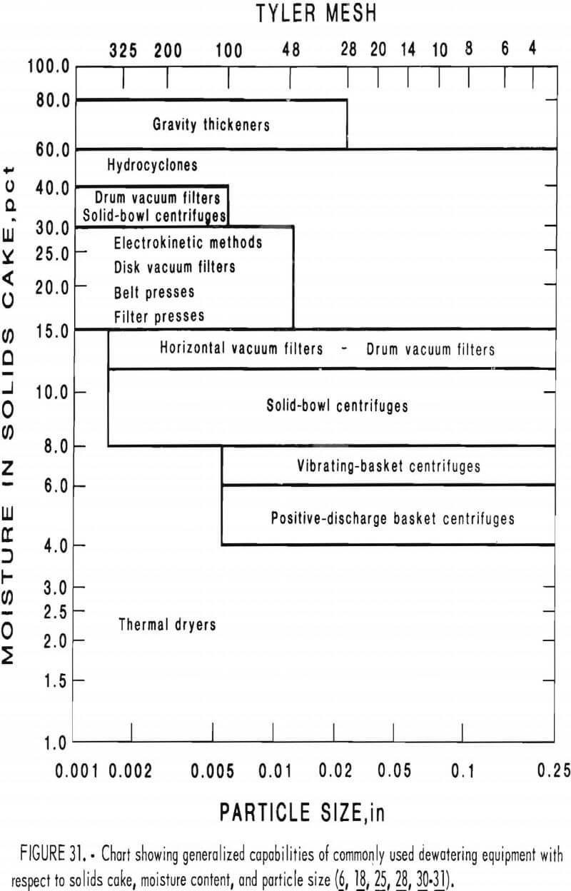
There is an abundance of dewatering equipment available that can separate the solids from the water with varying degrees of efficiency. Physical separation methods, such as gravity thickeners, centrifuges, filters, thermal dryers, and cyclones, all reduce the water content or increase the solids content of the slurry. Although these items were discussed separately, they can be used in conjunction with each other to produce a solids mass with an acceptably low moisture content. Figure 31 shows the relative capabilities of common pieces of dewatering equipment in terms of the slurry particle size.
The Bureau is continuously doing research that will benefit the mining industry. Classical dewatering methods are being improved, and new methods are being devised. Electrokinetics and the rotary trommel are but two ongoing Bureau projects that should help the mining industry reduce costs and increase efficiency.
Despite the amount of knowledge we have concerning dewatering, its practice is still an art. Each mine generates waste material which, in one way or another, is different from the waste of any other mine. Variations in mineral content and physical properties must be evaluated carefully so that the right combination of equipment and methods will produce a sufficiently dry product. This paper was prepared in order to give the mill operator or owner an overview of what dewatering equipment is available. An awareness of the different dewatering practices will enable such operators to evaluate alternatives that perhaps would not have been considered otherwise. This paper should also serve as a basis for further detailed research into the many ways of meeting the desliming challenge.
Equipment Efficiency
Less than perfect performance of separation equipment can be characterized by the separation efficiency. The grade efficiency concept can be applied to solid-liquid separation equipment whose performance does not change with time if all operational variables are kept constant. Hydrocyclones, centrifuges, and gravitational thickeners are examples of such equipment. This concept is not widely used in filtration because the efficiency changes with the amount of solids collected on the face of the filter medium. For filtration, though, it is helpful to determine the grade efficiency of the clean medium, which influences the initial retention characteristics of the filter and can be used for filter rating.
Total Efficiency
The total efficiency for dewatering equipment can be determined by the equation

where Et = the total equipment efficiency ,
Ms = the mass of all solids separated from a slurry liquid,
and Mt = the mass of all slurry solids prior to solid-liquid separation.
The performance of most available separational equipment is predominantly size dependent, so the total efficiency depends on the size distribution of the feed solids and is not suitable for the general criterion of efficiency. Consequently values of total efficiency stated by equipment manufacturers may not be entirely accurate concerning the separational capability of their equipment.
Additional information must be known about the particle-size distribution of the feed solids, the density of the solids, and such operational data as flow rate, temperature, type of fluid, and solids input concentration. A single value for the total efficiency cannot be used to represent the separation capability of the equipment for any materials other than those actually tested.
Grade Efficiency
The efficiency of separation equipment, however, can be characterized by a gravimetric grade efficiency function, G(x). This is a probablistic mathematical expression, based on mass efficiency, which describes the particle trajectories during the separation process. A grade efficiency function can be developed for each type of separation equipment that describes the efficiency of separation for a range of particle sizes. This information can be graphed as an S-shaped curve, such as the one shown in figure D-1. This graph is often referred to
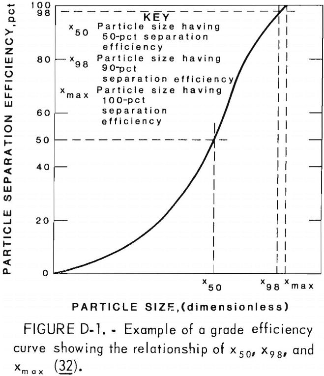
as the partition probability curve because it shows the probability for each particle size of either being separated or remaining with the fluid.
Particle Size Parameters
The grade efficiency curve can be used for determining several operational parameters for a particular piece of equipment. The particle corresponding to the 50-pct probability is called the equi-probable size, x50, and is used as the minimum cutoff size or cut size of the particular type of equipment. This cut size is independent of the feed material, and its determination requires a knowledge of the entire grade efficiency curve.
In any separation operation, there will be a particle size larger than the grade efficiency, which is 100 pct. This is the largest particle remaining in the overflow after separation of the maximum particle size that would have a chance to escape and is called xmax.
If the particle trajectories in the separator can be approximated, the most unfavorable conditions of separation are taken for determining this limit of separation. It is difficult to determine the limit of separation accurately, so the size corresponding to 98-pct efficiency, x98, is used, which gives an easily defined point. This size is called the approximate limit of separation and is widely used in filter rating. The relationship of X50, X98, and Xmax is shown in figure D-1.
The concept of grade efficiency is helpful in determining the application of a particular piece of equipment for a particular dewatering or desliming operation. For a more detailed discussion of grade efficiency, consult Svarovsky.
